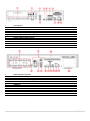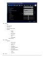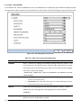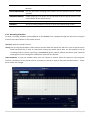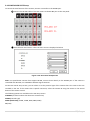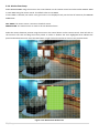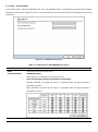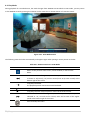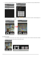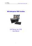
1
User’s Guide (Ver. 4.0) Analog DVR: N-0441U, N-0840U, N-1640L, N-0440MH, N-0840MH, N-1640MH, ND-1640S HD-SDI DVR: HD-0405M, HD-0810M, HD-1620S, HD-0410S, CM-1040S High Definition H.264 Digital Video Recorder [N-0441U, N-0841U] [HD-0405M, HD-0810M, N-0440MH, N-0840MH, N-1640MH, ND-0823M, ND-1643M] [HD-1620S, CM-1040S, HD-0410S, ND-1640S] About This User’s Guide Before operating the unit, please read this user’s guide thoroughly and retain it for future reference. Warning Cautions 1. Read User Guide – After unpacking this product, please read the user guide carefully, and follow all the operating and other instructions. 2. Power Sources – This product should be operated only from the type of power source indicated on the label. If not sure of the type of power supply, consult with the product dealer. 3. Ventilation – Slots and openings on the unit are for ventilation and to ensure reliable operating of the product and to protect it from overheating, and these openings must not be blocked or covered. The product is recommended to be placed in a well ventilated area. 4. Heat – The product should be placed away from heat sources such as radiators, stoves, and other products that produce heat. 5. Water and Moisture – Do not use this product near water. Do not exceed the humidity specifications for the product as detailed in the user guide. 6. Cleaning – Unplug this product from the wall outlet before cleaning. Do not use liquid cleaners or aerosol cleaners. Use only compressed air to clean the product. 7. Power Cord Protection – Power-supply cords should not be routed so that they are likely to be walked on or pinched by items placed against them. 8. Overloading – DO not overload wall outlets; extension cords, or uninterruptible power supply. 9. Lighting – For added protection for this product during a storm, or when it is left unattended and unused for long periods of time, unplug it from the wall outlet. This will prevent damage to the product due to lighting and power line surges. 10. Object and Liquid – Never insert foreign objects into the DVR, as it may touch dangerous voltage points or short-out parts that could result in a fire or electrical shock. Never spill liquid of any kind on the product. 11. Accessories – Do not place this product on an unstable cart; stand, tripod, bracket, or table. The product may fall, causing serious personal injury and serious damage to the product. 12. Disc Tray – Keep fingers well clear of the disc tray as it is closing. Neglecting to do so may cause serious personal injury and serious damage to the product. 13. Burden – No not place any heavy objects on the product. 14. Disc – Do not use a cracked, deformed, or repaired disc. These discs can be easily broken and may cause serious personal injury and cause product malfunction. 15. Replaceable Batteries – CAUTION: Risk of Explosion if the battery is replaced by an incorrect type. Dispose used batteries according to the instructions. 16. Servicing – Do not attempt to service this product. Opening or removing covers may expose the user to dangerous voltage or other hazards. Unauthorized substitutions may result in fire electric shock or other hazards. Serving should be performed only by a qualified and experienced personnel. 2|Page Notes Handling Please retain the original shipping carton and/or packing materials supplied with this product. To ensure the integrity of this product when shipping or moving, repackage the unit as it was originally received. Do not use liquids, such as aerosol spray, near this product. Do not leave rubber or plastic objects in contact with this product for long periods of time. The product may become warm after long periods of use. Locating Place the unit on a level surface. Do not place the unit on a shaky or unstable surface such as a wobbling table or an inclined stand. If the unit is placed next to a TV, radio, or VCR, the playback picture may become poor and the sound may be distorted. If this happens, place the unit away from the TV, radio, or VCR. Maintenance This DVR is designed to last for long periods of time. To keep the DVR always operational, we recommend regular inspection maintenance (Cleaning or replacement). For details, contact the nearest dealer. 3|Page Table of Contents Product Components .......................................................................................................... 7 Features .............................................................................................................................. 8 1. Name, Function and Connection ....................................................................................... 9 1-1. Front Panel ................................................................................................................................. 9 1-1-1. N-0440MH, N-0840MH, N-1640MH, HD-0405M, HD-0810M, ND-0823M, ND-1643M ............................. 9 1-1-2. ND-1640S, HD-1620S, HD-0410S, CM-1040S440MH, N-0840MH, N-1640S .......................................... 11 1-2. Rear Panel ...................................................................................................................................... 13 1-2-1. N-0441U, N-0841U, N-1640L .......................................................................................................... 13 1-2-2. N-0440MH, N-0840MH, N-1640MH, ND-0823M, ND-1643M.............................................................. 13 1-2-3. ND-1640S .................................................................................................................................... 14 1-2-4. HD-0405M, HD-0810M, HD1620S ................................................................................................... 14 1-3. Remote Control ............................................................................................................................... 16 2. Preparation .................................................................................................................. 17 2-1. DVD-RW Installation......................................................................................................................... 17 2-2. Hard Drive Installation ...................................................................................................................... 18 2-4. Storage Estimation ........................................................................................................................... 19 2-5. Booting the DVR and Basic Time Setting ............................................................................................. 19 2-6. Setting Daylight Saving Time ............................................................................................................. 20 2-7. Setting NTP (Network Time Protocol) ................................................................................................. 21 3. Setting up the DVR ........................................................................................................ 24 3-1. Setup – Main screen and Menu Tree .................................................................................................. 24 3-2. Setup – Display Mode ...................................................................................................................... 28 3-3. Setup – Record Mode ....................................................................................................................... 30 3-3-1. Recording Schedules ..................................................................................................................... 31 3-4. Setup – Device Mode ....................................................................................................................... 33 3-4-1. ALARM-OUT ................................................................................................................................. 34 3-4-2 SPOT-OUT Setup ............................................................................................................................ 34 3-4-3CONTROLLER & PTZ Setup ............................................................................................................... 35 3-4-4. Motion Zone Setup ....................................................................................................................... 36 3-5. Setup – Storage Mode ...................................................................................................................... 37 3-6. Setup – System Mode....................................................................................................................... 38 3-7. Setup – Security Mode ..................................................................................................................... 41 3-8. Setup – Network Mode .................................................................................................................... 43 3-8-1. DDNS........................................................................................................................................... 44 3-8-2. Network Ports .............................................................................................................................. 45 3-8-3. Network Stream ........................................................................................................................... 45 3-9. Setup - CONFIG Mode ...................................................................................................................... 46 3-10. Quick Setup ................................................................................................................................... 48 4|Page 4. Live, Search and Playback............................................................................................... 49 4-1. Live Viewing Screen ......................................................................................................................... 49 4-2. SEARCH Screen ................................................................................................................................ 51 4-2-1. TIME-LINE Search.......................................................................................................................... 52 4-2-2. Event Search ................................................................................................................................ 53 4-2-3. Go To First Time ........................................................................................................................... 53 4-2-4. Go To Last Time ............................................................................................................................ 53 4-2-5. Go To Specific Time ....................................................................................................................... 54 4-2-6. Archive Search .............................................................................................................................. 54 4-2-7. Log Search ................................................................................................................................... 55 4-3. Play Mode ...................................................................................................................................... 56 5. PTZ Control ................................................................................................................... 57 6. Back Up ........................................................................................................................... 58 6-1. Still Image Backup onto USB Flash Drive ............................................................................................. 58 6-2. Video Backup onto USB Flash Drive ................................................................................................... 58 6-3. Transferring Still Images or Video from the ARCHIVE List ...................................................................... 59 6-4. Playback of Backup Video ................................................................................................................. 60 7. Single Site Network Viewer................................................................................................ 61 7-1. PC Requirements ............................................................................................................................. 61 7-2. Installing the Network Viewer ........................................................................................................... 62 7-3. Live Monitoring Mode and Functions. ................................................................................................ 63 7-4. Bi-directional Audio ......................................................................................................................... 65 7-5. Remote Search Mode and Functions .................................................................................................. 65 7-6. PC System Configuration................................................................................................................... 69 8. Multi-Sites Network Viewer ............................................................................................... 72 8-1. Overview ........................................................................................................................................ 72 8-2. Minimum PC Requirements .............................................................................................................. 72 8-3. Installation of the Program ............................................................................................................... 72 8-4. Live Window ................................................................................................................................... 74 8-4-1. Main User Interface....................................................................................................................... 74 8-4-2. Control Buttons ............................................................................................................................ 74 8-5. Search and Playback Window............................................................................................................ 75 8-5-1. Main User Interface....................................................................................................................... 75 8-5-2. Main Control Panel ....................................................................................................................... 76 8-6. Operation ....................................................................................................................................... 78 8-6-1. Addition, Delete, and Modify of DVR Sites ....................................................................................... 78 8-6-2. Connect and Disconnect ................................................................................................................ 80 8-6-4. Recording Video on Local PC during Live.......................................................................................... 82 8-6-5. Local Playback and Remote Playback ............................................................................................... 84 8-6-6. AVI Backup During Playback ........................................................................................................... 86 9. Web-Browser Viewer ........................................................................................................ 88 5|Page 10. Remote Setup ................................................................................................................ 91 10-1. DISPLAY ........................................................................................................................................ 92 10-2. RECORD .................................................................................................................................... 92 10-3. DEVICE ...................................................................................................................................... 93 10-4. STORAGE .................................................................................................................................. 94 10-5. SYSTEM .................................................................................................................................... 95 10-6. NETWORK ................................................................................................................................. 97 10-7. REMOTE UPGRADE ................................................................................................................. 98 10-8. INFORMATION........................................................................................................................... 98 11. Mobile Phone Viewer .................................................................................................. 99 11-1. Installing the Viewer ...................................................................................................................... 99 11-2. iUMS for Android ........................................................................................................................... 99 11-2-1. Live ........................................................................................................................................... 99 11-2-2.PTZ Control ............................................................................................................................... 100 11-3. iUMS for iPhone .......................................................................................................................... 101 11-3-1. Live ......................................................................................................................................... 101 11-3-2.PTZ Control ............................................................................................................................... 101 11-3-3. Playback .................................................................................................................................. 102 APPENDIX: How to Connect the Network .............................................................................. 103 A. How to set the IP address of the DVR and open TCP port of the router? .............................................. 103 B. How to access DVR from a Remote PC? ........................................................................................... 106 LAN Connection – Using a Switching Hub ......................................................................................... 106 Internet Connection Using DDNS ...................................................................................................... 108 6|Page Product Components Please make sure the following components are included as specified below. DVR Set Client Software CD, User Guide Remote Control , Battery1.5V Mouse HDD Mounting Bracket & Screw* SATA Cable, SATA Power Cable HDD & DVD-RW Mounting Screw HDD & DVD-RW Mounting Bracket Power Cable & Power Adapter (1 EA) Power Cable (110V or 220V) (1 EA)* *For HD-1620S, CM-1040S, HD-0410S, ND-1640S only 7|Page Features H.264 video compression HDcctv/HD-SDI Compatible (HD-0405M / HD-0810M / HD-1620S / HD-0410S / CM-1040S Models only) HDMI 1080P Video Output (Not for N-0441U, N-0840U, N-1640L) QUADPLEX: Simultaneous live or playback while recording, network transfer, and backup USB 2.0 port for backup, firmware upgrade, configuration export/import, or USB mouse Individual channel operation such as FPS, quality, recording mode, & detection zone Various network access: Network client SW, web-viewer, smart phone APP, and CMS Remote setup and remote upgrade Remote access via PC, MAC®, or smart phones Recording by schedule, continuous, alarm, motion, or continuous Free DDNS server Bandwidth control E-mail event notification NTP (Network Time Protocol) Watermark Synchronized audio Bi-directional audio Time stamp over backup data Easy and various data backup via DVD, USB flash drive, USB external HDD, and network HDD S.M.A.R.T status check and alert via e-mail or internal beep USB mouse, IR remote control Multi OSD languages Made in Korea 8|Page 1. Name, Function and Connection 1-1. Front Panel 1-1-1. N-0440MH, N-0840MH, N-1640MH, HD-0405M, HD-0810M, ND-0823M, ND-1643M The following information will help you to operate the front panel controls. Figure 1.1.1. Front Panel Indication Lights NO. Name Description A CH1~16 Indicates that the channel is being recorded. B HDD Indicates that the system is accessing the hard disk. C ALARM Indicates that sensor(s) is/are triggered or motion is detected. D NETWORK Indicates that a network client is connected E BACKUP Indicates that a USB or DVD-RW device contains stored data F POWER Indicating that the system is powered on. Front Panel Buttons NO Name Description Channel keys. For channel 10, press the 0 key. For channel 11, 1 press the +10 and 1 key. For channel 16, press the +10 and 6 key. 2 In playback mode, press to rewind the recording. Press to select an audio mode: 3 MUTE –Mute all 4 channels. SINGLE- Highlighted channel only. MIX- Mix all 4 channels. 4 Jump/step backward. In playback mode, the playback position moves 60 seconds backward. 9|Page 5 In playback mode, press to fast forward the recording. 6 Press to enable/disable ALARM operation. Jump/step forward. In playback mode, the playback position 7 moves 60 seconds forward. 8 Press to start or stop manual recording. 9 In live display mode, press to open the SEARCH menu. 10 In playback mode, press to play/pause the footage. 11 Press to open the SETUP menu. Enable/disable the automatic sequence of display of channels 12 in full screen, quad, 9-split display mode. 13 Press to control Pan/Tilt/Zoom operations. 14 Press to capture video in jpeg format in live or playback mode. 15 (LEFT) 16 (UP) 17 (RIGHT) 18 (DOWN) 19 It is also used as the number 4 when entering password. Press to move up the menu in Setup mode. It is also used as the number 1 when entering password. Press to move right or to change the values in Setup mode. It is also used as the number 2 when entering password. Press to move down the menu in Setup mode. It is also used as the number 3 when entering password. Press to select desired menu item or to store the setup value. Press for temporary storage of the changed value or to return 20 to the previous menu screen. 21 USB Port 22 OPEN/CLOSE 23 DVD Drive 10 | P a g e Press to move left or to change the values in Setup mode. To archive still-image or video into a USB flash drive or upgrade the firmware with USB flash drive. To open and close the insert tray, press the button. To save video, insert a CD-R/DVD-R. 1-1-2. ND-1640S, HD-1620S, HD-0410S, CM-1040S440MH, N-0840MH, N-1640S The following information will help you to operate the front panel controls. Figure 1.1.2. Front panel Indication Lights NO. Name A CH1~16 B HDD C RECORD D ALARM E NETWORK F BACKUP Description Indicating that the channel is being recorded. Indicating that the system is accessing the hard disk. Indicating that the system is recording video data. Indicating that when sensor(s) is/are triggered or motion is detected. Indicating that when Network client connects through the network. Indicating that USB or DVD-RW storage device is stored images or video. Front Panel Buttons NO Name Description 1 POWER ON/ OFF 2 Channel keys. For channel 10, press the 0 key. For channel 11, press the +10 and 1 key. For channel 16, press the +10 and 6 key. 3 Press to rewind the footage in playback mode. 4 Press to select audio mode such as SINGLE, MIX and MUTE. MUTE- All of 4 channels. SINGLE- Highlighted channel only. MIX- All of 4 channels. 4 Jump/Step backward. In playback mode, the playback position moves 60 seconds backward. 11 | P a g e 5 Press to fast forward the footage in playback mode. 6 Press to enable/disable ALARM operation. 6 Jump/Step forward. In playback mode, the playback position moves 60 seconds forward. 7 Press to start or stop manual recording. 8 Press to go to SEARCH menu in live display mode. 8 Press to play/pause the footage in playback mode. 9 Enable/disable the automatic sequence of display of channels in full screen, quad, 9split display mode. 10 Press to control Pan/Tilt/Zoom operations. 11 Press to enter SETUP menu. 12 Press to capture video in jpeg format in live or playback mode. ◀(LEFT) 13 Press to move left or to change the values in Setup mode. It is also used as the number 4 when entering password. ▲(UP) 14 Press to move up the menu in Setup mode. It is also used as the number 1 when entering password. 15 ▶(RIGHT) Press to move right or to change the values in Setup mode. It is also used as the number 2 when entering password. 16 ▼(DOWN) Press to move down the menu in Setup mode. It is also used as the number 3 when entering password. 17 Press to select desired menu item or to store the setup value. 18 Press for temporary storage of the changed value or to return to the previous menu screen. 20 DVD drive To save video, insert a CD-R/DVD-R 21 USB Port To archive still-image or video into a USB memory or upgrade firmware with USB memory stick, connect a USB memory to the USB terminal on the front panel. 12 | P a g e 1-2. Rear Panel 1-2-1. N-0441U, N-0841U, N-1640L 1 2 3 4 5 6 7 8 Video Input CVBS Video Output VGA Output Audio Input Audio Output Network RS-45 Ethernet Port USB Port DC12V Power Input 1-2-2. N-0440MH, N-0840MH, N-1640MH, ND-0823M, ND-1643M 13 | P a g e Cooling Fan Video Input & Video Output Audio Input HDMI Video Output RS 232 Terminal (For testing purposes) VGA Output eSATA Port Network RS-45 Ethernet Port USB Port RS-485 PTZ Camera control terminal DC12V Power Input 1 2 3 4 5 6 7 8 9 10 11 1-2-3. ND-1640S 1 2 3 4 5 6 7 8 9 10 11 12 Video Input & Loop Out Video Output Audio Input RS-485 PTZ Camera control terminal & Sensor In terminal VGA Output HDMI Output USB Port RS 232 Terminal (For testing purposes) Network RS-45 Ethernet Port eSATA Port RS-485 Termination DC12V Power Input 1-2-4. HD-0405M, HD-0810M, HD1620S 14 | P a g e 1 2 3 4 5 6 7 8 9 10 11 Cooling Fan HD-SDI Video Input Audio Input HDMI Video Output RS 232 Terminal (For testing purposes) VGA Output eSATA Port Network RS-45 Ethernet Port USB Port RS-485 PTZ Camera control terminal DC12V Power Input 10 11 eSATA Port RS-485 DC12V Power Input 1 2 3 4 5 6 7 8 9 10 11 12 13 Video Input & Loop Out Video Output Audio Input RS 232 Terminal (For testing purposes) VGA Output HDMI Output USB Port RS-485 PTZ Camera control terminal Network RS-45 Ethernet Port eSATA Port RS-485 Termination Sensor In terminal DC12V Power Input 15 | P a g e 1-3. Remote Control ① ID: When a remote control ID number is set in the DVR, input the DVR ID number. ② REC: To start and stop manual recording. ③ Number: To select channel (1, 2, 3, & 4) or to enter DVR ID number. ④ F/REW: During playback - To move the playback position 60 seconds backward. During pause - To move the playback position 1 frame backward. ⑤ F/ADV: During playback - To move the playback position 60 seconds forward. During pause - To move the playback position moves 1 frame forward. ⑥ REW: To rewind the footage at 1x, 2x, and 4x speed during playback. ⑦ PLAY/PAUSE: To play or to pause the footage in playback mode. ⑧ FF: To fast forward the footage at 1x, 2x, and 4x speeds during playback. ⑨ Control button: Press to move the menu items or select channel. ⑩ SETUP: To launch SETUP menu. ⑪ SEARCH: To go to the search menu. ⑫ ESC: During setting - To return to previous menu screen. During playback - To exit from playback System Lock – To lock a system when pressing ESC button for 5 seconds. System Unlock – To unlock a system when pressing ESC button for 5 seconds. ⑬ BACKUP: To start operations of backup in live or playback mode. (The same function button as CAPTURE on the front panel of DVR) ⑭ SEQ: To start auto sequencing of the screen in full screen mode. (Toggle) 16 | P a g e 2. Preparation 2-1. DVD-RW Installation 1. Remove the screws and the top cover 2. Install the DVD-RW mounting bracket to the DVD-RW by using the as specified below. mounting bracket screws as specified below. 3. Connect the DVD-RW Data Power Cable to both the DVD-RW and main board. 17 | P a g e 2-2. Hard Drive Installation 1. Before installing bracket and screws onto the 2. Install the mounting bracket on the HDD. HDD. 3. Installation HDD and Bracket onto base case (Inside) 5. Connect the Data Power cable to the HDD. 18 | P a g e 4. Installation HDD and Bracket onto base case (Outside) 6. Installed HDD and DVD-RW. 2-4. Storage Estimation Analog DVR Recording Condition: 4CH * D1 * 30fps * Continuous HDD Level 5 (H) Level 4 Level 3 Level 2 Level 1 (L) Capacity day(s) day(s) day(s) day(s) day(s) 250GB 2 3 5 7 11 500GB 5 7 11 15 22 1TB 11 15 22 30 45 2TB 22 30 45 60 90 HD-SDI DVR 4-Channel, Continuous, 1280x720@30fps, Audio On HDD Level 5 (H) Level 4 Level 3 Level 2 Level 1 (L) Capacity day(s) hour(s) day(s) hour(s) day(s) hour(s) day(s) hour(s) day(s) hour(s) 250GB 0 22 1 3 1 12 1 20 2 6 320GB 1 5 1 12 2 0 2 9 3 23 500GB 1 22 2 10 3 5 3 20 4 18 1TB 4 23 5 23 6 14 7 21 9 18 1.5TB 6 0 7 12 10 22 11 21 14 18 2TB 8 1 10 1 13 7 15 22 19 18 2-5. Booting the DVR and Basic Time Setting 1. During the first start up, the following message will be displayed. 2. After the system initializing is completed, select the language and set date and time as specified below. 19 | P a g e 2-6. Setting Daylight Saving Time If the DVR is to be set Day Light Saving Time and be synchronized NTP (Network Time Protocol), Take next steps. 1. Click a mouse-right button or SETUP button on the front panel of DVR to enter the SETUP mode. The default Password is “1111”. 2. Go to SETUP>SYSTEM>SET DATE & TIME 3. Select DAYLIGHT SAVING. 20 | P a g e 2-7. Setting NTP (Network Time Protocol) 1. When the DVR is connected with internet and the DVR need to be syncronized with NTP (Network Time Protocol), set SETUP>SYSTEM>NTP ON. 2. Select proper TIME ZONE time. Pacific Time Zone Los Angles, CA, USA : GMT - 8:00 for Standard time / GMT - 7:00 for Daylight time Mountain Time Zone Denver, CO, USA : GMT - 6:00 for Standard time / GMT - 5:00 for Daylight time Central Time Zone Chicago, IL, USA : GMT - 7:00 for Standard time / GMT - 6:00 for Daylight time Eastern Time Zone Newyork, NY, USA : GMT - 5:00 for Standard time / GMT - 4:00 for Daylight time State Standard Time Daylight-Saving Time AL Alabama GMT-6 GMT-5 AK Alaska GMT-9 GMT-8 AK Alaska (Aleutian Islands) GMT-10 NA 21 | P a g e AZ Arizona GMT-7 NA AZ Arizona (Navajo) GMT-7 GMT-6 AR Arkansas GMT-6 GMT-5 CA California GMT-8 GMT-7 CO Colorado GMT-7 GMT-6 CT Connecticut GMT-5 GMT-4 DC District of Columbia GMT-5 GMT-4 DE Delaware GMT-5 GMT-4 FL Florida GMT-5 GMT-4 FL Florida (W) GMT-6 GMT-5 GA Georgia GMT-5 GMT-4 HI Hawaii GMT-10 NA ID Idaho (N) GMT-8 GMT-7 ID Idaho (S) GMT-7 GMT-6 IL Illinois GMT-6 GMT-5 IN Indiana GMT-5 GMT-4 IN Indiana (SW / NW) GMT-6 GMT-5 IA Iowa GMT-6 GMT-5 KS Kansas GMT-6 GMT-5 KS Kansas (W) GMT-7 GMT-6 KY Kentucky (E) GMT-5 GMT-4 KY Kentucky (W) GMT-6 GMT-5 LA Louisiana GMT-6 GMT-5 ME Maine GMT-5 GMT-4 MD Maryland GMT-5 GMT-4 MA Massachusetts GMT-5 GMT-4 MI Michigan GMT-5 GMT-4 MI Michigan (W) GMT-6 GMT-5 MN Minnesota GMT-6 GMT-5 MS Mississippi GMT-6 GMT-5 MO Missouri GMT-6 GMT-5 MT Montana GMT-7 GMT-6 NE Nebraska GMT-6 GMT-5 NE Nebraska (W) GMT-7 GMT-6 NV Nevada GMT-8 GMT-7 NH New Hampshire GMT-5 GMT-4 NJ New Jersey GMT-5 GMT-4 NM New Mexico GMT-7 GMT-6 NY New York GMT-5 GMT-4 NC North Carolina GMT-5 GMT-4 22 | P a g e ND North Dakota GMT-6 GMT-5 ND North Dakota (W) GMT-7 GMT-6 OH Ohio GMT-5 GMT-4 OK Oklahoma GMT-6 GMT-5 OR Oregon GMT-8 GMT-7 OR Oregon (E) GMT-7 GMT-6 PA Pennsylvania GMT-5 GMT-4 RI Rhode Island GMT-5 GMT-4 SC South Carolina GMT-5 GMT-4 SD South Dakota (E) GMT-6 GMT-5 SD South Dakota (W) GMT-7 GMT-6 TN Tennessee (E) GMT-5 GMT-4 TN Tennessee (W) GMT-6 GMT-5 TX Texas GMT-6 GMT-5 TX Texas (W) GMT-7 GMT-6 UT Utah GMT-7 GMT-6 VT Vermont GMT-5 GMT-4 VA Virginia GMT-5 GMT-4 WA Washington GMT-8 GMT-7 WV West Virginia GMT-5 GMT-4 WI Wisconsin GMT-6 GMT-5 WY Wyoming GMT-7 GMT-6 NOTE: If you want the unit to automatically synchronize the local time, the Time Zone must be properly set according to your local Time Zone. 23 | P a g e 3. Setting up the DVR The following sections detail the initial setup of the DVR. 3-1. Setup – Main screen and Menu Tree To enter the setup menu, right click on the mouse and select setup from the submenu or press the setup button on the front panel or the remote control. Figure 3.1.1. Setup Menu Tree When the DVR prompts the LOG-IN window, enter the PASSWORD using the virtual keyboard, or the front panel, or the remote control. The factory default password is 1111. It is highly recommended to assign a new password to protect the system. User can assign a new password in SECURITY setup menu. 24 | P a g e DISPLAY – OSD – OSD CONTRAST – SEQUENCE – SEQUENCE DWELL TIME – CHANNEL NAME - COVERT - BRIGHTNESS - CONTRAST - HUE - SATURATION VIDEO OUTPUT RECORD – - CHANNEL - RESOLUTION - FRAME RATE - QUALITY - RECORDING - SENSOR RECORDING - PRE RECORD - POST EVENT RECORD - AUDIO - SCHEDULE DEVICE 25 | P a g e – – – – ALARM OUT - SENSOR IN - MOTION ON - VIDEO LOSS ON - ALARM DURATION - ERROR ALARM CONTROLLER & PTZ - CHANNEL - NAME - SPEED - ID SPOT OUT - SPOT OUT 1 - SPOT OUT 2 CHANNEL - MOTION ZONE - MOTION SENSITIVITY – KEY TONE – REMOTE CONTROLLER ID – SENSOR - TYPE STORAGE – OVERWRITE – DISK FORMAT – DISK INFO – RECORDING LIMIT – S.M.A.R.T SYSTEM – DVR-ID – DESCRIPTION – LANGUAGE – DATE FORMAT – SET DATE & TIME - DAYLIGHT SAVING - SET DATE & TIME – CLIENT ACCESS – NTP – SEND EMAIL SECURITY – USER AUTHENTICATION (ADMIN, NETWORK, USER1, USER2, USER3) – USER PASSOWRD 26 | P a g e – PLAYBACK AUTHORITY NETWORK – PORT – NETWORK AUDIO PORT – WEB PORT – NETWORK TYPE (DHCP, LAN) – DDNS – NETWORK STREAM CONFIG – SAVE SETUP TO A USB – LOAD SETUP FROM A USB – LOAD DEFAULT – LOAD FACTORY DEFAULT – SOFTWARE UPGRADE QUICK SETUP – USE QUICK SETUP - – INPUT DESIRED DAYS CUSTOMER SETTINGS - RESOLUTION - FRAME RATE - QUALITY - RECORDING - DAYS TO RECORD 27 | P a g e 3-2. Setup – Display Mode In the SETUP menu, select the DISPLAY tab. Then, the DISPLAY menu is displayed as pictured below. Navigate through the menu items using the mouse or the control button (◀ ▲ ▶ ▼) on the remote control and change the value of the menu item. Figure 3.2.1. Display Mode Setup Screen Table 3.2.1. Menu Items in DISPLAY Mode Setup Item Description OSD Enable/disable on-screen-display. OSD CONTRAST Set the visibility level of the On Screen Display (OSD) (0~100) SEQUENCE Enable/disable sequential display of video in full screen mode. SEQ-DWELL Set the dwell time of each, quad or 9 channels display in sequential display mode. (3- TIME 60seconds) CHANNEL Select a channel for applying the following settings using the mouse or control button on the remote control. Press the right square button to change the setting value of all channels at once. Press SEL button to change the setting value of all channels at once. Left click on the mouse to highlight the setting and double-click if you want to change the value. Once the value has been changed, select OK to confirm the changes. (COVERT, BRIGHTNESS,CONTRAST,HUE,SATURATION) 28 | P a g e NAME Set the channel name. Press the right square button and set the channel name and select OK using the mouse or the control button (◀ ▲ ▶ ▼) on the remote control. The name can be made by 10 characters at most. COVERT Enable/disable display of the specified video channel in live display mode. BRIGHTNESS Change the brightness value of the specified channel. (0~100) CONTRAST Change the contrast value of the specified channel. (0~100) HUE Change the hue value of the specified channel. (0~100) SATURATION Change the saturation value of the specified channel. (0~100) VIDEO OUTPUT Allows user to set monitor output resolution from 720p 50Hz/60Hz, 1080i 50Hz/60Hz, 1080p (HDMI/VGA) 50Hz/60Hz 29 | P a g e 3-3. Setup – Record Mode In the SETUP menu, select the RECORD tab. Then, the RECORD menu is displayed as pictured below. Navigate through the menu items using the mouse or the control button on the remote control and change the value of the menu item. Figure 3.3.1. Recording Mode Setup Screen Table 3.3.1. Menu Items in Recording Mode Setup Menu Item CHANNEL Description Select a channel for applying the following settings using the mouse or the control button on the remote control. Press the right square button to change the setting value of all channels at once. Once you the value has been changed, select OK to confirm the changes. (RESOLUTION, FRAME RATE, QUALITY, RECORDING, PRE RECORD and POST EVENT RECORD) RESOLUTION Analog DVR: Select either CIF, Half D1 and D1 using the mouse or the control button on the remote control. HD-SDI DVR: Select either 640 x 360, 1280 x 720, 1920 x 1080 using the mouse or the control button on the remote control. QUALITY Select the recording quality for the specified channel. LEVEL 1 ~ LEVEL 5 (Allows the user to change the recording QUALITY of the selected CHANNEL) RECORDING Assign the recording mode for each channel. Options are: Continuous, By Motion, By Sensor, By Schedule or Disable. 30 | P a g e PRE RECORD Enable/disable pre-event recording. Pre-event recording time is 5 seconds to 20 Minutes. POST EVENT RECORD Set the post event recording time duration for the specified channel. (10~60 seconds) SENSOR RECORDING Enable setting up to 4 sensors for the specified channel using the mouse or the control button of the remote control. AUDIO Enable/disable audio recording for the specified channel. SCHEDULE Set the recording schedule. Press SEL to enter the schedule setup screen. 3-3-1. Recording Schedules To setup a recording schedule, select SCHEDULE in the RECORD menu. Navigate through the menu items using the mouse or the control button on the remote control. [Channel]: Select the specific channel. [Setup]: Set up using the left button of the mouse to section under the specific day and time. It can set the all section under the specific day or time at a time when pressing the specific day or time. It is also possible to set up recording modes of various type using a CONTINUOUS (green), Motion (yellow) and Sensor (red). Left-Click and drag the mouse to change the schedule for more than one timeslot. [COPY Schedule]: To copy the schedule setup from one channel to another, select the channel to copy using the mouse or the buttons on the remote control, and select to channel to copy to and press the select button. Select OK to confirm the changes. 31 | P a g e Figure 3.3.2. Schedule Recording Setup Screen 32 | P a g e 3-4. Setup – Device Mode In the SETUP menu, select the DEVICE tab. Then, the device menu is displayed as pictured below. Navigate through the menu items using the mouse or the control button on the remote control and change the value of the menu item. Figure 3.4.1. Device Mode Setup Screen Table 3.4.1. Menu Items in Device Setup Screen Item Description ALARM OUT Set the sensor, motion, and video loss for each alarm. CONTROLLER & PTZ Set the PTZ baud rate, protocol, and ID. SPOT-OUT Set the all details for spot monitoring. It supports 2 spot-outs. CHANNEL Select specified channel for motion zone setup. MOTION ZONE Select either Full Zone or Partial Zone for motion sensing. MOTION SENSITIVITY Set the motion sensitivity for the specified channel. Control the motion sensitivity from 1 to 9. KEY TONE Enable/disable key tone. REMOTE CONTROL ID Select an ID of remote control. 1. Select ID number. 2. Press the same number as ID set in DVR on the remote control. 3. An icon will be displayed on the Live Screen that corresponds to the remote control ID number.0 The options are from 0 to 99 SENSOR Select sensor NO from 1 to 4 TYPE Set the type of sensor for the specified channel. Options are: OFF, N/O (normal open), and N/C (normal closed). 33 | P a g e 3-4-1. ALARM-OUT Figure 3.4.2. ALARM-OUT Setup Screen Table 3.4.2. Menu Item in ALARM-OUT Setup Screen Item ALARM OUT Description Select an Alarm out number. Available No: 4 CH (1) SENSOR IN Enable Alarm Out by Sensor up to 4 Inputs. MOTION ON Enable Alarm Out by Camera Motion up to 4 cameras. VIDEO LOSS ON Enable Alarm Out by Video Loss up to 4 cameras. ALARM DURATION Set the alarm dwell time from 5 to 60 seconds. ERROR ALARM Set the error type for the alarm activation. The options are OFF, ALL, HDD ERROR and VIDEO LOSS. 3-4-2 SPOT-OUT Setup Figure 3.4.3. SPOT-OUT Setup Screen Table 3.4.3. Menu item in SPOT-OUT Setup Screen Item Description SPOT ON EVENT Enable/Disable display of the channel when an event is active. SPOT EVENT Set the dwell time for the display of the event activated channel. DWELL TIME (1-10sec) SEQUENCE Enable/disable sequential display of spot channel in full screen. If select ON, spot channel selection screen is displayed. SEQ-DWEL TIME Set the dwell time for the spot channel display.(1-10sec) SP’OT CHANNEL Select a channel for spot monitoring using the mouse or the control button on the remote control and press OK button. 34 | P a g e 3-4-3CONTROLLER & PTZ Setup To control the PTZ functions of the camera, connect a controller to the RS-485 port. ① Connect the RS-485 cables of the PTZ camera to the RS-485 port on the rear panel. ② Press the PTZ menu button. Then PTZ menu screen is displayed as below. Figure 3.4.4. PTZ Control Setup Screen Note: For speed dome cameras that support RS-485, connect them directly to the RS-485 port. If the camera is controlled with RS-232C, use a RS-485 to RS-232C signal converter. On the PTZ control setup screen, you can select or set the protocol type of the camera that is the same as the one installed on the site. If the camera has a specific camera ID, select the camera ID using the mouse or the control button of the remote control. The following options are available on the PTZ setup screen. CHANNEL (Channel number that the PTZ is connected to) NAME (Protocol type) SPEED (Baud Rate) (19200, 14400, 9600, 4800, 2400) ID (0-63) 35 | P a g e 3-4-4. Motion Zone Setup Select MOTION ZONE using the mouse or the control button on the remote control and select either PARTIAL ZONE or FULL ZONE using the mouse control. The default value is FULL ZONE. If FULL ZONE is selected, the motion zone grid screen is not displayed. Only set the level of sensitivity for MOTION SENSITIVITY. FULL ZONE: The motion sensor is active on the whole screen. PARTIAL ZONE: The motion sensor is active in the set detection frame. Select the motion detection position using the mouse or the control button on the remote control. Then left click on the mouse or left click and drag the mouse pointer to select or deselect the area. Highlighted area indicates the partial motion detection zone. Press the ESC button or right click on the mouse to return to the previous menu. Figure 3.4.5. Motion Zone Grid Screen 36 | P a g e 3-5. Setup – Storage Mode In the SETUP menu, select the STORAGE tab. Then, the STORAGE menu is displayed as pictured below. Navigate through the menu items using the mouse or the control button on the remote control and change the value of the menu item. Figure 3.5.1. STORAGE Setup Screen Table 3.5.1. Menu Items in STORAGE Setup Screen Item OVERWRITE Description When enabled, the DVR will continue recording and overwrite the oldest existing recorded data once the hard drive is full. When disabled, recording will stop once the hard drive is full. DISK FORMAT You will have an option YES or NO for the hard drive format. Caution: We recommend that you archive any data that you may need in the future before you format the hard drive. DISK INFO Hard drive information. RECORDING LIMIT Enable/disable recording limit. RECORDING LIMIT DAYS Set the recording limit days. (1- 90 days) When setting to 1 day, the data will be removed by the hour. S.M.A.R.T Set the alarm and beep by setting HDD temperature limit. 37 | P a g e 3-6. Setup – System Mode In the SETUP menu, select the SYSTEM tab. Then, the SYSTEM menu is displayed as pictured below. Navigate through the menu items using the mouse or the control button on the remote control and change the value of the menu item. Figure 3.6.1. SYSTEM Setup Screen Table 3.6.1. Menu Items in SYSTEM Setup Screen Item DVR ID Description Set DVR ID using the mouse or the control button on the remote control. Press OK to apply the DVR ID. DESCRIPTION Press the button to view the system information. (Hardware version, Software version, Storage size, IP address, MAC address and DDNS status and Port Forward Status.) LANGUAGE Select the display language using the mouse or the control button on the remote control. Once a language is selected, the display language changes. DATE FORMAT Select the date display format using the mouse or the control button on the remote control. Options are: (YYYY/MM/DD, MM/DD/YYYY, DD/MM/YYYY, YYYY-MM-DD, MM-DD-YYYY, DD-MM-YYYY) SET DATE&TIME 38 | P a g e Select the display date and time using the mouse or the control button on the remote control and press OK button to set the present date and time. DAY LIGHT SAVING Select DAYLIGHT SAVING using the mouse and the control button on the remote control and select the appropriate daylight saving time zone. If choosing EU or OTHERS, set the applicable conditions. The options are: OFF: Daylight saving is turned off. USA: Applies the USA daylight saving time. EU: Applies the EU daylight saving time. - Select the GMT AREA using the control button. - Set the time difference with the standard time using the control button. OTHERS: If the time zone is neither USA nor EU, set the start and end date of the daylight saving period. - Select BEGIN or END using the control button and press the SEL button. - Select the item using the control button, select the setting value using the control button and press the ESC button to return to SET DATE & TIME setup menu. CAUTION: - Do not set the start time to 23:00 for DLS. - DLS can’t be applied if the date of BEGIN and END is the same. CLIENT ACCESS Enable/Disable remote access through network client software. NTP NTP is an abbreviation for Network Time Protocol, which is for synchronizing the time of the computer systems over variable-latency data networks. PRIMARY SNTP SERVER: Input the address of the primary NTP time server. SECONDARY SNTP SERVER: Input the address of the secondary NTP time server. TIME ZONE: Greenwich Mean Time (GMT) is a term originally referring to mean solar time at the Royal Observatory, Greenwich, London. Because NTP synchronizes with Greenwich Mean Time (GMT) regardless of geography, users must set their own time difference. CONNECTON MODE: Select NTP time server connection mode. INTERVAL: Synchronize the clock by hours which is set on the connection period menu. 39 | P a g e TIME: Synchronize the clock at the time daily which is set on the connection period menu. CONNECTION PERIOD: 1~24 TRANSMISSION MODE: Select e-mail attachment format as an image or a video clip of the SEND EMAIL channel that triggered the alarm when an alarm event is triggered. IP NOTIFICATION: Enable/disable sending e-mail when the IP address of your DVR is changed. EVENT ALARM: Enable/disable sending e-mail reports on the channel that triggered the alarm when an alarm event is triggered. S.M.A.R.T: Allows the user to set S.M.A.R.T NOTIFICATION ON or OFF MAIL PORT: Allows the user to set E-MAIL PORT SECURE OPTION: – NONE, SSL, TLS (Allows the user to select E-MAIL SECURE OPTION) MAIL TO: Enter the appropriate email address to enable sending e-mail reports using a virtual keyboard. MAIL SERVER: Enter the appropriate mail server information to enable sending daily e-mail reports using a virtual keyboard. ID: To set the connection user ID for the mail server using a virtual keyboard. ([email protected]) PASSWORD: To set the connection password for the mail server using a virtual keyboard. MAIL FROM: To set the mail address sent to the destination host using a virtual keyboard. 40 | P a g e 3-7. Setup – Security Mode In the SETUP menu, select the SECURITY tab. Then, the SECURITY menu is displayed as pictured below. Navigate through the menu items using the mouse or the control button on the remote control and change the value of the menu item. Figure 3.7.1. SECURITY Setup Screen Table 3.7.1. Menu Items in PASSWRORD Setup Screen Item Description USER Admin only can access to the menu. AUTHENTICATION PASSWORD CHECK: Select either V or nothing for the functions such as Setup, Playback(PB), PTZ, Record OFF(R/OFF), and Network Selected Checkbox: The DVR will ask for a password when the given function is selected for all users. Blank Checkbox: The DVR will not ask for a password when the given function is selected for all users. ADMIN, NETOWRK, USER1, USER2, USER3: 41 | P a g e Selected Checkbox: The user can access to the function. Blank Checkbox: The user can not access to the function. USER PASSWORD Options are ADMIN, NETWORK, USER1, USER2 and USER3. Select USER PASSWORD using the mouse or the control button on the remote control and press SEL button. Select user type and enter the current password. And, enter a new password, enter the same password again to confirm and select OK. Then the message “PASSWORD CHANGED” is displayed. The factory default password is 1111. PLAYBACK AUTHORITY Allows specific users AUTHORITY OF PLAYBACK per CHANNEL When the user set this function, the login window will appear. Then, the user can select one of user types (ADMIN, USER1, USER2, USER3) using the mouse or the control button on the remote control. The user can select a password using the mouse or the control button on the remote control. The factory default password is 1111. It is highly recommended to assign a new password to protect the system. User can assign a new password in the SECURITY setup menu. 42 | P a g e 3-8. Setup – Network Mode In the SETUP menu, select the NETWORK tab. Then, the network menu is displayed as pictured below. Navigate through the menu items using the mouse or the control button on the remote control and change the value of the menu item. Figure 3.8.1. NETWORK Setup Screen Table 3.8.1. Menu Items in Network Setup Screen Item NETWORK PORT Description Set a proper port number for connecting to network. Port number (Default: 5445) NETWORK AUDIO Port for audio streaming: NETWORK PORT + 1 PORT WEB PORT Web Sever Port number (Default: 80) NETWORK TYPE Select a type of network connection. Options are: STATIC, DHCP DHCP: DVR will automatically retrieve an IP address from the network. LAN: Network information must be manually configured. DHCP DVR will automatically retrieve an IP address from the network. LAN IP: Register IP address that is assigned for the DVR. Gateway: Register Gateway that is assigned for the DVR. Subnet Mask: Register Subnet Mask that is assigned for the DVR. DDNS Enable/disable using domain name address through DDNS server. “ON” mode, DDNS server name appears for domain registration. DDNS 1: Select ddnscennter.com from three DDNS server. (If a 43 | P a g e different DDNS server is selected, the DVR may not connect properly) DDNS 2: Select this type when wants to use other general-purpose DDNS Server. DDNS INTERVAL: Set the connection interval (5-60 minutes) NETWORK Set the value for network streaming. STREAM 3-8-1. DDNS User can use the function to connect to a network with a domain name. The user can select one type among three DDNS Servers which is supported for free service. The DDNS interval can be set from 5 to 60 minutes. To connect to a network with a domain name, the user must register a MAC address and serial number of the DVR, and create a unique domain name on http://www.ddnscenter.com. Select ddnscenter.com from the three DDNS servers. (If you select other DDNS server, the DVR cannot connect to the DDNS properly.) Please refer to Appendix: How to connect network section for the detail of the registration. Figure 3.8.2. Network setup screen – DDNS Server 1 If the user wants to use other general-purpose DDNS Server, select a Sever 2. Then, the user has to input the server name, ID and password using a virtual keyboard. Figure 3.8.3. Network Setup Screen – DDNS Server 2 44 | P a g e 3-8-2. Network Ports When you connect one or more DVRs to a network through an IP sharing device, each device must have a unique TCP port number for access to each unit from outside the LAN. The IP sharing device must be configured to forward the assigned port to the specific DVR. Note: This port number is listed next to the Port menu option in the Network Setup screen. If you plan to access the DVR units only from within the same LAN, the TCP port does not have to be changed. Network Access Beyond a Router In order to access the DVR remotely beyond a router (firewall), the user must open TCP port for command level, live channels and storage channels. The user needs to open 3 ports on the router; the DVR port 5445, 5446, and the WEB port 80. If this port is not opened properly, the user can not access DVR beyond a router. 3-8-3. Network Stream User can set the frame rate and the bit rate for a network stream for a specific channel. <Note> The network streaming is possible to set up to the recording frame rate of the channel. Figure 3.8.4. Network Setup Screen – Network Stream 45 | P a g e 3-9. Setup - CONFIG Mode In the SETUP menu, select the CONFIG tab. Then, the configuration menu is displayed as pictured below. Navigate through the menu items using the mouse or the control button on the remote control and change the value of the menu item. Figure 3.9.1. Configuration Setup Screen Table 3.9.1. Configuration Setup Item Description SAVE SETUP TO User can save the current configuration (Setting values) of the DVR to the USB flash A USB drive. Plug in the USB flash on the front panel and press the button to start the saving process. LOAD SETUP User can upload the configuration of the DVR to another DVR using the USB FROM A USB Flash drive. Plug in the USB flash drive on the front panel and press the button to start the loading process. 46 | P a g e LOAD DEFAULT Press the button to reset the system to the default settings. (The following settings such as Language, DVR ID, Security User Authentication, Security User P/W, Date format, DLS settings, Network settings, HDD overwrite, Limit recording, HDD serial number, and HDD ERROR time will not be included.) LOAD FACTORY Press the button to reset the system to the factory default settings. DEFAULT SOFTWARE Upgrade softeware to the latest version. UPGRADE After connecting USB flash drive to USB port on the DVR, click SEARCH. It will automatically find the upgrade file. 47 | P a g e 3-10. Quick Setup In the MENU, select the QUICK SETUP tab. Then, the QUICK SETUP menu is displayed as pictured below. Navigate through the menu items using the mouse or the control button on the remote control and change the value of the menu item. The QUICK SETUP has high priority than other setting values on RECORDING and NETWORK menu. The QUICK SETUP also cannot set to classified according to channel. Figure 3.10.1. Quick Setup Screen Table 3.10.1. Quick Setup Item Description USE QUICK Select the Checkbox to use the Quick Setup. SETUP When user inputs the DESIRED DAYS to record, the system displays a recommended resolution, frame rate, quality and recording type after calculating the capacity of the installed HDD. At that time, the priority is followed by the order of the items; resolution, frame rate, quality and recording type. CUSTOMER User can change the setting value such as resolution, frame rate, quality and SETTINGS recording type. By the setting value, the DAYS TO RECORD will change. 48 | P a g e 4. Live, Search and Playback 4-1. Live Viewing Screen In the Live screen, video inputs from the cameras are displayed as they are configured in the Display Setup screen. Various On-Screen Display (OSD) symbols, which indicate the status of the DVR, are described in Table 4.1.1. Figure 4.1.1. Live Viewing Screen Table 4.1.1. Status Indicator Icons in Live Viewing Screen Icon Description Power On/Off button. Lock/Unlock Setup button. Setup button. Click this button to go to a setup menu. Audio button. Click this button to set an audio reception type; Audio Mute, 1 channel or 4 channels. To set just 1 channel, select a specific channel on the live screen at first. Search button. Click this button to enter the search menu. Backup button. Click this button to do a back-up. PTZ button. Opens the PTZ control menu. 49 | P a g e Sequence button. Click this button to use a sequence function. Manual Record button. Click this button to enable manual recording. Alarm-out function On/Off button. Select this button to disable the alarm. Click the split screen icon to change the current split screen mode using the mouse or SEL button. Displays the current date and time. Remote control ID display. If a remote ID is not set, the message “A(all)” is displayed. Displays the amount of recording on the hard disk from 0-99%. Indicates that HDD is recycled. Continuous recording in progress. Manual recording in progress. To set the Manual recording mode, press the Record button on the front panel. Motion alarm recording in progress. Sensor recording in progress. Indicates that the lock is set. Audio mute. To set audio mute, press the Audio button on the front panel. Single audio display. To set audio single for highlighted channel only, press the Audio button on the front panel. To mix audio display, press the Audio button on the left side. Indicates that alarm is set. To set the alarm function, press the Alarm button on the front panel. Indicates that alarm output is activated. Event indicator. When there is an event (motion recording, video loss, HDD fail, S.M.A.R.T), this icon will be highlighted bright. Indicates that a network client is connected to the DVR. Indicates that sequencing mode is enabled. 50 | P a g e 4-2. SEARCH Screen To enter the search screen menu, select SEARCH menu on the screen using the mouse or press SEARCH icon on live screen. Figure 4.2.1. Search Screen There are 7 ways of search menu such as TIMELINE, EVENT, GO TO FIRST TIME, GO TO LAST TIME, GO TO SPECIFIC TIME, ARCHIVE and LOG on the screen. How to Search Data On the Time-Line Using the Mouse or Front Key Button 2 1 1 1 1 1 ① 1 hour moving: 1-hour time bar (Mouse)/ F/REW and F/ADV button (Front Key) ② 5 minute moving: ◀ 12:00:00 ▶(Mouse)/ control button ◀ ▶(Front Key) There are 7 ways of search menu such as TIMELINE, EVENT, GO TO FIRST TIME, GO TO LAST TIME, GO TO SPECIFIC TIME, ARCHIVE and LOG on the screen. 51 | P a g e 4-2-1. TIME-LINE Search The TIME-LINE search window is used to find the stored video by using the time line bar. When the Timeline menu is selected, the user can see a calendar which has the recorded data. Select a specific date and time. Use a drag-and-drop function of the mouse control. User can select a specific minutes using a button in the above red box. Press the PLAY button after selecting the specific time. Press the PREV to return to the SEARCH window. 52 | P a g e 4-2-2. Event Search The Event Search window is used to find stored video. Figure 4.2.2. Event Search Screen When the Event menu is selected, the user can see a calendar which has recorded data. Select a specific date and the event log will be displayed. Press the PLAY button to playback the data or the SAVE button to save the data after selecting the specific data. User can find a data of the specific channel and event using a button in the above red box. Press the PREV to return to the SEARCH window. 4-2-3. Go To First Time You can access from the oldest recorded data on the DVR hard drive by selecting GO TO FIRST TIME on the SEARCH window. Press the PREV to return to the SEARCH window. 4-2-4. Go To Last Time You can access from the last minute recorded data on the DVR hard drive by selecting GO TO LAST TME on the SEARCH window. Press the PREV to return to the SEARCH window. 53 | P a g e 4-2-5. Go To Specific Time Figure 4.2.3. Go To Specific Time User can search for video data from a specific instance by setting the date and time in the Go To Specific Time menu. Use the mouse or the control button on the remote control to change the date and time value and press the PLAY button after setting. If there are not video data in the set date and time, No Data Exist message displays. 4-2-6. Archive Search The ARCHIVE Search window is used to find previously stored video or images. Figure 4.2.4. Archive Search Screen When the Archive menu is selected, the user can see a calendar which has recording data. Select a specific date and then the archived data will be displayed. Press the Display button to view the still image or the first frame of the selected video, then the user can save the selected data. 54 | P a g e 4-2-7. Log Search You can access the LOG list search screen by selecting LOG on the SEARCH window. Figure 4.2.5. Log Search Screen When the Log menu is selected, the user can see a calendar which has recording data. Select a specific date and press NEXT button, and then the log data will be displayed. Press the SAVE button to save the data and then the data is saved as a text file format. 55 | P a g e 4-3. Play Mode During playback of a recorded event, the mode changes from SEARCH to PLAY. While in PLAY mode, you may return to the SEARCH screen by pressing the X button on the status bar or the ESC button of a remote control. Figure 4.3.1. PLAY Mode Screen The following status bar hides automatically and appears again when putting a mouse pointer to the bar. Table 4.3.1. Button Functions in PLAY Mode Button Description Return to the previous menu screen, search window, or exit from the Menu. Press to rewind the footage at 1x, 2x and 4x speeds. Reverse playback speed ◀◀ is shown as -1x(normal), -2x (2 times normal) and -4x (4 times normal) at the bottom right of the screen. --◀ Jump/Step backward. The playback position moves 60 seconds backward. ▶/ II Press to play or pause recorded video. ▶-- Jump/Step forward. Playback position moves 60 seconds forward. Press to fast forward the footage at 1x, 2x and 4x speeds. Playback speed is ▶▶ indicated as +1x, +2x and +4x for normal, twice and 4 times of the regular speed at the bottom right of the screen. Press to backup the video. 56 | P a g e 5. PTZ Control To control the PTZ functions of the camera, select PTZ menu on the screen using the mouse. Select the item you wish to control the PTZ camera and control them using the mouse or the control button on the remote control. Please refer to the table 5.1. for the control. Table 5.1. Button Functions in PTZ Control Item Figure 5.1. PTZ Description INITIALIZE Initialize the PTZ settings of the selected camera. PAN / TILT Select PAN/TILT using the mouse or the control button and press SEL Control Screen button on the remote control. Adjust the tilt (UP/DOWN) / pan (LEFT/RIGHT) position using the mouse or the control button on the remote control. ZOOM / FOCUS Select ZOOM/FOCUS using the mouse or the control button and press SEL button on the remote control. Adjust the zoom (Mouse Wheel Down or Up/Down button of the remote control)/focus (Mouse Wheel Up or Left/Right button of the remote control) position. OSD Select the OSD to enter the menu. Control keys are Right, Left, UP, Down, Select, Far (REW KEY), and Near (FF KEY). Press the ESC button to return to the main menu. Press the PTZ button to escape from the OSD menu. AUTOSCAN Press the right key (▶) on the control button to start auto scan Press the left key (◀) on the control button to stop auto scan. PRESET Select the PRESET and press the left key (◀) on the control button. Then, number input window will appear. Set the number (3 digits) using the number key and press the SEL to set the preset number for the current position. Press the right key (▶) on the control button and set the number (3 digits) to go to the preset number. TOUR Select the TOUR and press the right key (▶) on the control button. Then, number input window will appear. Set the number (1 digit) using the number key and press SEL to make the group number work. Press the left key (◀) on the control button to stop tour. User can set the preset number in the tour group of the OSD menu. NUMBER Available only on the TOUR and PRESET menu. Press the ESC button to return to the main menu. Preset/ Tour/ OSD/ Auto-scan function are available on the specific model AP8777 and PMA-200. (Select it in the NAME of PTZ setup menu) 57 | P a g e 6. Back Up 6-1. Still Image Backup onto USB Flash Drive Still images can be captured and archived onto a USB flash drive or a hard drive in live mode or while playing back recorded video. In the live mode, press the BACKUP button to launch the archive function or select BACK UP menu on the screen using the mouse. 1. Select a specific channel which wants to backup on live screen. 2. When you press BACKUP button, the archiving screen will display as Figure 6.1.1. 3. Once you press Backup button, the system will start to archive the data to the selected media. Figure 6.1.1. Still Image Archiving and Backup Screen NOTICE For a backup using a USB Flash Drive, the file format of the USB flash drive has to be FAT32. 6-2. Video Backup onto USB Flash Drive Video can be captured and archived onto the USB flash drive or a hard drive while playing back the recorded video. In playback mode, press the BACKUP button to launch the archiving function. 1. When you press BACKUP button, the DVR will ask whether to archive a Still Image or Video Clip. 2. If the user selects VIDEO CLIP, the DVR will ask for the channel, file format and the setting of the archiving duration. If a Huge Backup is selected, the duration is from 1 hour to 24 hours. If the user sets the channel, file format and duration, the DVR will ask which media you will take for archiving. 3. Once you select the media, the system will start to archive the data to the selected media. Figure 6.2.1. Video Archiving and Backup Screen The DVR will convert the corresponding portion of the video into an AVI file. 58 | P a g e 6-3. Transferring Still Images or Video from the ARCHIVE List The stored data in the hard drive can be found in the ARCHIVE list in the SEARCH window. User can back up still images or video into the storage device from the ARCHIVE list. 1. Select the date to begin searching and navigate through the days using the mouse or the control button on the remote control. 2. Once you have selected the date, press the NEXT button to open the list of stored data. 3. Use the mouse or the control button on the remote control to scroll through the archive list. 4. Select a list of stored events that happened previous or after the current selection. 5. Once the desired event has been selected, press the DISPLAY button to view the still image or the first frame of the selected video. 6. Press the BACKUP button to launch the archiving function in playback mode. 7. Press the CLOSE button to return to the SEARCH window. Figure 6.3.1. Archive Search Screen 59 | P a g e 6-4. Playback of Backup Video AVI format: AVI format video can be played back using Window Media Player™ or other media player that is compatible with AVI format video. NSF format: H.264 format video can be played back using the player (the HD player) that the DVR copies on USB flash drive with video. This format is only available when the user selects a huge backup. Three files are copied on USB flash drive. - H.264 file: H.264 format video file. - INDEX file: Title file of date and time. - HD PLAYER: Exclusive video viewer. 60 | P a g e 7. Single Site Network Viewer The DVR provides a live remote monitoring feature. Remote monitoring requires installation of the network viewer on your PC. NOTICE In a high bandwidth network, a maximum of four users can access one DVR simultaneously. In a low bandwidth network it is recommended that only one user access the DVR at a time. 7-1. PC Requirements Minimum PC Requirements CPU Intel PentiumⅣ 2Ghz Memory 512MB VGA 128MB Resolution 1024x768 Disk Space 1GB OS Windows 2000, XP Professional, XP Home, Vista, 7 (NOTE: Not all versions of Vista and 7 are supported) Network 10/100Base T Others Direct X 8.1 or Higher Recommended PC requirements CPU Intel Core 2 Duo 1.8Ghz or higher. Memory 1GB DDR2 or higher. VGA 512MB or higher. Resolution 1024x768 Disk Space 1GB OS Windows 2000, XP Professional, XP Home, Vista, 7 (NOTE: Not all versions of Vista and 7 are supported) Network 10/100/1000Base T Others Direct X 9.0 or higher. 61 | P a g e 7-2. Installing the Network Viewer 1. Insert the provided CD in the CD drive and double-click “UMSClient (XXXX).exe” 2. Select a destination folder and click “Next”. 3. Select the program folder and click “Next”. 4. The setup status screen is displayed. 5. After the installation is completed, “UMS Client” icon displays on the desktop screen. 62 | P a g e 7-3. Live Monitoring Mode and Functions. Button Function Description DATE & TIME Displays the current date and time. CONNECT/DISCONNECT Connect/disconnect network connection. SEARCH Switches the live mode to search mode. DISPLAY MODE Select a channel and screen display mode. PAN/TILT/ZOOM/ Control the PAN/TILT/ZOOM/FOCUS FOCUS features on the remote camera. CAPTURE Capture a still image from the live screen. 63 | P a g e PLAY/PAUSE Play/pause live video. ALARM The ON/OFF button of the alarm output of the DVR. If the DVR has an alarm output, the button will be indicated red. SETUP Display the setup screen of the network viewer. HDD USAGE DVR HDD storage Indicator. NETWORK Shows the transferred frames and network BANDWIDTH bandwidth. AUDIO Adjust the volume. The audio can be turned on or off by clicking the audio icon. LOG WINDOW Shows the even log, date, and time. Operations of the display mode of the main screen Single channel display - Click the one of channel button or double-click the channel screen. QUAD/-screen display - Click the QUAD button to switch to quad-screen display Full screen display - Click the maximize button to display only screen and hidden the operation panel. 64 | P a g e Image capture of live screen Still-image of live screen can be captured and saved as a BMP or JPEG file. 1. Click the channel to be captured. Then the selected channel will be highlighted red. 2. Click the CAPTURE button. Then the IMAGE CAPTURE dialog is displayed. 3. Set the SAVE PATH, FILE NAME, and FILE FORMAT and click the OK button to save the captured still image. 7-4. Bi-directional Audio The UMS Client allows for bi-directional audio between the client and the DVR unit. The DVR must have an audio input connected, and the PC must have an audio output. 7-5. Remote Search Mode and Functions 65 | P a g e Button Function Description DATE & TIME Displays the recording time of the data selected on the time bar at the bottom of the main user interface. DISCONNECT Disconnect network connection. LIVE Switches the search mode to live mode. CAPTURE Capture a still image from live screen. MARK IN Set the start time for video backup. MARK OUT Set the ending time for video backup. BACKUP Backup the selected recorded video as AVI format. SEARCH CALENDAR The calendar shows dates with recorded video in a light blue and the selected date in dark blue. TIMELINE BAR The timeline shows recorded data in dark blue on the bar. PLAYBACK BUTTON The playback buttons. DISPLAY MODE Select a channel and screen display mode. Searching and playing video in the remote DVR Video recorded in the remote DVR or Video recorded on the PC can be searched and played back. 1. 2. Connect to the remote DVR and press the SEARCH button. The live mode will change to the search mode. Searching the video recorded in the remote DVR: Connect to the remote DVR. Searching the video recorded in the PC: Do not connect to the remote DVR. Select the date to search the video. (NOTE: Dates highlighted blue are only available for playback) 66 | P a g e 3. Drag the marker on the timeline bar to select the hour. (NOTE: The marker can only be set on the solid blue bar, which indicates the recorded data) 4. Press the PLAY button to begin playback of the recorded data. Backing up video from the remote DVR Video recorded in the remote DVR can be backed up on the PC HDD as an AVI format or NSF format. 1. Connect to the remote DVR and play the video recorded in the remote DVR. 2. Drag the marker on the timeline scale and press the MARK IN button to mark the video backup starting point. 3. Drag the marker on the timeline scale and press the MARK OUT button to mark the video backup ending point. Then the selected marked time to backup will be highlighted in green. Press the BACKUP button to bring up the BACKUP window. 67 | P a g e 4. In the BACKUP window, select the channels, settings, file path, and the file format. Select the OK button to start the backup process. Select Channels: Select channels to backup. Start Time / Stop Time: Backup time can be changed. File Path: Shows the folder that the backup file is recorded. File Format: Select backup file format. (NOTE: File format selection may not be available depending on the firmware version, software version, and the DVR model) 68 | P a g e 7-6. PC System Configuration Click the SETUP button. Then the Setup dialog is displayed as below. Setting General Set the Security Option, Save Path, and Miscellaneous. Security Option: Set a password for security options. When you access any of the selected functions, you will need to enter the password. Save Path: Specify the location to record for backup and still image capture. Automatic reconnection: If a user selects this function, the client S/W will automatically try to connect to the previously connected IP address if the network connection is lost. Display network statistics: If a user selects this function, the client S/W will display network status, Bit rate and Frame rate. Time Format: Change the mode the Client software displays the time. 69 | P a g e Setting Site The remote DVRs can be added, modified, and removed. Setting Event Set the record path and the size of local disk space for the log files. LOG – Select to save event log into ‘log file’. ICON – Select to display the event on live video. EVENT LIST – Select to show the event in the ‘Event List” window of live mode. 70 | P a g e Search and check the recorded log data. Setting Record Set the recording conditions and select channels to record. Select the local disk to use and the amount of disk space you want to allow the program to use for recording. 71 | P a g e 8. Multi-Sites Network Viewer 8-1. Overview The UMS Multi-Client is a multiple site monitoring client software with; video, audio, and alarm signals from the DVRs over networks. The UMS Multi-Client does not limit the number of DVR units to register. The program displays to up 256 live videos on one display and even playback videos window on the same or another display monitor. On the program, user may control PTZF cameras on the DVRs. By attaching a microphone and speaker system to devices on site, user may make bi-directional audio communication over the network. 8-2. Minimum PC Requirements CPU Intel PentiumⅣ 2Ghz Memory 512MB or Higher is recommended. VGA 128MB or Higher is recommended. Resolution 1024x768 Disk space 1GB OS Windows 2000, XP Professional, XP Home, Vista (Some versions of Vista has problem in installation. Please contact your vendor for more information.) Network 10/100Base T Others Direct X 8.1 or Higher Before installing the program, check the PC specifications. The DVR remote software may not perform correctly if the PC does not meet the minimum requirements. 8-3. Installation of the Program 1. Insert the provided CD in the CD drive and double-click “UMSMultiClient (XXXX).exe” 72 | P a g e 2. Select a destination folder and click “Next”. 3. Select the program folder and click “Next”. 4. The installation status screen is displayed. 5. After the installation is completed, “UMS Multi Client” icon displays on the desktop screen. 73 | P a g e 8-4. Live Window When installation is completed, double click the “UMS Multi Client” icon on your desktop to start the program. 8-4-1. Main User Interface 8-4-2. Control Buttons Button Description Click this icon to run a playback window to search and play videos LOCAL PLAYBACK that are recorded in the local PC. Click this icon to run a playback window to search and play videos REMOTE PLAYBACK that are recorded in the remote DVR. THUMBNAIL REFRESH: Click this icon to refresh and renew thumbnail image of the connected sites. SITE ADDITION: Click this icon to open ‘Site Addition’ window. SITE DELETE: Click this icon to delete site from the index window, after disconnect a site. NET FINDER: Select the site from the index window and click this SITE MANAGEMENT 74 | P a g e icon to modify the information of specific site. Click this icon to connect the selected site/sites. CONNECT DISCONNECT Click this icon to disconnect the selected site/sites. Click this icon to setup configuration of UMS MULTI CLIENT. SETUP Click this icon to capture a still image. CAPTURE Opens list of events logged by the UMS Multi Client. EVENT LIST Click this icon to play/pause live video. PAUSE ALARM ON Enable or disable recording of live video to local disk which has set in RECORD ON setup menu. AUDIO Use the volume control bar to set the audio level. Use the micro phone volume control bar to set the micro phone MIC level. User can control PAN/TILT & ZOON/FOCUS. PAN left /right TILT up/down ZOOM in/out FOCUS in/out To select the numbers of display channel/channels (Single, quad, 9 CHANNEL SPLIT channels, and 16 channels) of highlighted site. To select the numbers of DVR/DVRs (1 DVR, 4 DVRs, 9 DVRs, 16 DVR SITE SPLIT DVRs) on main display screen. 8-5. Search and Playback Window 8-5-1. Main User Interface You can access to search window by clicking the search icon (Local Playback / Remote Playback) on the upper left of the Live Window. 75 | P a g e 8-5-2. Main Control Panel Button Description Click this icon to run a playback window to search and play videos that are LOCAL PLAYBACK recorded in the local PC. Click this icon to run a playback window to search and play videos that are REMOTE PLAYBACK recorded in the remote DVR. Directory window shows site/sites that are pre-registered. CONNECT DISCONNECT 76 | P a g e Click this icon to connect the selected site/sites. Click this icon to disconnect the selected site/sites. Click this icon to setup configuration of UMS MULTI CLIENT. SETUP Click this icon to capture a still image. CAPTURE Opens list of events logged by the UMS Multi Client. EVENT LIST Click this icon to set the beginning time for backup of the recorded video in MARK IN AVI format. Click this icon to set the ending time for backup of the recorded video in AVI MARK OUT format. Click this icon to backup the recorded video in AVI format. BACKUP AUDIO Use the volume control bar to set the audio level. To select the numbers of DVR/DVRs (1 DVR, 4 DVRs, 9 DVRs, 16 DVRs) on main display screen. To select the numbers of display channel/channels (Single, quad, 9 channels, and 16 channels) of highlighted site. To select the channel to playback. The calendar shows dates with recorded video in color. To display the recorded data of selected channel or all channels on a time line scale. To change a timeline scale from 24 hours to 60 minutes. The timeline shows recorded data in color on the bar. You can adjust the timeline scale and move it to the time you wish to playback. Then click the play icon to display the recorded video. Playback buttons. 77 | P a g e 8-6. Operation 8-6-1. Addition, Delete, and Modify of DVR Sites 8-6-1-1. Addition of Sites 1. Click SITE ADDITION button. And then the following window will be displayed as below. o Model: User has to select the proper DVR model. SDVR series, H series DVR N series DVR, HD DVR IP Camera o Site Name: Input a name that properly describes a site. o IP Address: Input IP address (Public IP address of a router that DVR is connected.) or Domain name that is registered at www.ddnscenter.com o Port No.: Input port number of DVR. Default Port Number is “5445”. o ID: Input ID of DVR. Default ID is “admin”. o Password: Input network password of DVR. Default Password is “1111”. 2. Click OK button. And then the registered site is added on the directory window. 78 | P a g e 8-6-1-2. Delete of Sites 1. Select the site/sites to delete from the directory window. 2. Click SITE DELETE button. And then the selected site/sites is/are deleted. 8-6-1-3. Modify of Sites 1. Select the site/sites to modify from the directory window. 2. Click NET FINDER button. And then the following window will be displayed as below. 3. Click MODIFY button. And then the modified information is applied. 79 | P a g e 8-6-2. Connect and Disconnect 8-6-2-1. Connect 1. Select site/sites to connect from the directory window. 2. Click 80 | P a g e CONNECT button, and then site/sites displays/display as connected. 8-6-2-2. Disconnect 1. Select site/sites to disconnect from the directory window. 2. Click DISCONNECT button, and then selected site/sites disconnected. 8-6-3. Still-image Capture During Live 1. Double-click a channel to capture from the display screen. (Otherwise all channels will be captured.). 2. Click CAPTURE button. And then a Capture window will be displayed as below. 3. Set Save path, File Name, and File Format. And then click OK button. 81 | P a g e 4. Still image is saved as set in Capture window. 8-6-4. Recording Video on Local PC during Live 1. Click SETUP button. And then a setup window will be displayed as below. 2. Select Record and set the values. 82 | P a g e 3. Select Disk and set the values. 4. Click RECORD ON button. And the color of button is changed. 5. Live video data is recorded as set in Record and Disk setup. These video data can be searched and play-backed with Local Playback. 83 | P a g e 8-6-5. Local Playback and Remote Playback 8-6-5-1. Playback of recorded video on local PC 1. Click LOCAL PLAYBACK button. And then Playback Window will be displayed over the Live Window. 2. Select site/sites to connect from the directory window. 3. Click CONNECT button. And then Green bar displays on Search calendar and timeline scale window. 4. Move the marker on the timeline scale to where there is video data and press the PLAY button. 5. Video data that is recorded on local PC will be play-backed. 84 | P a g e 8-6-5-2. Playback of Recorded Video on Remote DVR 1. Click REMOTE PLAYBACK button. And then Playback Window will be displayed over the Live Window. 2. Select the site to connect from the directory window. 3. Click CONNECT button. And then Green bar displays on Search calendar and timeline scale window. 4. Move the marker on the timeline scale to where there is video data and press the PLAY button. 5. Video data that is recorded on the remote DVR is play-backed. 85 | P a g e 8-6-6. AVI Backup During Playback You can back up the recorded videos in AVI format during playback. 1. Double-click the target channel to backup. 2. Select the beginning time by using the search calendar and timeline scale bar. 3. Click MARK IN button on the timeline scale to select the beginning point of the backup. 4. Click MARK OUT button on the timeline scale to select the ending point of the backup. Then, the selected starting point and the ending point on the timeline scale bar will be marked in green. 5. Click 86 | P a g e BACKUP. And then the BACKUP window will be displayed as below. 6. You can also set the beginning time and ending time on this window. After selecting a channel for backup, click the OK button. The backup will begin. 7. AVI video data is recorded as set in AVI Backup window. AVI format video can be played back by Window Media Player™ or other media player that is compatible with AVI format video. Notice When backing up as a NSF format, the user can playback using the DVR Player, which is downloaded into the USB flash drive or the DVD-R with the backup data. 87 | P a g e 9. Web-Browser Viewer The DVR provides a live remote monitoring feature by web-browser viewer. (NOTE: Web-Brower is only available for Internet Explorer) 1. Check the IP address of the DVR from SETUP>SYSTEM>DESCRIPTION>IP ADDRESS. 2. Input the IP address or Domain name address that you pre-registered on www.ddnscenter.com . 3. Click this bar. Then the dialog box is displayed. 4. Click “Install” to download and install the Active-X control. 5. The Web Browser Viewer will be displayed as below after the Active-X installation. 88 | P a g e 6. Click the CONNECT button on the Left upper corner of web-viewer. Then “Connect” dialog is displayed. Enter IP address (or Domain name address that you pre-registered on www.ddnscenter.com, Port number and Password and click “Connect” Site Name: Input a name that properly describes a site. IP Address: Input IP address (Public IP address of a router that DVR is connected.) or Domain name that is registered at www.ddnscenter.com Port No.: Input port number of DVR. Default Port Number is “5445”. ID: Input ID of DVR. Default ID is “admin”. Password: Input network password of DVR. Default Password is “1111”. 7. Then the cameras connected to the DVR are displayed on the screen.IS 89 | P a g e 8. SETUP: The menu settings for the DVR unit can be set from a PC, via network. Refer to the detail of Remote Setup description of UMS Multi Client. 90 | P a g e 10. Remote Setup Remote Setup Access from CMS: Select REMOTE SETUP button. Remote Setup Access from WEB VIEWER: Select SETUP button. Remote Setup Access from Single Client VIEWER: RIGHT-Click over live display and select REMOTE SETUP button. Then the setup window is displayed. The specified menu screen is displayed on the upper left of the screen. Setting is the same as with the DVR menu setting. Refer to the corresponding pages for details on the setting items. Enter the password of the DVR when prompted. (NOTE: The default password is 1111) 91 | P a g e 10-1. DISPLAY OSD – ON/OFF (Turn ON/OFF the On Screen Displays) OSD CONSTRAST – 50 ~ 100 (Set the transparency of the setup window) SEQUENCE – ON/OFF (Turn ON/OFF the Sequence) SEQUENCE-DWELL TIME – 3 ~ 60 SECONDS (Set the SEQUENCE-DWELL TIME) CHANNEL – CH 1 ~ CH 16 (Select the channel to make adjustments) o NAME – Allows the user to change the default CHANNEL NAME. o COVERT – ON/OFF (Allows the user to turn ON/OFF COVERT for the highlighted CHANNEL) 10-2. RECORD CHANNEL – CH 1 ~ CH 16 (Allows the user to select CHANNEL to make adjustments) o RESOLUTION – 640 x 360, 1280 x 720, 1920 x 1080 (Allows the user to change the recording RESOLUTION of the selected CHANNEL) 92 | P a g e o FRAME RATE – # ~ # (Allows the user to change the recording FRAME RATE of the selected CHANNEL) o QUALITY – LEVEL 1 ~ LEVEL 5 (Allows the user to change the recording QUALITY of the selected CHANNEL) o RECORDING – CONTINUOUS, MOTION, SENSOR, SCHEDULE, DISABLE (Allows the user to change the RECORDING type of the selected CHANNEL) o SENSOR RECORDING – Allows the user to set up to 4 sensors for selected CHANNEL. o PRE RECORD – OFF, 15 SECONDS, 30 SECONDS, 1 MINUTE, 3 MINUTES, 20 MINUTES (Allows the user to set PRE RECORDING for selected CHANNEL) o POST EVENT RECORD – 10 SECONDS ~ 30 SECONDS, 60 SECONDS (Allows the user to set POST EVEN RECORDING for selected CHANNEL) o AUDIO – ON/OFF (Allows the user to turn ON/OFF AUDIO recording for selected channel) 10-3. DEVICE ALARM-OUT – 1 ~ 4 (Allows the user to select a specific alarm output terminal) o SENSOR IN – Allows the user to set ALARM-OUT when SENSOR-IN is triggered. o MOTION ON – Allows the user to set ALARM-OUT when MOTION is triggered. o VIDEO LOSS ON – Allows the user to set ALARM-OUT when VIDEO LOSS is detected. 93 | P a g e o ALARM DURATION – 1 SECOND ~ 60 SECONDS (Allows the user to set ALARMOUT DURATION) o ERROR ALARM – OFF, ALL, HDD ERROR, VIDEO LOSS (Allows the user to set ERROR ALARM for SPECIFIC ERROR) CONTROLLER – Allows the user to select CONTROLLER protocol o SPEED – Allows the user to select CONTROLLER SPEED o ID – Allows the user to select CONTROLLER SPEED CAMERA PTZ – Allows the user to select PTZ CAMERA CHANNEL o NAME – Allows the user to select PTZ protocol o SPEED – Allows the user to set PTZ SPEED o ID – Allows the user to select PTZ ID MOTION o CHANNEL – CH 1 ~ 16 (Allows the user to select CHANNEL for MOTION setting) o MOTION ZONE – FULL ZONE, PARTIAL ZONE (Allows the user to select MOTION ZONE) o MOTION SENSITIVITY – 1 ~ 9 (Allows the user to set MOTION SENSITIVITY) KEY TONE – OFF, ON (Allows the user to turn KEY TONE OFF or ON) REMOTE CONTROLLER ID – 00 ~ 99 (Allows the user to set REMOTE CONTROL ID) SENSOR – 1 ~ 4 (Allows the user to select SENSOR Number) o TYPE – OFF, NORMAL OPEN, NORMAL CLOSE (Allows the user to set SENSOR TYPE) 10-4. STORAGE OVERWRITE – ON, OFF (Allows the user to set OVERWRITE of the HDD ON or OFF) NOTE: Enabling OVERWRITE will allow the DVR to write over previously recorded data, starting with the oldest date, when the HDD is FULL. If OVERWRITE is OFF, the DVR will not record any new data once the HDD becomes full. RECORDING LIMIT – OFF, ON (Allows the user to set the RECORDING LIMIT) 94 | P a g e o RECORDING LIMIT DAYS – 1 DAY ~ 90 DAYS (Allows the user to set RECORDING LIMIT DAYS) S.M.A.R.T – Allows the user to set S.M.A.R.T feature. o TEMPERATURE LIMIT – 20 ~ 55 (Allows the user to set the HDD TEMPERATURE LIMIT to trigger ALARM and BUZZER) NOTE: The recommended operating temperature for HDD is between 40C to 50C (104F to 122F) o ALARM – ON, OFF (Allows the user to set ALARM ON or OFF) o BUZZER – ON, OFF (Allows the user to set BUZZER ON or OFF) 10-5. SYSTEM DVR-ID – Allows the user to change the DVR ID DATE FORMAT – Allows the user to change the DATE FORMAT display from the following; YYYY/MM/DD, MM/DD/YYYY, DD/MM/YYYY, YYYY-MM-DD, MM-DD-YYYY, DD-MM-YYYY. NTP – OFF, ON (Allows the user to set NTP OFF or ON) o PRIMARY SNTP SERVER – PRIMARY SNTP (Simple Network Time Protocol) SERVER o SECONDARY SNTP SERVER – SECONDARY SNTP (Simple Network Time Protocol) SERVER o TIME ZONE – Allows the user to set the TIME ZONE 95 | P a g e o CONNECTION MODE – INTERVAL, TIME, ONCE (Allows user to select the SNTP CONNECTION MODE) CONNECTION PERIOD – Allows the user to set the SNTP Synchronize CONNECTION PERIOD when setting the CONNECTION MODE to INTERVAL or TIME SEND EMAIL – OFF, ON (Allows the user to set SEND EMAIL OFF or ON) o TRANSMISSION MODE – IMAGE (Transmits an IMAGE of the triggered ALARMOUT CHANNEL) o IP NOTIFICATION – OFF, ON (Allows the user to set IP NOFICIATION ON or OFF) o EVENT ALARM – OFF, ON (Allows the user to set EVENT ALARM ON or OFF) o MAIL BY S.M.A.R.T – OFF, ON (Allows the user to set S.M.A.R.T NOTIFICATION ON or OFF) o MAIL PORT – 1 ~ 99 (Allows the user to set E-MAIL PORT) o SECURE OPTION – NONE, SSL, TLS (Allows the user to select E-MAIL SECURE OPTION) o MAIL TO – Recipient’s email address. o MAIL SERVER – Outgoing mail server address. o ID – Outgoing mail address. o PASSWORD – Outgoing mail password. o MAIL FROM – Sender’s name. 96 | P a g e 10-6. NETWORK PORT – NETWORK PORT (Allows the user to change the DVR PORT) NOTE: The DEFAULT PORT is used as a primary port to create remote connections. WEBPORT – WEB PORT (Allows the user to change the WEB PORT) NETWORK TYPE – DHCP, LAN (Allows the user to select between DHCP and LAN NETWORK TYPE) o IP – Enter IP address if NETWORK TYPE is set to LAN. o SUBNET MASK – Enter SUBNET MASK address if NETWORK TYPE is set to LAN. o GATEWAY – Enter GATEWAY address if NETWORK TYPE is set to LAN. o 1ST DNS – Enter Primary DNS server address if NETWORK TYPE is set to LAN. o 2ND DNS – Enter Secondary DNS server address if NETWORK TYPE is set to LAN. DDNS – OFF, ON (Allows the user to turn DDNS OFF OR ON) o DDNS SERVER 1 NAME – Allows user to use the “microcamdns.com”. o DDNS SERVER 2 NAME – Allows the user to user a specific DDNS SERVER. o DDNS SERVER 2 ID – Allows the user to enter specific DDNS ID. o DDNS SERVER 2 PASSWORD – Allows the user to enter specific DDNS PASSWORD. o DDNS SERVER 2 INTERVAL – 5 MINUTES ~ 60 MINUTES (Allows the user to set DDNS INTERVAL) NETWORK STREAM – Allows the user to set the following NETWORK STREAM settings; RESOLUTION, FRAME RATE, QUALITY per CHANNEL. 97 | P a g e o RESOLUTION – Allows the user to set for NETWORK STREAMING RESOLUTION o FRAME RATE – Allows the user to set the FRAME RATE o QUALITY – Allows the user to set the image QUALITY from 1 ~ 5 for NETWORK QUALITY NOTE: NETWORK STREAM settings do not affect the DVR’s recording settings. 10-7. REMOTE UPGRADE BROWSE – Browse within the PC to look up a firmware upgrade file. UPGRADE – Allows the user to upgrade firmware with selected file. 10-8. INFORMATION Shows the system information. 98 | P a g e 11. Mobile Phone Viewer 11-1. Installing the Viewer 1. Enter the Apple App Store (For Apple iPhone/iPad Users) or the Android Market (For Android Phone/Tablet users) 2. Search “iUMS” in the App Storeⓒ or the Android Marketⓒ 3. Install the “iUMS” app. Then iUMS icon will be display on the phone. Notice 3G Data Usage applied without Wi-Fi connection. Please check with your Phone Carrier. 11-2. iUMS for Android 11-2-1. Live 1. Open the installed “iUMS” App and select the Live Preview. Then click the menu button of the phone to add a remote device. 99 | P a g e 2. Select the registered device and select the channels to monitor up to 4 channels. Then press SELECT button. 3. The app will display the selected channel(s). Double tap the channel screen to switch 1 channel display to 4 channels split display or vice versa. 11-2-2.PTZ Control To control the PTZ function of the camera, tap the channel screen, then the channel name will be Yellow. Using PTZ menu icons on the screen, control PTZF control. 100 | P a g e 11-3. iUMS for iPhone 11-3-1. Live 1. Open the installed “iUMS” App and select the Live Preview. Then click the menu button of the phone to add a remote device. 2. Select the registered device and select the channels to monitor up to 4 channels. Select Mode as ‘Live’ and click ‘Connect’ . 3. The app will display the selected channel(s). Double tap the channel screen to switch 1 channel display to 4 channels split display or vice versa. 11-3-2.PTZ Control To control the PTZ functions of the camera, tap the menu button. Then PTZ menu icons will display. Using the PTZ icon on the screen, control PTZF control. 101 | P a g e 11-3-3. Playback 1. Select the registered device and select the channels up to 4 channels to search and playback. Select Mode as ‘Playback’ and click ‘Connect’ . Then the search window will display. 2. Select the date, hour, minute, AM/PM and click ‘Connect & Play’ . 3. The app will display the selected channel(s). Double tap the channel screen to switch 1 channel display to 4 channels split display or vice versa. 4. Tap the menu button. Then Playback menu icons will display. 102 | P a g e APPENDIX: How to Connect the Network A. How to set the IP address of the DVR and open TCP port of the router? The port forwarding steps will vary depending on the brand and model of the router. Port Forwarding is required to access the DVR remotely. (NOTE: Please check your router’s User’s Manual for detailed instructions on Port Forwarding) Connect network cable between DVR and Router or ADSL modem. 1. 2. Default network setting on DVR are - Port: 5445 - WEB Port : 80 - Network : DHCP From a PC connected to the same Router as the DVR, select start>run>cmd to open the command prompt. In the command prompt, type “ipconfig” to find the following information; IP Address, Subnet Mask, and Default Gateway. 103 | P a g e 3. Open the default DVR port 5445 and the Default Web Port 80 on the router if the DVR’s NETWORK TYPE is set to DHCP. If the DVR’s NETWORK TYPE is set the LAN, input the following information in the DVR; IP Address, Subnet Mask, and Default Gateway. Open your web browser. Enter the router IP address in the address bar and press enter. (NOTE: The routers gateway will vary depending on the brand and model of the router, please refer to your routers user’s manual) 4. Enter the user name and password and press the OK button. (NOTE: The username and password will vary depending on the brand and model of the router, please refer to your routers user’s manual) 5. Select the Port Range Forwarding tab. 104 | P a g e 6. Enter the each field. i. Application: Enter a description of the DVR (Example: store1) ii. Start: Enter the first number of the port you need to port forward (Example: 5445) iii. End: Enter the last number of the port you need to port forward (Example: 5445) iv. Protocol: Select Both. v. IP address: Enter the IP address of the DVR on SETUP>NETWORK>LAN>IP ADDRESS. vi. Enable: Check the enable box. 7. Select the Save settings button located on the bottom of the window. Then Port forwarding is finished. The site below shows steps for port forwarding for specific router models. http://www.portforward.com/english/routers/port_forwarding/routerindex.htm 105 | P a g e B. How to access DVR from a Remote PC? LAN Connection – Using a Switching Hub Connect an Ethernet cable (10BASE-T/100BASE-TX CAT 5 LAN Cable) from the system to a router (hub) 1. Run the pre-install the network client software on the supplied CD. 2. Check the IP address from SETUP>SYSTEM>DESCRIPTION of DVR. 3. Run network client software and click 106 | P a g e button. 4. Input Site Name, Site Address (IP address), Port No., and Password on the connect window. o Site Name: Input a name that properly describes a site. o IP Address: Input IP address (Public IP address of a router that DVR is connected.) or Domain name that is registered at www.ddnscenter.com 5. o Port No.: Input port number of DVR. Default Port Number is “5445”. o ID: Input ID of DVR. Default ID is “admin”. o Password: Input network password of DVR. Default Password is “1111”. And select the OK button. Then, press button after checking the left check box. 107 | P a g e Internet Connection Using DDNS Connect an Ethernet cable (10BASE-T/100BASE-TX CAT 5 LAN Cable) from the system to a router (hub) 1. Go to SETUP>NETWORK. Set NETWORK TYPE as DHCP or LAN and set the DDNS SERVER to ON. And select ddnscenter.com on DDNS1. (If a different DDNS server is selected, the DVR will not communicate with the DDNS server) 2. Open the TCP port 5445 and the Web Port 80 in the router. (Refer to A. How to set IP address of the DVR and open TCP port of the router?) 3. Confirm the Mac address and Serial Number from the DVR. (NOTE: The Mac Address and the Serial Number of the DVR can be found on the DVR unit’s label) 4. Open the web browser and log on http://www.ddnscenter.com MAC Address: Input the Mac address of the unit (EX. 0002690XXXXX) without any spaces. Serial Number: Input the Serial Number of the unit (EX. N1640Mxxxxxxxxx) without any spaces. 108 | P a g e Domain Name: Input Domain Name for your DVR system (NOTE: Letters A-Z, numbers 0-9 are only applicable. Do not enter symbols or spaces) 5. Click the DUPLICATION CHECK button to see if the domain name is available. 6. If you see the screen “You can use the Domain name you entered” then click RETURN and click REGISTER button to complete the registration. 7. Run the pre-install the network client software on the supplied CD. 8. Click SITE ADDITION button to add the DVR. o Site Name: Input a name that properly describes a site. o IP Address: Input IP address (Public IP address of a router that DVR is connected.) or Domain name that is registered at www.ddnscenter.com 9. o Port No.: Input port number of DVR. Default Port Number is “5445”. o ID: Input ID of DVR. Default ID is “admin”. o Password: Input network password of DVR. Default Password is “1111”. Press CONNECT button after checking the left check box of the site that you will access. 109 | P a g e