1
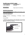
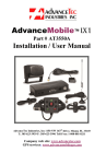
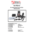
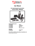
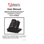
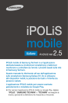
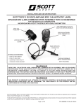
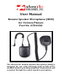
UserManual
RemoteSpeakerMicrophone(RSM)
forVerizonPhones
PartNo.AT8418A
TheAdvanceTecRemoteSpeakerMicrophone(RSM)is
designed for use with Verizon® Push‐to‐Talk (PTT)
enabledhandsetprovidingamplifiedtransmissionand
receptionthroughtheremotespeaker/microphone.
The RSM Part # AT8418A includes:
1.Part#AT8414A Speaker/Microphone
2.Part#AT8419A ControlModule
3.Part#AT8417A
CoilCable
OptionalExtras
Part#AT8416A
ReplacementLi‐IonBattery
IMPORTANTPhoneSetting.
Prior to attempting to use the RSM, the TTY feature in the
phonemustbeturnedOFF.
OnthePhoneMENUgoto:
Settings and Tools > Call Settings > TTY Mode > Select
TTYOFF
SetupofRSM
1.Plugthe2pinconnectorattheendofthecoilcordofthe
speaker/microphone into the corresponding socket on the
topcorneroftheControlModule.
2PinConnector
2PinSocket
2
2. Clip the Speaker/Microphone onto the lapel or other
convenientplaceontheusersclothing.
3.CliptheControlModuleontotheuser’sbelt.
4.ConnecttheControlModuletothehandsetusingthecoil
cord supplied, via the audio socket of the handset and the
correspondingaudiosocketontheControlModule.
OperatingtheRSM
1.PressthePTTonthesideoftheSpeaker/Microphoneand
speaktowardsthespeaker/microphonetotransmit.
2. Release the PTT button of the speaker/microphone to
listen. The audio will be heard from the
speaker/microphone.
ChargingtheControlModule
1.TheControlModulehasaninternalrechargeableLithium
Ionbatterywhich,likethephone,requiresregularcharging.
2. Before using for the first time, charge the battery in the
ControlModulefor24hours.
3.Usethepowersupply,suppliedwithyourphonetocharge
the Control Module. If the connector on the power supply
supplied with your phone is not a Micro USB, it will be
necessary for you to purchase a conversion connector to
converttheconnectortoaMicroUSBconnector,orpurchase
a power supply with a Micro USB connector. This type of
conversion connector or power supply with Micro USB
connectorisreadilyavailablefromyourlocalphonesupply
store.
LEDindicatoroftheControlModule
TheLEDindicatorontheControlModuleismulticolored.
1. When the Control Module is connected to the power
supply and the power supply is plugged into an AC outlet,
theLEDwilllightRED.
3
When the internal battery in the Control Module is fully
chargedtheLEDwillturnfromREDtoGREEN.
ReplacingthebatteryintheControlModule
1.IfafterfullychargingtheControlModule,theRSMwillnot
keep powered through out the day, the internal battery in
theControlModulemayneedtobereplaced.
2. To replace the internal battery, remove the belt clip on
the Control Module by pressing down the metal clip lever
underthebeltclipandslidethebeltclipout.
2. Remove the 2 silver screws holding the back of the
ControlModuleinplaceandremovetheback.
3. Unplug the battery and replace with a new battery
availablefromAdvanceTec(Part#AT8416A).
WARNING
DonotreplacetheinternalbatteryintheControlModulewith
anybatteryotherthanPart#AT8416AfromAdvanceTec.Any
other battery may cause harm to the Control Module’s
electronicsandcouldbeafirehazard
1150NW163rdDrive,Miami,FL33169
T:305‐623‐3939F305‐623‐3996
www.advancetec.com
4