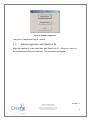
1
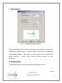
User guide for Programmable Multi IO (MultiIO version 1.10) 2010-05-17 Cristal Contrôles Ltée 2025 Lavoisier, Local 135 Québec, (Québec) Canada G1N 4L6 Tél 418-681-9590 Fax 418-681-7393 http://www.cristalcontrols.com Table of contents 1. Introduction .................................................................................................... 4 2. Requirement .................................................................................................. 4 3. Installation and registration ............................................................................ 5 3.1. Software registration with NanoTool 64 ................................................... 6 3.2. Software registration with LonMaker for Windows ................................... 8 4. Startup ........................................................................................................... 9 5. Input or output selection .............................................................................. 11 6. Input configuration ....................................................................................... 11 6.1. Physical input type ................................................................................. 12 6.2. Temperature offset ................................................................................ 12 6.3. Input filter ............................................................................................... 12 7. Output configuration .................................................................................... 13 7.1. Physical output type ............................................................................... 13 7.2. Calcul mode ........................................................................................... 14 7.3. Associated input .................................................................................... 15 7.4. Set point................................................................................................. 16 7.5. Proportional band (or hysteresis) ........................................................... 16 7.6. Output filter ............................................................................................ 16 8. Card update ................................................................................................. 17 9. Hardware test mode .................................................................................... 17 2010-05-17 Cristal Contrôles Ltée 2025 Lavoisier, Local 135 Québec, (Québec) Canada G1N 4L6 Tél 418-681-9590 Fax 418-681-7393 http://www.cristalcontrols.com 2 Table of figures Figure 1 - Programmable Multi IO software .......................................................... 4 Figure 2 - Software registration ............................................................................. 6 Figure 3 - Registration with NanoTool 64 .............................................................. 7 Figure 4 - Copy of files .xif et .xfb......................................................................... 8 Figure 5 - Registration with LonMaker for Windows .............................................. 9 Figure 6 - Plug-in startup with NanoTool 64 ........................................................ 10 Figure 7 - Plug-in startup with LonMaker for Windows ........................................ 10 Figure 8 - Input or output selection ..................................................................... 11 Figure 9 - Input configuration .............................................................................. 12 Figure 10 - Output configuration ......................................................................... 13 Figure 11 - Calcul Mode example ....................................................................... 15 Figure 12 - Card update buttons ......................................................................... 17 Figure 13 – Test Interface ................................................................................... 18 Figure 14 – Updating Window ............................................................................. 18 2010-05-17 Cristal Contrôles Ltée 2025 Lavoisier, Local 135 Québec, (Québec) Canada G1N 4L6 Tél 418-681-9590 Fax 418-681-7393 http://www.cristalcontrols.com 3 1. Introduction Figure 1 - Programmable Multi IO software Programmable Multi IO is a software that allows inputs, outputs and functioning configuration of Multi IO card. To use this software, card had to be installed with corresponding software. This software is also a “plug in” and it function with another software. Contact Cristal Controls technical support for more information. 2. Requirement Programmable Multi IO work with these Microsoft Windows version : 2010-05-17 Cristal Contrôles Ltée 2025 Lavoisier, Local 135 Québec, (Québec) Canada G1N 4L6 Tél 418-681-9590 Fax 418-681-7393 http://www.cristalcontrols.com 4 Windows 2000; Windows XP; Windows Vista. The software also needs one of these software because it’s a “plug-in” software: NanoTool 64; LonMaker for Windows. 3. Installation and registration To install Programmable Multi IO software, run installation software called « setup.exe » et follow instructions. Normally, installation software saves the plug-in in the LNS plug-in list. If the plug-in name doesn’t appear in the list in the registration in NanoTool 64 or LonMaker for Windows, registration would be completed manually. “MultiIO.exe” file has to be executed to complete registration manually. The next screen will appear: 2010-05-17 Cristal Contrôles Ltée 2025 Lavoisier, Local 135 Québec, (Québec) Canada G1N 4L6 Tél 418-681-9590 Fax 418-681-7393 http://www.cristalcontrols.com 5 Figure 2 - Software registration Just push « Registration Plug-in » button. 3.1. Software registration with NanoTool 64 After the creation of a new data base with NanotTool 64, « Plug-Ins » option in the software menu has to be selected. The next screen will appear. 2010-05-17 Cristal Contrôles Ltée 2025 Lavoisier, Local 135 Québec, (Québec) Canada G1N 4L6 Tél 418-681-9590 Fax 418-681-7393 http://www.cristalcontrols.com 6 Figure 3 - Registration with NanoTool 64 To complete registration, choose « Cristal Controls Programmable MultIO (Version 1.1) » and push « Register » button. If the plug-in name doesn’t appear in the list, it didn’t record during installation. Just follow instruction at the beginning of this section. If the next screen appears, files “MultiIO.xif”, “MultiIO.xfb”, « MultiIO2.xif » and « MultiIO2.xfb » must be copied in the folder “c:\lonworks\import\Cristal”. Programmable MultiIO is now ready to use. 2010-05-17 Cristal Contrôles Ltée 2025 Lavoisier, Local 135 Québec, (Québec) Canada G1N 4L6 Tél 418-681-9590 Fax 418-681-7393 http://www.cristalcontrols.com 7 Figure 4 - Copy of files .xif et .xfb 3.2. Software registration with LonMaker for Windows After the creation of a new data base with LonMaker for Windows, « LonMaker » option in the software main menu has to be selected and option “Network Properties” in the next menu. In the tab “Plug-In Registration”, choose « Cristal Controls Programmable MultIO (Version 1.1) » and push “Add” button. If the plug-in name doesn’t appear in the list, it didn’t record during installation. Just follow instruction at the beginning of this section. Registration will be completed when the window will be closed. If the screen on Figure 4 appears, files “MultiIO.xif”, “MultiIO.xfb”, “MultiIO2.xif” and “MultiIO2.xfb” must be copied in the folder “c:\lonworks\import\Cristal”. Programmable MultiIO is now ready to use 2010-05-17 Cristal Contrôles Ltée 2025 Lavoisier, Local 135 Québec, (Québec) Canada G1N 4L6 Tél 418-681-9590 Fax 418-681-7393 http://www.cristalcontrols.com 8 Figure 5 - Registration with LonMaker for Windows 4. Startup To use the software, a « device » had to be installed with corresponding MultiIO software. If LonMaker for Windows is used, a “functional block” had to be also created. Look at the LonMaker for Windows user manual for more information. To start the plug-in with NanoTool 64 or with LonMaker for Windows, “device” shortcut or “functional block” shortcut have to be selected. With the right button 2010-05-17 Cristal Contrôles Ltée 2025 Lavoisier, Local 135 Québec, (Québec) Canada G1N 4L6 Tél 418-681-9590 Fax 418-681-7393 http://www.cristalcontrols.com 9 of the mouse, “Plug-Ins” option in the menu has to be chosen. The next screen will appear. Figure 6 - Plug-in startup with NanoTool 64 Figure 7 - Plug-in startup with LonMaker for Windows Select « [Config Multi I-O] Configure MultiIO » choice and push “OK” button to start the software in configuration mode. Alternatively, if you select « [Config 2010-05-17 Cristal Contrôles Ltée 2025 Lavoisier, Local 135 Québec, (Québec) Canada G1N 4L6 Tél 418-681-9590 Fax 418-681-7393 http://www.cristalcontrols.com 10 Multi I-O] Test MultiIO », the software will start in a mode to test the inputs and the outputs of the MultiIO controller. 5. Input or output selection Multi IO card has 8 physical inputs and outputs. Each of them is configurable separately. Input or output to configure can be choose in the Combo box “Input/Output Number”. If an input is chosen, “Input Configuration” group will be accessible and inputs values will be able to change. If an output is chosen, “Output Configuration” will be accessible and outputs values will be also able to change. Figure 8 - Input or output selection 6. Input configuration For each physical input, type of input can be specified. If a temperature sensor is connected to input, an offset can be entered. 2010-05-17 Cristal Contrôles Ltée 2025 Lavoisier, Local 135 Québec, (Québec) Canada G1N 4L6 Tél 418-681-9590 Fax 418-681-7393 http://www.cristalcontrols.com 11 Figure 9 - Input configuration 6.1. Physical input type Combo box « Physical Input Type » allows specifying physical input type. An input can be configured as this following type: V10, V5, mA420, K10, contact and mA020. 6.2. Temperature offset It is possible to apply a temperature offset if chosen input is K10 type. This offset can be positive or negative and it will be applied directly on value red by temperature probe. Be careful that only K10 type input support offset temperature. 6.3. Input filter Edit box « Filter Constant » allows to enable a filter on the input’s network variable’s value. This value is in seconds and writing zero as the filter’s constant disable the filter. The filter constant value represents the time taken for a variation of 63.3% toward the final value of the network variable’s value. Example 2010-05-17 Cristal Contrôles Ltée 2025 Lavoisier, Local 135 Québec, (Québec) Canada G1N 4L6 Tél 418-681-9590 Fax 418-681-7393 http://www.cristalcontrols.com 12 using 15 seconds as the filter’s constant: when the read value of the input changes from 0% to 100%, the network variable’s value will take 15 seconds to change from 0% to 63.3%. 30 seconds after the variation the network variable’s value will be 86.5% and 45 seconds after the variation the network variable’s value will be 95%. 7. Output configuration Card outputs can be configured with different parameters. As inputs, physical type can be specified. Calcul mode, associated input, set point and proportional band (or hysteresis) have to be configured. Each output has its own parameters. Figure 10 - Output configuration 7.1. Physical output type Combo box « Physical Output Type » allows specifying physical output type. An output can be configured as this following type: V10, V5, mA420, contact, mA020 and pwm. 2010-05-17 Cristal Contrôles Ltée 2025 Lavoisier, Local 135 Québec, (Québec) Canada G1N 4L6 Tél 418-681-9590 Fax 418-681-7393 http://www.cristalcontrols.com 13 7.2. Calcul mode Combo box « Calcul Mode » allows selecting output calcul mode. Four choices are available: On/Off (ON_OFF), inverted On/Off (ON_OFF_INV), proportional (PROP), invert proportional (PROP_INV). On/Off mode is a heating mode. Output state will become On when input value goes under lower hysteresis value. When input value is over higher hysteresis value, output state becomes Off. Inverted On/Off mode is a cooling mode. Output state turn to On when input value goes over higher hysteresis value and becomes Off when input value is under lower hysteresis value. Proportional mode is a heating mode as On/Off mode but output value doesn’t have only two states. Output value can be between 0 and 100%. More the input value decreases, more than output value will be closer than 100%. Inverted proportional mode is also a cooling mode as inverted On/Off mode. Unlike proportional mode, more than input value decreases, more than output value will be closer to 0%. Here is an example of the four available modes where set point is fixed to 21.0 C and proportional band to 2.0 C. 2010-05-17 Cristal Contrôles Ltée 2025 Lavoisier, Local 135 Québec, (Québec) Canada G1N 4L6 Tél 418-681-9590 Fax 418-681-7393 http://www.cristalcontrols.com 14 Temperature On/Off (heating) Inv. On/Off Proportionnal Inv. proportionnal (cooling) (heating) (cooling) 22.0 C Off On 0% 100% 21.5 C Keep state Keep state 25% 75% 21.0 C Keep state Keep state 50% 50% 20.5 C Keep state Keep state 75% 25% 20.0 C On Off 100% 0% Figure 11 - Calcul Mode example 7.3. Associated input Combo box “Input” allows selecting an input to associate to an output. It is possible to associate an output to a physical input and a network variable. For network variable, it is possible to choose between temperature variable (SNVT_temp_p) and percent variable (SNVT_lev_percent). So, these choices are available: Input 1 to Input 8 for physical inputs, Network Percent 1 to Network Percent 8 for network percent input variable and Network Temperature 1 to Network Temperature 8 for network temperature input variable. Note that an input can be associated to more than one output. 2010-05-17 Cristal Contrôles Ltée 2025 Lavoisier, Local 135 Québec, (Québec) Canada G1N 4L6 Tél 418-681-9590 Fax 418-681-7393 http://www.cristalcontrols.com 15 7.4. Set point Edit box « Set point » allows entering set point that will be used in the calcul output value. Type of set point depends of input type associated with the output. If the output is associated to a network temperature variable (“Network Temperature”) or to a K10 physical type, set point will be a temperature set point. If the output is associated to a network percent variable or to any other type of physical input, set point will be a percent set point. 7.5. Proportional band (or hysteresis) Edit box « Hysteresis » allows to enter proportional band or hysteresis value. Type of value depends of selected calcul mode. As the set point, type of value to enter will change in function of input associated output. A temperature or percent value will be entered. 7.6. Output filter Edit box « Filter Constant » allows to enable a filter on the output variation. This value is in seconds and entering zero as the filter’s constant disable the filter. The filter constant value represents the time taken for a variation of 63.3% forward the final value of the output. Example using 15 seconds as the filter’s constant: when the Multi-IO drives the value of the output from 0% to 100%, the output will take 15 seconds to change from 0% to 63.3%. 30 seconds after the variation the output’s value will be 86.5% and 45 seconds after the variation the output’s value will be 95%. 2010-05-17 Cristal Contrôles Ltée 2025 Lavoisier, Local 135 Québec, (Québec) Canada G1N 4L6 Tél 418-681-9590 Fax 418-681-7393 http://www.cristalcontrols.com 16 8. Card update Figure 12 - Card update buttons To update Multi IO card, button « OK » or « Update » must be use. Button “OK” will update card and the software will be closed. Button “Update” will update card but the software won’t be closed. Button “Cancel” will close the software but Multi IO card won’t be update. Modifications will be lost. Reboot is needed for a good functioning of the card. The software will advise and will reboot the card. 9. Hardware test mode This is the hardware test interface of the Multi IO card. 2010-05-17 Cristal Contrôles Ltée 2025 Lavoisier, Local 135 Québec, (Québec) Canada G1N 4L6 Tél 418-681-9590 Fax 418-681-7393 http://www.cristalcontrols.com 17 Figure 13 – Test Interface This interface allows the manual control of the card’s outputs and to monitor the values read by the inputs. The “Output” sections allow the manual control of individual output (“Output #X” sections) or of all the outputs (“All Outputs” section). The “Output Type” section allows the configuration of the outputs type and the “Input Type” the configuration of the inputs type. The “Inputs” section shows the inputs read values. They are refreshed every 2 seconds. When changing the outputs or inputs types the following window appears: Figure 14 – Updating Window This window shows the reconfiguration progression. When the reconfiguration is completed, a reset request is sent to the Multi IO card to ensure the application of the new configuration. 2010-05-17 Cristal Contrôles Ltée 2025 Lavoisier, Local 135 Québec, (Québec) Canada G1N 4L6 Tél 418-681-9590 Fax 418-681-7393 http://www.cristalcontrols.com 18 The Multi IO card configuration is saved when the test interface is opened and the saved configuration is reapplied when closing the test interface. “Figure 14 – Updating Window” appears on both operations. 2010-05-17 Cristal Contrôles Ltée 2025 Lavoisier, Local 135 Québec, (Québec) Canada G1N 4L6 Tél 418-681-9590 Fax 418-681-7393 http://www.cristalcontrols.com 19 Legal Disclaimer Any representation or reproduction, in whole or in part, made without the permission of Cristal Controls Ltd, is unlawful. Such unlawful representation or reproduction, made by any means, would be an infringement of copyright punished under the provisions of the copyright law. All products are registered trademarks of their respective companies. 2010-05-17 Cristal Contrôles Ltée 2025 Lavoisier, Local 135 Québec, (Québec) Canada G1N 4L6 Tél 418-681-9590 Fax 418-681-7393 http://www.cristalcontrols.com 20 2 YEAR LIMITED WARRANTY CRISTAL CONTROLS warrants to the original user that its products will be free from defects in materials and workmanship for a period of two years after the date CRISTAL CONTROLS shipped such products. If any of CRISTAL CONTROLS’ products is found to be defective in material or workmanship during the applicable warranty period, CRISTAL CONTROLS' liability shall be limited to the repair or replacement of the product, or the refund of the purchase price, at CRISTAL CONTROLS’ discretion. CRISTAL CONTROLS shall not be held liable for any costs or expenses, whether direct or indirect, associated with the installation, removal or re-installation of any defective product. CRISTAL CONTROLS’ limited warranty shall not be effective unless there is compliance with all installation and operating instructions furnished by CRISTAL CONTROLS, if the products have been modified or altered without the written consent of CRISTAL CONTROLS, or if such products have been subject to accident, misuse, mishandling, tampering, negligence, or improper maintenance. Any warranty claim must be submitted to CRISTAL CONTROLS in written form within the stated warranty period. CRISTAL CONTROLS’ limited warranty is made in lieu of, and CRISTAL CONTROLS disclaims all other warranties, whether expressed or implied, including but not limited to any implied warranty of the products. CRISTAL CONTROLS shall not, under any circumstances, be liable for any direct, indirect, accidental, special, or consequential damage (including but not limited to loss of profits, revenues, or business opportunities) or damage or injury to persons or property in any way related to the manufacture or the use of its products. The exclusion applies regardless of whether such damages are sought based on breach of warranty, breach of contract, negligence, strict liability in tort, or any other legal theory, even if CRISTAL CONTROLS was noticed of the possibility of such damages. By purchasing CRISTAL CONTROLS’ products, the purchaser agrees to the terms and conditions of this limited warranty. Cristal Contrôles Ltée 2025 Lavoisier, Local 135 Québec, (Québec) Canada G1N 4L6 Tél 418-681-9590 Fax 418-681-7393 http://www.cristalcontrols.com 2010-05-17 21