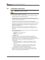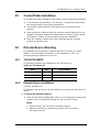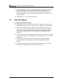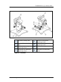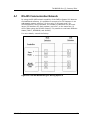
1
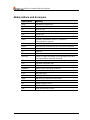
Quasar 900 Open-Path Gas Detection System User's and Maintenance Manual Factory Mutual Class I Div. 1 Groups B, C, D Class II Div. 1 Groups E, F, G ATEX, IECEx Ex II 2 (2) GD, Ex d e ib [ib Gb] IIB+H2 T4 Gb Ex tb IIIC T135°C Db Document Ref: TM 888200, Rev. I, January 2014 218 Little Falls Rd., Cedar Grove, NJ 07009 USA; Phone: +1 (973) 239 8398 Fax: +1 (973) 239 7614 Web-Site: www.spectrex.net ; Email: [email protected] SafEyeTM Quasar 900 Gas Detector ii Legal Notice The SafEye monitoring system described in this document is the property of Spectrex, Inc. No part of the hardware, software or documentation may be reproduced, transmitted, transcribed, stored in a retrieval system, or translated into any language or computer language, in any form or by any means, without prior written permission of Spectrex, Inc. While great efforts have been made to assure the accuracy and clarity of this document, Spectrex, Inc. assumes no liability resulting from any omissions in this document, or from misuse of the information obtained herein. The information in this document has been carefully checked and is believed to be entirely reliable with all of the necessary information included. Spectrex Inc. reserves the right to make changes to any products described herein to improve reliability, function, or design, and reserves the right to revise this document and make changes from time to time in content hereof with no obligation to notify any persons of revisions or changes. Spectrex, Inc. does not assume any liability arising out of the application or any use of any product or circuit described herein; neither does it convey license under its patent rights or the rights of others. Warning: This manual should be carefully read by all individuals who have or will have responsibility for using, maintaining or servicing the product. The Source and Detector are not field-repairable due to the meticulous alignment and calibration of the sensors and the respective circuits. Do not attempt to modify or repair the internal circuits or change their settings, as this will impair the system's performance and void the Spectrex, Inc. Product warranty. . Legal Notice iii SafEyeTM Quasar 900 Gas Detector Release History Rev Date Revision History Prepared by Approved by F February First Release Ian Buchanan Eric Zinn G June 2013 Second release Ian Buchanan Eric Zinn H August 2013 Third Release Ian Buchanan Eric Zinn I January 2014 Fourth Release Ian Buchanan Eric Zinn iv Release History About this Guide This manual describes the Quasar 900 Open-Path Gas Detection System and its features and provides instructions on the installation, operation and maintenance. This guide includes the following chapters and appendices: Chapter 1, Scope, provides a general introduction and overview of the product and the guide, with a brief description of its content. Chapter 2, Technical Description, describes the Detector’s theory of operation. Chapter 3, Operation Mode, describes the Detector’s operation modes, user interface and indications. Chapter 4, Technical Specifications, describes the Detector’s electrical, mechanical and environmental specifications. Chapter 5, Installation Instructions, describes how to install the Detector, including wiring and mode settings. Chapter 6, Operating Instructions, describes the operating instructions and power-up procedures. Chapter 7, Maintenance Instructions, contains the maintenance and support procedures. Chapter 8, Troubleshooting, describes the solutions to problems that may arise with the Detector. Appendix A, Wiring Option Configurations, provides wiring diagrams for installation. Appendix B, Accessories, provides a list of accessories available for the Quasar 900 Open-Path Gas Detection System. Appendix C, SIL-2 Features, details the special conditions to comply with the requirements of EN 61508 for SIL-2. About this Guide v SafEyeTM Quasar 900 Gas Detector Abbreviations and Acronyms vi Abbreviation Meaning ATEX Atmosphere Explosives AWG American Wire Gauge BIT Built In Test EMC Electromagnetic Compatibility EOL End of Line FOV Field of View HART Highway Addressable Remote Transducercommunication protocol IAD Immune at Any Distance IECEx International Electrotechnical Commission Explosion IPA Isopropyl Alcohol IR Infrared JP5 Jet Fuel Latching Refers to relays remaining in the ON state even after the ON condition has been removed LED Light Emitting Diode LPG Liquefied Petroleum Gas mA MilliAmps (0.001 amps) MODBUS Master-slave messaging structure N.C. Normally Closed N.O. Normally Open N/A Not Applicable NFPA National Fire Protection Association NPT National Pipe Thread SIL Safety Integrity Level UNC Unified Coarse Thread VAC Volts Alternating Current Abbreviations and Acronyms Table of Contents Quasar 900 Open-Path Gas Detection System User's and Maintenance Manual ....................................................................... i Legal Notice .................................................................................................... iii Release History ............................................................................................... iv About this Guide.............................................................................................. v Abbreviations and Acronyms ............................................................................. vi 1 Scope ......................................................................................................... 1 1.1 2 Product Overview ................................................................................... 1 Technical Description ................................................................................ 3 2.1 Features ............................................................................................... 3 2.2 Applications........................................................................................... 4 2.3 Principle of Operation ............................................................................. 4 2.3.1 Definitions of Terms ......................................................................... 4 2.3.2 Spectral Finger Print ......................................................................... 4 2.3.3 Optical Path .................................................................................... 5 2.3.4 Microprocessor Based ....................................................................... 5 2.3.5 Gas Sensitivity ................................................................................ 5 2.3.6 Gas Calibration ................................................................................ 5 2.3.7 Flash Source ................................................................................... 5 2.3.8 Heated Optics .................................................................................. 6 2.3.9 HART Protocol ................................................................................. 6 2.3.10 Handheld Unit ................................................................................. 6 2.3.11 Modbus RS-485 ............................................................................... 7 2.3.12 Tilt Mount ....................................................................................... 7 2.4 Product Certification ............................................................................... 7 2.4.1 ATEX, IECEx .................................................................................... 7 2.4.2 FM / FMC ........................................................................................ 8 2.4.3 SIL-2.............................................................................................. 8 2.4.4 Functional Test ................................................................................ 8 2.5 Models and Types .................................................................................. 8 2.6 Description ............................................................................................ 9 2.6.1 Flash Source Unit ............................................................................ 10 2.6.2 Detector Unit .................................................................................. 11 Table of Contents vii SafEyeTM Quasar 900 Gas Detector 3 Operating Modes...................................................................................... 13 3.1 Operational Modes ................................................................................13 3.1.1 Normal Mode .................................................................................. 13 3.1.2 Maintenance Call Mode (3mA Output) ................................................ 13 3.1.3 Fault Mode ..................................................................................... 14 3.1.4 Zero Calibration Mode (1mA Output) ................................................. 14 3.2 Visual Indicators ...................................................................................15 3.3 Output Signals ......................................................................................15 3.3.1 0-20mA Current Output ................................................................... 15 3.3.2 RS-485 Interface ............................................................................ 16 3.4 4 System Setup .......................................................................................16 3.4.1 Detection Function Programming ...................................................... 16 3.4.2 Detection Setup Function ................................................................. 17 3.4.3 Detector Default Setup .................................................................... 18 Technical Specifications ........................................................................... 19 4.1 General Specifications ...........................................................................19 4.2 Electrical Specifications ..........................................................................20 4.2.1 Power Consumption ........................................................................ 20 4.2.2 Electrical input protection ................................................................ 20 4.2.3 Electrical outputs ............................................................................ 20 4.3 Mechanical Specifications .......................................................................21 4.4 Environmental Specifications ..................................................................22 5 4.4.1 High Temperature ........................................................................... 22 4.4.2 Low Temperature ............................................................................ 22 4.4.3 Humidity ........................................................................................ 22 4.4.4 Salt and Fog ................................................................................... 22 4.4.5 Water and Dust .............................................................................. 22 4.4.6 Shock and Vibration ........................................................................ 22 4.4.7 Electromagnetic Compatibility (EMC) ................................................. 23 Installation Instructions .......................................................................... 25 5.1 Introduction .........................................................................................25 5.2 General Considerations ..........................................................................25 viii 5.2.1 Personnel ....................................................................................... 25 5.2.2 Tools Required................................................................................ 25 5.2.3 Site Requirements .......................................................................... 26 Table of Contents TM 888200 Rev (I), January 2014 6 5.2.4 The Source and Detector ................................................................. 26 5.2.5 Guidance Tips for Gas Detector Locations........................................... 26 5.3 Preparations for Installation ...................................................................26 5.4 Certification Instructions ........................................................................28 5.5 Conduit/Cable Installation ......................................................................29 5.6 Detector/Source Mounting ......................................................................29 5.6.1 Tilt Kit P/N 888270.......................................................................... 29 5.6.2 Detector/Source Installation ............................................................. 29 5.7 Detector Wiring ....................................................................................30 5.8 Detector Terminal Wiring .......................................................................34 5.9 Flash Source Wiring...............................................................................34 5.9.1 Wiring ........................................................................................... 34 5.9.2 Terminal Wiring .............................................................................. 35 Operating Instructions ............................................................................ 37 6.1 SafEye Operation ..................................................................................37 6.2 Alignment of Unit ..................................................................................37 6.3 Powering up the System ........................................................................38 6.4 Safety Precautions ................................................................................39 6.5 Signal Verification .................................................................................39 6.5.1 7 8 Signal Values Limitation ................................................................... 39 6.6 Zero Calibration ....................................................................................40 6.7 Functional Check of Unit ........................................................................41 Maintenance Instructions ........................................................................ 43 7.1 General Maintenance .............................................................................43 7.2 Periodic Maintenance .............................................................................43 7.2.1 Routine Optical Surface Cleaning ...................................................... 44 7.2.2 Signal Verification ........................................................................... 44 7.2.3 Function Check of Unit ..................................................................... 44 Troubleshooting ...................................................................................... 45 Appendices .................................................................................................... 47 A Wiring Configurations .............................................................................. 49 A.1 RS-485 Communication Network .............................................................53 Table of Contents ix SafEyeTM Quasar 900 Gas Detector B C Accessories .............................................................................................. 55 B.1 Tilt Mount P/N 888270 ...........................................................................55 B.2 Pole Mount (U-Bolt 5 inch) P/N 799225 ....................................................55 B.3 Commissioning Kit P/N 888247 ...............................................................55 B.4 RS485 Hand-Held Diagnostic Unit P/N 799810 ..........................................55 B.5 HART Hand-Held Diagnostic Unit P/N 888810 ...........................................56 B.6 HART Hand-Held Harness Kit P/N 888815 ................................................56 B.7 USB/RS485 Harness Converter Kit P/N 794079-8 ......................................56 B.8 Mini Laptop Kit P/N 777820 ....................................................................56 B.9 Sunshade P/N 888263 ...........................................................................56 SIL-2 Features ......................................................................................... 57 C.1 Safety Relevant Parameters for the Quasar 900 Open Path Gas Detector .....57 C.2 General Conditions for Safe Use ..............................................................58 Technical Support ......................................................................................... 59 x Table of Contents TM 888200 Rev (I), January 2014 List of Figures Figure 1: P/N Definition of Quasar 900 .................................................................. 9 Figure 2: Flash Source ....................................................................................... 10 Figure 3: Detector ............................................................................................. 11 Figure 4: Tilt Mount ........................................................................................... 31 Figure 5: Detector and Tilt Mount Assembly .......................................................... 32 Figure 6: Detector with Cover Removed ............................................................... 33 Figure 7: Source with Cover Removed ................................................................. 35 Figure 8: Magnetic Mode Selector ........................................................................ 40 Figure 9: Detector Wiring Terminal ...................................................................... 49 Figure 10: Source Wiring Terminal ...................................................................... 50 Figure 11: 0-20mA Sink 4-Wire........................................................................... 51 Figure 12: 0-20mA Non-isolated Sink 3-Wire ........................................................ 51 Figure 13: 0-20mA Source 3-Wire ....................................................................... 52 Figure 14: RS-485 Networking for Wiring Option 3 ................................................ 53 List of Figures xi SafEyeTM Quasar 900 Gas Detector List of Tables Table 1: Gas Concentrations Measurement Terms .................................................. 4 Table 2: Model Numbers and Installation Distances ................................................ 8 Table 3: Detector LED Indications ....................................................................... 15 Table 4: Source LED Indications .......................................................................... 15 Table 5: Standard (default) 0-20mA Current for the Gas Channel ............................ 16 Table 6: Detector Default Set Up ......................................................................... 18 Table 7: Source Default Set Up ........................................................................... 18 Table 8: Detection Distance Range ...................................................................... 19 Table 9: Detector and Source Maximum Power Consumption .................................. 20 Table 10: Tilt Mount Kit...................................................................................... 29 Table 11: Wiring Options .................................................................................... 34 Table 12: Flash Source Wiring Options ................................................................. 35 Table 13: Maintenance Channels Limit Values ....................................................... 39 Table 14: Troubleshooting .................................................................................. 45 xii List of Tables 1 Scope ➣ In this chapter… Product Overview 1.1 page 1 Product Overview The SafEye Quasar 900 IR Open-Path Gas Detector employs an advanced Xenon Flash Source and integrated electronics package, both housed in improved, Stainless steel housings to provide high quality and performance, fast response, line of sight gas monitoring. This high quality is backed by 3 years warranty for the complete SafEye system and 10 years for the Xenon Flash source bulb. Quasar 900 detects ambient combustible gases over a path length of up to 660ft. (200 m), even in harsh environments where dust, fog, rain, snow or vibration can cause a high reduction of signal. The SafEye Quasar 900 can maintain operation in up to 90% signal obscuration and ±0.5 degree of misalignment. Quasar 900 is manufactured only in stainless steel with heated optical window to improve performance in icing, snow, and condensation conditions. The programmable functions are available through a RS 485 or HART port used with Host software supplied by Spectrex and a standard PC or an I.S handheld unit. The Quasar Source and Detector unit enclosures are ATEX and IECEx approved Exd flameproof with an integral segregated rear, Exe terminal compartment which avoids exposure of the sensors and electronics to surrounding environment. The Detector also has a plug interface for connection to handheld PC or HART handheld, which is intrinsically safe. Hence the combined approval - Ex d e ib [ib Gb] IIB+H2 T4 Gb, Ex tb IIIC T135°C Db IP66. This manual consists of a full description of the Detector and its features. It contains instructions on the installation, operation and maintenance. To use the WinHost software to change the required functions and for maintenance, refer to Manual TM 888050 for instructions To use the I.S Handheld Unit to change the required functions and for maintenance, refer to Manual TM 799060 for instructions. To use HART Protocol to change the required functions and for maintenance refer to Manual TM 888030. The HART can be connected on the 0-20mA line or through the IS port for setting Product Overview 1 SafEyeTM Quasar 900 Gas Detector 2 Product Overview 2 Technical Description ➣ In this chapter… 2.1 page 3 Applications page 4 Principle of Operation page 4 Product Certification page 7 Models and Types page 8 Description page 9 Features Long Range Gas Detection up to 660ft (200m) Simultaneous detection of C1-C8 flammable gases High Sensitivity and fast response to Hydrocarbon gases Heated optics to improve performance in icing, condensation and snow conditions Continuous operation in extreme and harsh environmental Conditions Solar blind and immune to industrial environments Withstands extreme vibration conditions Standard 0-20 mA Output HART Protocol: Communication Protocol RS-485 Output Modbus compatible for PC Communication Network for a maximum of 247 systems Simple one person installation, alignment, and calibration ATEX & IECEx per EX II 2 GD, Ex d e ib [ib Gb] IIB+H2 T4 Gb, Ex tb IIIC T135°C Db IP66 TUV approved per SIL2 requirements FM / FMC approved per: Class I Div. 1 Group B, C and D; Class II/III Div. 1 Group E, F and G Functional approved per FM 6325 Functional tested by FM per EN60079-29-4 Programmable configuration via the handheld unit Fast connection to I.S. approved handheld diagnostic/calibration unit Features Features (3mA) “maintenance call” Warranty 3 years for the complete SafEye system Warranty 10 years for Xenon Flash bulb 3 SafEyeTM Quasar 900 Gas Detector 2.2 Applications The Quasar 900 system may be used to monitor flammable gas concentration in various applications, such as: 2.3 Petrochemical, pharmaceutical and other chemical storage and production areas. Flammable and toxic chemical storage sites and hazardous waste disposal areas. Refineries, oil platforms, pipelines, refueling stations and fuel storage facilities. Hazardous loading docks, transportation depots and shipping warehouses Engine rooms Compressor and pumping stations Test cells LNG-LPG Systems Offshore Floating Production Storage and Shipping vessels (FPSO), and fixed oil rigs. Principle of Operation The Quasar system detects gases through a dual spectral range monitoring, analyzing the absorption of radiation caused by gases in the atmosphere and comparing it (ratio) to background atmospheric absorption. 2.3.1 Definitions of Terms The following list defines gas concentrations measurement terms that are used in this manual: Table 1: Gas Concentrations Measurement Terms 2.3.2 Term Description LEL Lower Explosive Limit: The minimum concentration of a substance (gas/vapor) in air mixture that can be ignited. This mixture is different for every gas/vapor, measured in % of LEL. LEL.m Integral of Concentration in LEL units (1 LEL = 100% LEL) and the operation distance in meters (m). Spectral Finger Print Each hazardous material is detected at a specific wavelength selected according to its specific spectral absorption or "finger print". The detection process involves two separate filters, one transmitting radiation that is absorbed by a particular gas and one that is not sensitive to it. 4 Applications TM 888200 Rev (I), January 2014 2.3.3 Optical Path The presence of hazardous airborne vapors, gases, or aerosols in a monitored area is detected when the defined substance crosses/enters the optical path between the radiation source unit and the detector. Hazardous gases /vapors present in the atmosphere cause absorption of the radiation pulse in the optical path between the radiating source and the detector unit at some specific wavelengths. This causes a change in the signal intensity received by the detector, which is translated into an output related to the detector’s measuring scale. The system analyzes the defined open path at the spectral bands specific to the materials being monitored. The Automatic Gain Control (AGC) unit compensates for environmental disturbances such as fog, rain, etc., through a constant comparison with its dual spectral beam. 2.3.4 Microprocessor Based The incoming signals are analyzed by the built in microprocessor. A sophisticated mathematical algorithm calculates between the various functions of the detected signal thresholds. Statistics, ratio algorithms, data communications, diagnostics and other functions are performed. 2.3.5 Gas Sensitivity The SafEye Quasar 900 Model uses wavelengths around 2.3µ spectral band to measure air flammability potential between the source and detector. At this wavelength, all hydrocarbon materials have an absorption peak. This enables the detector to achieve both regular sensitivity of 0-5 LEL.m. The Quasar 900 detects hydrocarbon gases including methane, ethylene, propane, ethane, butane, and so on. 2.3.6 Gas Calibration The Quasar 900 has three calibrations that can be changed by function Setup: Gas 1 – 100% methane Gas 2 – 100% propane Gas 3 – 100% ethylene The full scale of methane and propane is 5 LEL.m. The full scale of ethylene is 8 LEL.m. 2.3.7 Flash Source The Xenon Flash Source was originally introduced in the first SafEye development and was designed to overcome false alarms, which were experienced by early generations of the open path system. The new SafEye Quasar 900 employs the latest generation of flash bulbs to provide even more power and extended operation life (10 years). Principle of Operation 5 SafEyeTM Quasar 900 Gas Detector 2.3.8 Heated Optics SafEye Quasar includes heated optics for the Detector and source. The heater increases the temperature of the optical surface by 5-8°F (3-5°C) above the ambient temperature to improve performance in icing, condensation and snow conditions. The heated optics is configured to automatically operate when the change in temperature requires the heating (default). However, the heated optics can be defined as one of the following modes: 1 Not operated (not an option on source unit) 2 On continuously 3 Automatic, per temperature change (default) See System Setup, page 16. When operated ‘per temperature change’, the user can define the start temperature below which the window will be heated (default 41°F (5°C)). This temperature can be defined between 32°F (0°C) to 122°F (50°C). The heating will stop when the temperature is 27°F (15°C) above the start temperature. 2.3.9 HART Protocol The Quasar 900 uses the HART Protocol. HART Communication is a bi-directional industrial field communication protocol used to communicate between intelligent field instruments and host systems. HART is the global standard for smart instrumentation and the majority of smart field devices installed in plants worldwide are HARTenabled. HART technology is easy to use and very reliable. Through the HART connection, the SafEye is able to perform: Detector set-up Detector troubleshooting Detector health and status For more details, refer to the HART Manual TM 888030. The HART communication can be connected on the 0-20mA line or through the IS connection with a standard Handheld loaded with our host software and a special harness. 2.3.10 Handheld Unit The I.S.-approved handheld diagnostics unit (Part no. 799810) is available to make installation and maintenance easier. This is an all-on-one diagnostic / calibration / interrogation plug-in unit that allows for one-person installation and maintenance. 6 Principle of Operation TM 888200 Rev (I), January 2014 The handheld unit can be used: 1 For on-site function programming and set up changes to the Detector. 2 During installation, the handheld unit will display all the detector’s parameters and confirm that the installation has been completed successfully. It is also required to perform the necessary Zero calibration function 3 For Maintenance and Trouble Shooting – The handheld unit will provide recommendation of maintenance action to overcome and optimize the Detector’s performance. For more details, refer to Manual TM 799060. 2.3.11 Modbus RS-485 For more advanced communications, the Quasar 900 has a RS-485 Modbuscompatible output that provides data communication from a network (up to 247 Detectors) to a host computer or universal controller for central monitoring. This feature enables easy maintenance, local and remote diagnostic tools. 2.3.12 Tilt Mount The new design stainless steel tilt mount provides a smaller installation footprint that can conform to limited space constraints, while the sturdy construction maintains alignment even in constant vibration. The improved ‘X’ and ‘Y’ axis worm-gear adjustments provide quick and easy alignment for installation and maintenance procedures. 2.4 Product Certification The open path Quasar 900 is approved for the following certification: 2.4.1 ATEX, IECEx, page 7 FM / FMC, page 8 SIL-2, page 8 Functional Test, page 8 ATEX, IECEx The Quasar 900 is ATEX approved per SIRA 12ATEX1212X and IECEx per IECEx SIR 12.0086X per: ATEX Ex II 2 GD Ex d e ib [ib Gb] IIB+H2 T4 Gb Ex tb IIIC T135°C Db IP66 T Ambient –55°C to +65°C This product is suitable to use in hazardous zones 1 and 2 with IIB+H2 group vapors present. Product Certification 7 SafEyeTM Quasar 900 Gas Detector 2.4.2 FM / FMC The Quasar 900 is approved to FM / FMC Explosion Proof per: Class I, Div. 1 Group B, C and D, T6 -58°F (-50°C) ≤ Ta ≤ 149°F (65°C) Dust Ignition Proof – Class II/III Div. 1, Group E, F and G. Ingress Protection – IP66 & IP68, NEMA 250 Type 6P. IP68 is rated for 2 meter depth for 45 minutes. 2.4.3 SIL-2 The Quasar 900 Is TUV approved for SIL2 requirements per IEC 61508. The alert condition according to SIL-2 can be implemented by alert signal via 0-20mA current loop. For more details and guidelines on configuring, installing, operating and servicing, see SIL-2 Features, page 57, and TUV report no. 968/EZ 619.00/13. 2.4.4 Functional Test The Quasar 900 was functional approved per FM 6325 The Quasar 900 was functional tested by FM per EN60079-29-4 2.5 Models and Types The Quasar 900 includes 4 models with the same detector and different source. That gives the ability to get detection at distances of 7-200m. Table 2: Model Numbers and Installation Distances 8 Model No. Detector Source Min. Installation Distance Max. Installation Distance 901 QR-X-11X QT-X-11X 23 ft (7 m) 66 ft. (20 m) 902 QR-X-11X QT-X-21X 50 ft (15 m) 132 ft. (40 m) 903 QR-X-11X QT-X-31X 115 ft (35 m) 330 ft. (100m) 904 QR-X-11X QT-X-41X 265 ft (80 m) 660 ft. (200 m) Models and Types TM 888200 Rev (I), January 2014 Figure 1: P/N Definition of Quasar 900 2.6 Description The SafEye comprises two main units: The Flash Infrared Source (Transmitter) The Infrared Detector (Receiver) Quasar 900 detects gases over an open path transmitted from the Flash Source to the Detector. Description 9 SafEyeTM Quasar 900 Gas Detector 2.6.1 Flash Source Unit The Flash Source unit emits IR radiation pulses at the rate of two pulses per second. The pulse width (5-10µsec) is very powerful. The front of the source SafEye has a lens that collimates the IR beam for maximum intensity. The front window is heated to improve performance in icing, condensation and snow conditions. There are four source types: For Short Range –901 – source P/N QT-X-11X For Medium Range 1- 901 – source P/N QT-X-21X For Medium Range 2- 903 – source P/N QT-X-31X For Long Range - 904 – source P/N QT-X-41X 1 Front Window Section 6 Back Cover 2 Label 7 Earth Terminal 3 Main Housing 8 Front Window 4 Mounting Plate 10 Cable Inlet 5 Junction Box 11 Indication Led Figure 2: Flash Source The sources for models 901, 902 and 903 are the same electronically and optically. The only difference is in the apparatus The source for model 904 has different optics with different XENON lamp source. 10 Description TM 888200 Rev (I), January 2014 2.6.2 Detector Unit The Detector receives the transmitted pulsed radiation signals from the Flash Source. The signals are then amplified and fed into an analog to digital signal converter to be processed by the internal microprocessor. When the signals drop below a prescribed level, the internal microprocessor will compensate for them. This will allow the signal to be maintained even in severe weather conditions. The data is sent to the output interface section. The front window of the Detector is heated to improve performance in icing, condensation and snow conditions. There is one detector type that is suitable for all Quasar models 901, 902, 903 and 904 – P/N QR-X-11X. 1 Front Window Section 7 Earth Terminal 2 Label 8 Front Window 3 Main Housing 9 Handheld Fast Connection 4 Mounting Plate 10 Cable Inlet 5 Junction Box 11 Indication Led 6 Back Cover Figure 3: Detector Description 11 SafEyeTM Quasar 900 Gas Detector 12 Description 3 Operating Modes ➣ In this chapter… 3.1 Operational Modes page 13 Visual Indicators page 15 Output Signals page 15 System Setup page 16 Operational Modes The Quasar 900 has four operational modes: 3.1.1 Normal Mode, page 13 Maintenance Call Mode (3mA Output), page 13 Fault Mode, page 14 Zero Calibration Mode (1mA Output), page 14 Normal Mode This mode is used for gas detection. In normal mode, the following statuses are possible: Normal - Signal received from gas detection is at safe levels. Warning* - Gases have been detected at warning levels. Alarm* - Gases have been detected at alarm levels. Note: For the standard 0-20mA output, the Warning and Alarm levels are not relevant. The user chooses these alarm levels at the controller. The output Detector will be 4mA at zero reading and 20mA for full-scale reading. Warning and Alarm states are relevant where the stepped 0-20mA output is used and will energize the warning and alarm relays. If the RS485 output is used, the Detector changes its status from ‘N’ to ‘W’ at Warning level and to ‘A’ at Alarm. 3.1.2 Maintenance Call Mode (3mA Output) This mode indicates low signal or low signal ratio that may be caused by a dirty window; misalignment; poor source or that one of the Detectors parameters is at the ‘limit’ value. The Detector continues to function and reads any gas present, but provides a (3mA) pre-warning signal that a maintenance procedure is required. Operational Modes 13 SafEyeTM Quasar 900 Gas Detector 3.1.3 Fault Mode In the Fault status, there are three fault types: Fault 1 (2mA Output) – Non critical If this occurs, it is due to blockage, very low signal or in the case of partial obscuration or full beam block and detection is no longer possible. The Detector’s proper operation can be restored (Auto reset) during operation if the condition causing the problem is removed or resolved. This mode will occur after a delay of 60 sec. from the moment of the fault. This delay is important to eliminate momentary obscuration due to passing through the beam. Fault 2 (2.5mA) - Misalignment This occurs due to poor alignment. Low Voltage Fault (1mA Output) In this case, detection is disabled due to low voltage being supplied to the Detector. The Detector returns to proper operation only when proper voltage level restored. Fault 2 (1mA Output) – Critical In this case, the detection is disabled due to electrical / software operational failure or central device (memory, processor) fault. Such fault causes the Detector to cease operation. In case of fault in 0-20mA loop, the output will be 0mA. 3.1.4 Zero Calibration Mode (1mA Output) This mode zeros the base level from which the Detector will read gas. It should only be performed when there are: No combustible gases present Clear path between the Flash Source and Detector Clear weather conditions. Zero calibration must be done after installation, re-alignment and window cleaning, using the handheld unit (or Host software on PC). 14 Operational Modes TM 888200 Rev (I), January 2014 3.2 Visual Indicators One 3-color LED indicator is located in the back side of the detector/source and can be seen through the back cover window. See Figure 2 and Figure 3, item 11. The detector statuses are listed in Table 3. Table 3: Detector LED Indications Detector Status LED Color LED Mode Fault Yellow 4Hz – flashing Alignment / Standby Yellow 1Hz – flashing Zero Calibration Yellow Constant Normal Green 1Hz – flashing Warning Red 2Hz – flashing Alarm Red Steady The source statuses are listed in Table 4. Table 4: Source LED Indications Source Status 3.3 LED Color LED Mode Fault Yellow 4Hz – flashing Normal Green 1Hz – flashing Output Signals The SafEye system provides the following outputs: 3.3.1 0-20mA Current Output, page 15 RS-485 Interface, page 16 0-20mA Current Output The 0-20mA output provides the detector status measurement showing a continuous reading of exact gas concentration. The 0-20mA functions as current sink, but it can be configured as Source (see Appendix A). The maximum permitted load resistance for the 0-20mA output is 600Ω. Visual Indicators 15 SafEyeTM Quasar 900 Gas Detector Table 5: Standard (default) 0-20mA Current for the Gas Channel Current Reading 3.3.2 Status and Description 0mA +0.3mA Fault in 0-20mA loop 1mA ±0.3mA Zero Calibration (In Progress), Fault 2 2mA ±0.3mA Fault 1 (non-Critical) 2.5mA ± 0.3mA Misalignment fault 3mA ±0.3mA “Maintenance Call” 4mA±0.5mA No gas present 4-20mA Continuous measuring of gas concentration at a range between 0 and full scale. For methane and propane This translates to 3.2mA per LEL.m and for ethylene to 2mA per LEL.m. 21mA Concentration is over the range limit (more than fullscale concentration). RS-485 Interface The RS-485 input/output sends complete data information to a PC and receives data or control commands from the PC. The protocol is Modbus compatible. The communication with the PC that is operated through the interface is executed only when used with appropriate host software. 3.4 System Setup This section includes the following topics: 3.4.1 Detection Function Programming, page 16 Detection Setup Function, page 17 Detector Default Setup, page 18 Detection Function Programming The SafEye Quasar 900 incorporates several functions that can be set by the customer using: 16 Host software. Refer to manual TM 888050 for programming instructions. Handheld unit (P/N 799810). Refer to manual TM 799060 for programming instructions. The connection of the handheld to the detector is fast and intrinsically safe and allows function change with no need to open the detector. System Setup TM 888200 Rev (I), January 2014 3.4.2 Detection Setup Function See Detector Default Setup, page 18 for default settings. Setup includes the following options: 3.4.2.1 Gas Calibration, page 17 Zero Calibration, page 17 Address Setup, page 17 Heated Optic Operation, page 17 Gas Calibration Three gas types can be selected for maximum compatibility to the required measured gas(es). Gas Types: Methane – full scale 5 LEL.m. Propane – full scale 5 LEL.m. Ethylene – full scale 8 LEL.m. These three calibrations are standard calibrations. 3.4.2.2 3.4.2.3 Zero Calibration Enable – Zero calibration is performed according to background Disable – The Detectors are not updated due to change of background Address Setup The Detector provides up to 247 addresses that can be used in RS-485 communication link. 3.4.2.4 Heated Optic Operation The heated optics for the Detector unit can be defined as one of the following modes: OFF -Not operated ON -Operated continuously AUTO - On, per temperature change (default) When operated per temperature change, the user can define the start temperature below which the window will be heated between 0 to 50°C. The Detector will stop heating the window when the temperature will be 15°C above the defined temperature. This feature relates to the Detector only. The Source heated optic must be defined with the order in two options: Heated continuously. Start heating below 41°F (5°C). (default) System Setup 17 SafEyeTM Quasar 900 Gas Detector 3.4.3 Detector Default Setup The Detector has 8 functions that can be programmed according to the customer requirement at factory or at customer facility using a software Host or a handheld unit. The standard set up is as follows: Table 6: Detector Default Set Up Function Setup Gas Type 1 BG Zero Calibration Enabled 0-20mA Continuous Heat mode Auto Heat on 5 Table 7: Source Default Set Up Function Setup Heat mode Auto Heat on 5 The Source default can be changed with the same Host. 18 System Setup 4 Technical Specifications ➣ In this chapter… 4.1 General Specifications page 19 Electrical Specifications page 20 Mechanical Specifications page 21 Environmental Specifications page 22 General Specifications Detected Gases: Simultaneous detection of C1-C8 flammable gases Detection Distance range: Table 8 Table 8: Detection Distance Range Model No. Detector Source Min. Installation Distance Max. Installation Distance 901 QR-X-11X QT-X-11X 23 ft (7 m) 66 ft (20 m) 902 QR-X-11X QT-X-21X 50 ft (15 m) 132 ft (40 m) 903 QR-X-11X QT-X-31X 115 ft (35 m) 330 ft (100m) 904 QR-X-11X QT-X-41X 265 ft (80 m) 660 ft (200m) Response Time: 3 sec to T90 Spectral Response: 2.0 - 3.0 micron Sensitivity Range: Full Scale LEL.m. Warning LEL.m. Alarm LEL.m. Gas 1 Methane 5 1 3 Gas 2 Propane 5 1 3 Gas 3 Ethylene 8 1.6 4.8 Field of View: Line of Sight Alignment Tolerance: ± 0.5° Drift: ± 7.5% of the reading or ±4% of the full scale (whichever is greater) Minimum Detectable Level: 0.15 LEL.m Temperature Range: -67°F (-55°C) to +149°F (+65°C) General Specifications 19 SafEyeTM Quasar 900 Gas Detector Immunity to false alarm: 4.2 Does not produce false alarm and is not influenced by Solar Radiation, Hydrocarbon Flames and other external IR Radiation Sources. Electrical Specifications Operating Voltage: 4.2.1 18-32 VDC Power Consumption Table 9: Detector and Source Maximum Power Consumption Without Heated Optic (Max.) 4.2.2 With Heated Optic (Max.) Detector 200mA 250mA Source 200mA 250mA Electrical input protection The input circuit is protected against voltage-reversed polarity, voltage transients, surges and spikes according to EN50270. 4.2.3 Electrical outputs 4.2.3.1 0-20mA Current Output The 0-20mA is isolated sink option. This output can be configured as Source (see Appendix A). The maximum permitted load resistance is 600 ohm. 4.2.3.2 Communication Network The Detector is equipped with an RS 485-communication link that can be used in installations with computerized controllers. Communication is compatible with the Modbus protocol: 4.2.3.3 This protocol is a standard and is widely used. It enables continuous communication between a single standard Modbus controller (Master device) and a serial Network of up to 247 Detectors. It enables connection between different types of Spectrex Detectors or other Modbus devices to the same Network. HART Protocol The HART Protocol is a digital communication signal at low level on top of the 0-20mA. This is a bi-directional field communications protocol used to communicate between intelligent field instruments and the Host System. 20 Electrical Specifications TM 888200 Rev (I), January 2014 Through the HART Protocol the detector can: 4.3 Display set-up Reconfigure set-up Display detector status and definition Perform detector diagnostic Troubleshooting Mechanical Specifications Enclosure: The Detector, Source and tilt mount are St. St. 316 Electro chemical and passivized coating. Explosion Proof: ATEX & IECEx EX II 2 GD, FM/FMC Class I Div. 1 Groups B, C, and D Ex d e ib [ib Gb] IIB+H2 T4 Gb Ex tb IIIC T135°C Db IP66 Class II/III Div. 1 Groups E, F, and G T6 -58°F (-50°C) ≤ Ta ≤ 149°F (65°C) Functional Testing: Approved per FM 6325 Tested by FM per EN60079-29-4 Water and Dust Tight: IP 66 and IP 68 IP68 is rated for 2 meter depth for 45 minutes. NEMA 250 type 6p Electrical Modules: Conformal coated Electrical Connection: (Two options - specified at time of order) 2 X M25 (ISO) 2 X 3/4” - 14NPT conduits Dimensions: Weight: Detector 10.5 x 5.1 x 5.1 in (267 x 130 x 130mm) Source 10.5 x 5.1 x 5.1 in (267 x 130 x 130mm) Tilt Mount 4.7 x 4.7 x 5.5 in (120 x 120 x 40mm) Detector 11 lb (5 kg) Source 11 lb (5 kg) Tilt Mount 4.2 lb Mechanical Specifications (1.9 kg) 21 SafEyeTM Quasar 900 Gas Detector 4.4 Environmental Specifications The SafEye system is designed to withstand harsh environmental conditions. The source and detector units compensate for adverse conditions while maintaining accuracy. 4.4.1 High Temperature Designed to meet MIL-STD-810C, method 501.1 procedure II. 4.4.2 Operating Temperature: +149 ºF (+65 ºC) Storage Temperature: +149 ºF (+65 ºC) Low Temperature Designed to meet MIL-STD-810C, method 502.1, procedure I 4.4.3 Operating Temperature: -4 ºF (-20 ºC) Storage Temperature: -40 ºF (-40 ºC) Humidity Designed to meet MIL-STD-810C, method 507.1, procedure IV relative humidity of up to 95% for the operational temperature range. 4.4.4 Salt and Fog Designed to meet MIL-STD-810C, method 509.1 procedure I. Exposure to a 5% salt solution for 48 hours. 4.4.5 4.4.6 22 Water and Dust IP67 per EN60529 IP66 per EN60529 Dust: Totally protected against dust Liquids: Protected against immersion between 15 cm and 1m in depth. Protected against all water jets from all directions. Shock and Vibration Vibration: Designed to meet MIL-STD-810C, method 514.2, procedure VIII. Mechanical Shock: Designed to meet MIL-STD-810C, method 516.1, procedure I. Environmental Specifications TM 888200 Rev (I), January 2014 4.4.7 Electromagnetic Compatibility (EMC) This product is in conformance with EMC per EN50270: Radiated Emission: EN55022 Conducted Emission: EN55022 Radiated Immunity: EN61000-4-3 Conducted Immunity: EN61000-4-6 ESD: EN61000-4-2 Burst: EN61000-4-4 Surge: EN61000-4-5 Magnetic Field: EN61000-4-8 Environmental Specifications 23 SafEyeTM Quasar 900 Gas Detector 24 Environmental Specifications 5 Installation Instructions ➣ In this chapter… 5.1 Introduction page 25 General Considerations page 25 Preparations for Installation page 26 Certification Instructions page 28 Conduit/Cable Installation page 29 Detector/Source Mounting page 29 Detector Wiring page 30 Detector Terminal Wiring page 34 Flash Source Wiring page 34 Introduction The Detector and Flash Source units can be installed and maintained with the use of general-purpose common tools and equipment. The installation procedure has to be performed by suitably qualified personnel. This section does not attempt to cover all of the standard practices and codes of installation. Rather, it emphasizes specific points of consideration and provides some general rules for suitably qualified personnel. Special safety precautions are stressed wherever applicable. 5.2 General Considerations 5.2.1 Personnel Only suitably qualified personnel, familiar with the local codes and practices, trained for gas detection maintenance should be employed. Wiring should only be performed or supervised by someone with knowledge of electronics and in particular wiring installation. 5.2.2 Tools Required The SafEye system requires the following tools: Set of screwdrivers Set of hex keys/Allan wrenches (supply with commissioning kit) Voltage Multimeter Introduction 25 SafEyeTM Quasar 900 Gas Detector 5.2.3 Site Requirements The installation position of the SafEye system must take into account if the gas being monitored is heavier or lighter than air, and the individual site requirements. The site selected must give the Detector a direct view to the Source. The mounting point for each item should be secure and stable with minimal vibrations. Equipment should be either mounted in a position where it cannot be knocked out of alignment, or guarded from physical impact. 5.2.4 The Source and Detector The appropriate Detector should be selected for the length of open path to be monitored. To allow for ageing of the Source and a reduction of the IR signal due to adverse weather we recommend using a Detector that is not at the limit of its operating range. The open path between the Source and Detector and the immediate surroundings should be kept clear of obscuration that might hinder the free movement of air in the protected area or block the infrared beam. 5.2.5 Guidance Tips for Gas Detector Locations Guidance Tips for Gas Detector locations in order to provide the best detection coverage: 5.3 Below potential leak source for heavier than air gases Above potential leak sources for lighter than air gases Near to leak sources along the expected leak trajectory, taking into account prevailing wind directions Between leak source and potential ignition sources In area with expected heavy fog, rain or snow, consider the effect of long range installation and install the Detector at shorter range with the maximum intensity model available. Preparations for Installation Installation should comply with local, national and international regulations and norms as applicable to gas Detectors and approved electrical devices installed in hazardous areas. The Detectors can be installed with generalpurpose common tools and equipment. The System should include the following (in addition to this manual): Detector unit - QR-X-11X (See Models and Types, page 8) Source unit - QT-X-X1X (See Models and Types, page 8) Two Tilt Mount Bases - P/N 888270 26 1 base is used for the Detector 1 base is used for the Flash Source Commissioning Kit - P/N 888247 Preparations for Installation TM 888200 Rev (I), January 2014 The Commissioning kit includes Function Check Filter and the Telescope Kit, which is used during each SafEye installation and then removed. They can be reused for all other SafEye installations on the site. Therefore, only one set is provided for several detectors. Telescope Kit - P/N 888210 Function Check Filters - P/N 888260-1, -2 Handheld Unit - P/N 799810 Other accessories are available (per the customer request): Pole Mount (U-Bolt 5 inch) - P/N 799225 HART Hand-Held Diagnostic Unit - P/N 888810 HART Hand-Held Harness Kit - P/N 888815 USB/RS485 Harness Converter Kit - P/N 794079-8 Mini Laptop Kit - P/N 777820 Sunshade - P/N 888263 See details in Appendix B. The following procedure is used for preparing the installation of the 900 Gas Detector: 1 Verify the appropriate Purchase Order. Record the Part No. and the Serial No. of the detectors and source units and the installation date in the appropriate log book. 2 Open the container package immediately prior to detector installation and visually inspect the detectors; sources and accessories. 3 Verify that all components required for the detector installation are readily available before commencing the installation. In the event that the installation is not completed in a single session, secure and seal detectors and conduits. 4 For wiring, use color-coded conductors or suitable wire markings or labels. Cross section of wire must be between 1mm² to 2.5mm² (18- 14AWG). The selection of wire gauge should be based on the number of detectors used on the same loop and the distance from the control unit. Max. Wire connection in the same terminal is two wire cross section of each wire is 1mm². Preparations for Installation 27 SafEyeTM Quasar 900 Gas Detector 5.4 Certification Instructions Warning: Do not open the detector, even when isolated, when flammable atmosphere is present. Use the following certification instructions: The cable entry point may exceed 182°F (83°C) suitable precautions should be taken when selecting the cable. The equipment may be used with flammable gases and vapors with apparatus groups IIA and IIB +H2 T4 in the ambient temperature range -67°F (-50°C) to +149°F (+65°C). Installation shall be carried out by suitably trained personnel in accordance with the applicable code of practice e.g. EN 60079-14:1997. Inspection and maintenance of this equipment shall be carried out by suitably trained personnel in accordance with the applicable code of practice e.g. EN 60079-17. Repair of this equipment shall be carried out by suitably trained personnel in accordance with the applicable code of practice e.g. EN 60079-19. The certification of this equipment relies upon the following materials used in its construction: 28 Enclosure: 316L Stainless Steel Window: Sapphire Glass Seals: EPDM If the equipment is likely to come into contact with aggressive substances, then it is the responsibility of the user to take suitable precautions that prevent it from being adversely affected, thus ensuring that the type of protection provided by the equipment is not compromised. Aggressive substances: For example, acidic liquids or gases that may attack metals, or solvents that may affect polymeric materials. Suitable precautions: For example, regular checks as part of routine inspections or establishing from the material’s data sheets that it is resistant to specific chemicals. Special Conditions for safe use: The Quasar 900 Open Path Gas Detectors & Flash Source Units shall not be used as safety related devices in accordance with directive 94/9/EC. Certification Instructions TM 888200 Rev (I), January 2014 5.5 Conduit/Cable Installation The conduit and cable installation must comply with the following guidelines: 5.6 1 To avoid water condensation in the detector, it should be installed with the conduits/cable entries facing downwards. 2 Use flexible conduits/cables for the last portion connecting to the detector. 3 When pulling the cables through the conduits, ensure that they are not tangled or stressed. Extend the cables about 12 inches (30cm) beyond the Detector location to accommodate wiring after installation. 4 After the conductor cables have been pulled through the conduits, perform a continuity test. Detector/Source Mounting The Detector Source should be mounted with the Tilt Mount Kit, Model 888270. The Tilt enables the Detector to be rotated up to 45º in all directions and fine alignment of up to 3º. 5.6.1 Tilt Kit P/N 888270 The following contents are included with the Tilt Mount Kit: Table 10: Tilt Mount Kit Item 5.6.2 Qty Type/Model Tilt Mount 1 888269 Screw 1 M10 x 1.5 Spring Washer 1 No. 10 Detector/Source Installation (Figure 4 and Figure 5) The detector and the source can be installed in two ways with the same Tilt Mount. ➣ To install the Detector/Source: 1 Place the Tilt Mount holding plate (item 1) in its designated location and secure it with (4) fasteners through four (4) holes dia. 8.5mm. Notes: Skip this step if the Tilt Mount is already installed. Detector removal for maintenance purpose does not require Tilt Mount removal. Conduit/Cable Installation 29 SafEyeTM Quasar 900 Gas Detector 5.7 2 Place the Detector, with its conduit/cable inlets pointing downwards on the Detector holding plate of the Tilt Mount (item 2). Secure the Detector with M10 x 1.5 screw with No. M10 spring washers (9,10). Secure the detector to the Tilt Mount use Hex Key No. 7 for M10 x 1.5 screw (item 9). 3 Repeat steps 1 – 2 to install the Source. Detector Wiring ➣ To install the Detector wiring: 30 1 Release the back cover secure bolt (item 15, Figure 5), and open the detector back cover (item 14, Figure 5). The chamber is now revealed. 2 Remove the protective plug mounted on the Detector conduit/cable entry inlet; pull the wires through the Detector inlet (item 4, Figure 6). Use a 3/4” – 14NPT or M25x1.5 explosion-proof conduit connection / cable gland to assemble the cable / explosion-proof conduit to the Detector. 3 Connect the wires to the required terminals (item 2, Figure 6) according to the wiring diagram. See paragraph 5.8 and figures 8, 10, 11, and 12 Appendix A. 4 Connect the grounding wire to the ground screw outside Detector (item 3. Figure 6). The Detector must be well grounded to Earth Ground. 5 Place and secure the Detector back cover by screwing the cover and securing it using the secure bolt (item 15, Figure 5). Detector Wiring TM 888200 Rev (I), January 2014 1 Tilt Mount Holding Plate 5 Vertical Fine Alignment Tightening Screw Vertical Crude Alignment Tightening Screw 2 Detector/Source Holding Plate 6 3 Horizontal Crude Alignment Tightening Screw 7 4 Horizontal Fine Alignment Tightening Screw 8 Vertical Find Alignment Screw Horizontal Fine Alignment Screw Figure 4: Tilt Mount Detector Wiring 31 SafEyeTM Quasar 900 Gas Detector 1 Tilt Mount Holding Plate 9 2 Detector/Source Holding Plate 10 3 Horizontal Crude Alignment Tightening Screw 11 4 Horizontal Fine Alignment Tightening Screw 12 5 Vertical Fine Alignment Tightening Screw 13 6 Vertical Crude Alignment Tightening Screw 14 7 Vertical Fine Alignment Screw 15 8 Horizontal Fine Alignment Screw Detector Tightening Screw Detector Tightening Washer Detector Telescope Telescope Tightening Bolt Detector Back Cover Detector Back Cover Secure Bolt Figure 5: Detector and Tilt Mount Assembly 32 Detector Wiring TM 888200 Rev (I), January 2014 1 Housing 5 Internal Earth Connection 2 Terminal Board 6 Connection to Handheld Unit 3 Earth Terminal 7 Detector Holding Plate 4 Inlet Conduit Figure 6: Detector with Cover Removed Detector Wiring 33 SafEyeTM Quasar 900 Gas Detector 5.8 Detector Terminal Wiring The Detector has six wiring terminals. The following describes the function of each electrical terminal of the detectors. Table 11: Wiring Options Terminal No. Function 1 Power +24V DC 2 Return +24V DC 3 0-20mA (Input) 4 0-20mA (Output) 5 RS-485 (+) 6 RS-485 (-) 5.9 Flash Source Wiring 5.9.1 Wiring ➣ To install the wiring: 34 1 Release the back screw bolt (item 15, Figure 5), and open the source back cover (item 14, fig. 4). The chamber is now revealed. 2 Remove the protective plug mounted on the source conduit/cable entry inlet; pull the wires through the source inlet (item 4, Figure 7). Use a 3/4” – 14NPT or M25x1.5 explosion-proof conduit connection / cable gland to assemble the cable / explosion-proof conduit to the Detector. 3 Connect the wires to the required terminals (item 2, Figure 7) according to the wiring diagram. See paragraph Terminal Wiring, page 35 and Figure 11 Appendix A. 4 Connect the grounding wire to the ground screw outside Detector (item 3, Figure 7). The source must be well grounded to Earth Ground. 5 Place and secure the source back cover by screwing the cover and secure the back screw bolt. Detector Terminal Wiring TM 888200 Rev (I), January 2014 5.9.2 Terminal Wiring The Flash Source contains six wiring terminals. Table 12: Flash Source Wiring Options Terminal No. Function 1 Power +24V DC 2 Return +24V DC 3 Spare 4 Spare 5 RS-485 (+) 6 RS-485 (-) 1 Housing 5 Internal Earth Connection 2 Terminal Board 6 N/A 3 Earth Terminal 7 Detector Holding Plate 4 Inlet Conduit Figure 7: Source with Cover Removed Flash Source Wiring 35 SafEyeTM Quasar 900 Gas Detector 36 Flash Source Wiring 6 Operating Instructions ➣ In this chapter… 6.1 SafEye Operation page 37 Alignment of Unit page 37 Powering up the System page 38 Safety Precautions page 39 Signal Verification page 39 Zero Calibration page 40 Functional Check of Unit page 41 SafEye Operation Once the system is positioned, it will monitor for possible specified gases automatically sending signals to a standard control panel or a PC. This section describes the alignment, calibration and operation. Important! Accurate Alignment is essential for proper operation of the SafEye system. 6.2 Alignment of Unit Using the Telescope performs full alignment. Alignment procedure should be performed in two stages: Crude alignment and fine adjustment. The Telescope includes a Periscope that consists of a prism and an ocular located vertical to the Telescope assembly. This allows the user to observe into the opposite unit perpendicularly to the alignment when access from the rear of the unit is impossible. For installations where rear access is possible the Periscope is not necessary. In this case it can be removed by releasing the Periscope Fastening Screw. Important Notes: 1 Prior To Telescope Installation, verify that the Telescope and Its Sight Mounting are free from any dirt to ensure proper alignment according to factory calibration. 2 Do not attempt to change any factory calibration at the Telescope or its mounting. This may prevent optimal alignment. ➣ To align the unit (see Figure 4): 1 Make sure that the Detector and the Flash Source are installed properly. Installation instructions are described in section 5 of this document. 2 Remove the front shield using the two captive screws. SafEye Operation 37 SafEyeTM Quasar 900 Gas Detector 6.3 3 Install the Telescope Assembly (12) on the detector/source front. Fasten the Telescope with Fastening Screws (13). 4 Crude Alignment a Use ¼” Allen screw driver for all alignment screws b Loosen screws 5, 6 c Approximately aim the source horizontally toward the detector d Tighten screw 6 e Loosen screws 3, 4 f Approximately aim the source vertically toward the detector g Tighten screw 3 5 Repeat step 4 for the Detector 6 Fine Alignment a Aim the Source to the Detector within horizontal axis using screws 7. Aim the cross to the detector or source center of the front window (see figure 1 & 2 item 8). b Tighten screw 5 c Aim within the vertical axis using screw 8 d Tighten screw 4 e Make sure the telescope cross is pointing to the detector and source center of the window 7 Repeat step 6 for the Detector alignment 8 Remove the telescope. Install the front shield. Powering up the System Important! Prior to any operation or maintenance, follow the Safety Precautions, page 39. ➣ To power up the system: 1 Make sure that the Source and Detector are connected to power. 2 Make sure that the 4-20mA meter is connected to the Detector. 3 Power up the system 18-32VDC. 4 After 60 seconds, the current meter will indicate 4mA. Note: Zero calibration should be performed after powering up the system (see Zero Calibration, page 40). 38 Powering up the System TM 888200 Rev (I), January 2014 6.4 Safety Precautions After powering up, the Detector requires minimal attention in order to function properly, but the following should be noted: 6.5 1 Follow the instructions in the Manual; refer to the drawings and specifications issued by the manufacturer. 2 Do not open the detector/source housing while power is supplied. 3 Disconnect external devices, such as automatic extinguishing systems before carrying out any maintenance task warranty. Signal Verification The signal verification can be done through Host software supplied by Spectrex. Refer to Manual TM 888050 or by Handheld unit refer to Manual TM 799060. 6.5.1 Signal Values Limitation Table 13 describes the maintenance data channels limitation limits. Table 13: Maintenance Channels Limit Values Installation Distance Channel Min Med Max Maintenance Reference 1V Gain1 1V Gain2 1V Gain4 The minimum signal allowed is 2V at Gain9 Signal 1 1V Gain1 1V Gain2 1V Gain4 The minimum signal allowed is 2V at Gain9 Ratio 0 0.6-1.4 0.6-1.4 0.6-1.4 0.5-3 NQRat 0 LEL 0.95 – 1.05 0 LEL x m Must be 0.95 – 1.05 0 LEL x m Temp. Up to 25° C beyond room temp. Up to 25° C beyond room temp. Voltage 32VDC > V > 18VDC 32VDC > V > 18VDC Note: The installation information refers to the installation distance. Min: The minimum distance as defined on the model no. Med: Half of the maximum distance as defined on the model no. Max: The maximum distance defined on the model no. Safety Precautions 39 SafEyeTM Quasar 900 Gas Detector 6.6 Zero Calibration Zero calibration must be done after: Installation. Realignment. Window Cleaning. Any change in Detector or Source position. Precise alignment must be performed prior to the zero calibration procedure. Zero calibration should be performed in good weather conditions with insignificant gas concentrations in the surrounding environment or indoors. ➣ To perform the zero calibration procedure: 1 Switch from Normal to Alignment mode indication. 2 Switch from Alignment to Standby mode. 3 Switch from Standby to Zero Calibration mode. The 0-20mA output should now be at 1mA. 4 Wait up to 60 seconds until it switches to Normal mode. The Detector reading is now set to normal. The 0-20mA output should now indicate 4mA. Switching from each position (above first three instructions) can be done by HOST HART (refer to TM888030) or RS485 (refer to TM888050 or TM799060), or by moving the magnetic mode selector above the magnetic switch (see Figure 8). Figure 8: Magnetic Mode Selector 40 Zero Calibration TM 888200 Rev (I), January 2014 6.7 Functional Check of Unit The SafEye system has been calibrated at the factory for the User's specific gas or vapor detection requirements. The following procedure validates the functional operation of the system. The Functional Check Filter is a convenient operational check used to confirm that response has not changed from previous readings. The filter is not used for calibration, which is unnecessary, nor does it equate to a particular quantity of gas. Caution: Automatic activation or any external device that should not be activated during the calibration check should be disconnected. Notes: 1 This functional verification procedure is for a standard 0-20mA output. 2 Prior to starting the functional check, verify that the power to the units is on and that the current of the 0-20mA channel is stable. Record the reading. ➣ To perform the functional check: 1 Position the Functional Check filter in front of the SafEye Detector. 2 The functional check filter's window must be centered over the viewing window of the Detector. 3 Wait 20 seconds. 4 Read the 0-20mA current. Determine the difference between the reading taken with and without the Functional Check Filter. This difference is the 0-20mA current variance. 5 Record the 0-20mA current variance in the Maintenance Logbook. If the variance is more than a 30% change when compared to the previous check (see delivery form), repeat the alignment. Functional Check of Unit 41 SafEyeTM Quasar 900 Gas Detector 42 Functional Check of Unit 7 Maintenance Instructions ➣ In this chapter… 7.1 General Maintenance page 43 Periodic Maintenance page 43 General Maintenance The SafEye Quasar 900 requires only simple periodic maintenance to provide satisfactory service and achieve maximum performance. The Detector and Source units can be maintained with the use of common tools and equipment. Record the periodic test results in Maintenance Logbook with a copy of the delivery form inside. 7.2 Periodic Maintenance Recommended cleaning of optical surfaces to be performed periodically. Note: The frequency of cleaning operations is ultimately dependent upon the existing environmental conditions and the applications used. ➣ To perform periodic maintenance: 1 Proper maintenance will allow the SafEye system to retain maximum performance and reliability. 2 The optical surfaces of the Source and Detector viewing windows should be kept as clean as possible as it is an active device. 3 Alignment procedures must be performed each time that the Source or the Detector unit has been opened or moved for any reason. 4 The Signal Verification Check corroborates the current signals from the Flash Source compared to that of previous alignments. It is recommended to perform this check every 6-12 months. The signal should be checked according to threshold levels (see Signal Verification, page 39). 5 The functional check should be performed every 6 months (see Functional Check of Unit, page 41) 6 Alignment procedure should be performed only if the signals are below Threshold value (see Signal Verification, page 39) 7 Zero calibration (see Zero Calibration, page 40) must be done every time the Detector or Source is realigned or windows cleaned. General Maintenance 43 SafEyeTM Quasar 900 Gas Detector 7.2.1 Routine Optical Surface Cleaning The SafEye system, being an optical device, must be kept as clean as possible. The optical surfaces concerned are the Source and Detector viewing windows. ➣ To clean the optical window, proceed as follows: 1 Turn off the power to the SafEye detector and source. 2 In places where dust or dirt has accumulated on the optical surface, clean the surface with a small, soft-bristle brush. 3 The surfaces must then be washed thoroughly with water and a mild non-abrasive detergent. 4 Thoroughly rinse the glass surface with clean water; ensuring no residue is left behind. 5 Dry the glass with a clean dry soft cloth. 6 Enter in the Maintenance Logbook: Date, name of person and company who performed the maintenance service. 7 Turn on power to the SafEye detector and source. 8 Perform signal verification (see Signal Verification, page 39). 9 Perform zero calibration (see Zero Calibration, page 40). 10 Perform functional check (see Functional Check of Unit, page 41) 7.2.2 Signal Verification The signal verification check determines the proper operation of the open path. It checks the alignment and cleanliness of the window or any problem in Source or Detector. Use the PC Host software to measure the signal verification. Refer to Manual TM 888050 or use I.S handheld unit. Refer to Manual TM 799060 for non I.S Handheld Unit. 7.2.3 Function Check of Unit The SafEye Quasar has been calibrated at the factory per the user’s specific gas or vapor detection requirements. This procedure validates the functional operation. The functional check must be done periodically. Refer to 6.7 for instructions. Caution: Automatic activation or any external device that should not be activated during the calibration check should be disconnected. 44 Periodic Maintenance 8 Troubleshooting Table 14: Troubleshooting Problem Cause Solution “Maintenance call” status or R and S are below 2V DC at Gain 9 Poor alignment Perform alignment Dirt on the window Clean the window Poor light source Replace the light source Detector fault Replace/repair Detector NQRat below the permitted limit Gas in the path Make sure that the path is clean and the weather conditions are good NQRat above the permitted limit Poor alignment Perform alignment Temperature higher than 25° C beyond the room temperature Electronic problem Replace/repair Detector Ratio1 and Ratio2 out of the limit Poor alignment Perform alignment Dirt on the window Clean the window Detector fault Replace/repair Detector Low input voltage Check the power supply and installation Voltage less than 16V DC. The Detector at “V” fault Periodic Maintenance 45 SafEyeTM Quasar 900 Gas Detector 46 Periodic Maintenance Appendices Appendices 47 SafEyeTM Quasar 900 Gas Detector 48 Appendices A Wiring Configurations ➣ In this appendix… RS-485 Communication Network page 53 Figure 9: Detector Wiring Terminal RS-485 Communication Network 49 SafEyeTM Quasar 900 Gas Detector Figure 10: Source Wiring Terminal 50 RS-485 Communication Network TM 888200 Rev (I), January 2014 Figure 11: 0-20mA Sink 4-Wire Figure 12: 0-20mA Non-isolated Sink 3-Wire RS-485 Communication Network 51 SafEyeTM Quasar 900 Gas Detector Figure 13: 0-20mA Source 3-Wire 52 RS-485 Communication Network TM 888200 Rev (I), January 2014 A.1 RS-485 Communication Network By using the RS-485 network capability of the SafEye Quasar 900 detector and additional software, it is possible to connect up to 32 Detectors in an addressable system with four (4) wires only (2 for power and 2 for communication). Using repeaters, the number of Detectors can be much larger (32 Detectors for each repeater) up to 247 on the same four (4) wires. When using the RS-485 network, it is possible to read each Detector status (FAULT, WARNING, and ALARM). For more details, consult the factory. Figure 14: RS-485 Networking for Wiring Option 3 RS-485 Communication Network 53 SafEyeTM Quasar 900 Gas Detector 54 RS-485 Communication Network B Accessories ➣ In this appendix… B.1 Tilt Mount P/N 888270 page 55 Pole Mount (U-Bolt 5 inch) P/N 799225 page 55 Commissioning Kit P/N 888247 page 55 RS485 Hand-Held Diagnostic Unit P/N 799810 page 55 HART Hand-Held Diagnostic Unit P/N 888810 page 56 HART Hand-Held Harness Kit P/N 888815 page 56 USB/RS485 Harness Converter Kit P/N 794079-8 page 56 Mini Laptop Kit P/N 777820 page 56 Sunshade P/N 888263 page 56 Tilt Mount P/N 888270 The Tilt Mounting Brackets allow accurate alignment of the detector/source for proper operation of the open path. The brackets give crude alignment of ±30° and fine alignment of ±5°. B.2 Pole Mount (U-Bolt 5 inch) P/N 799225 The U-bolt mount is available to facilitate 5” pipe mounting. B.3 Commissioning Kit P/N 888247 The Commissioning/Alignment Kit unit is required for commissioning and future maintenance checks. Only one kit is required per site. The kit includes an Alignment Telescope P/N 888210, a Magnetic Mode Selector P/N 790285, two Function Check Filter P/N 888260-1, -2 for system installation and periodical functional testing along with socket keys for access to units. B.4 RS485 Hand-Held Diagnostic Unit P/N 799810 RS485 Hand-Held diagnostic unit, fitted with harness and converter to the quick plug connection which provides easy and economical connection, will provide verification, status and instructions for correcting the detector’s parameters. RS485 Hand-Held Diagnostic Unit P/N 799810 55 SafEyeTM Quasar 900 Gas Detector This is an I.S. approved Hand-Held with I.S. harness and converter to suit the detector and programmed with a special host for maintenance and commissioning. B.5 HART Hand-Held Diagnostic Unit P/N 888810 HART Hand-Held diagnostic unit fitted with harness to the quick plug connection which provides easy and economical connection. The HART Hand-Held will provide verification, status and instructions for correcting the detector’s parameters. This is an I.S. approved Hand-Held with a special harness to suit the detector and a host for maintenance and commissioning. B.6 HART Hand-Held Harness Kit P/N 888815 A quick plug connection with harness which is connected on one side to a standard HART Hand-Held unit and includes Spectrex host software that can be uploaded to an existing Hand-Held (does not include the Hand-Held). B.7 USB/RS485 Harness Converter Kit P/N 794079-8 The USB RS485 Harness Kit with RS485/USB converter, used with Spectrex Host software, enables the user to connect to any available PC or laptop to re-configure settings or perform diagnostics on the Quasar 900 gas detector. Refer to manual TM 888050 for programming instructions when using the USB RS485 Harness Kit. B.8 Mini Laptop Kit P/N 777820 The mini laptop, pre-loaded with Spectrex software, enables the user to reconfigure settings or perform diagnostics on all flame and gas detectors series. Refer to manual TM777070 for programming instructions when using the Mini Laptop Kit. The kit includes cable harness with RS485/USB converter. The mini laptop is programmed with maintenance winhost for all detectors' type. B.9 Sunshade P/N 888263 The Sunshade is designed to protect the detector from the heat of the sun. 56 Sunshade P/N 888263 C SIL-2 Features ➣ In this appendix… Safety Relevant Parameters for the Quasar 900 Open Path Gas Detector page 57 General Conditions for Safe Use page 58 This appendix details the special conditions to comply with the requirements of EN 61508 for SIL-2. The SafEye Quasar 900 IR Open-Path Gas Detector can be used in low and high demand mode applications, see IEC 61508-4:2010, Chapter 3.5.16. C.1 Safety Relevant Parameters for the Quasar 900 Open Path Gas Detector Type: B Structure: 1oo1 HFT: 0 Main time to repair: 72 h Ambient temperature: max. 65°C Proof-Test-Interval: 52 weeks S 2056.1fit D 1976.1fit DU 114.8fit SD 1933.4fit DD 1861.4fit SFF 97 % DC = 94% PFDavg = 6.45x 10⁻⁴ PFH = 1.15 x 10 -7 1/h PFD%_SIL2 = 6,4 % PFH%_SIL2 = 11,5 % Safety Relevant Parameters for the Quasar 900 Open Path Gas Detector 57 SafEyeTM Quasar 900 Gas Detector C.2 58 General Conditions for Safe Use The SafEye Quasar 900 IR Open-Path Gas Detector shall consist only of the approved hardware and software modules. The application advice and the limitations of the manual must be taken into consideration. For calibration and maintenance, the regional and national regulations have to be taken into consideration. The 24V power supply must fulfill the requirements for PELV / SELV of EN 60950. The HART and RS 485 interfaces are not allowed to be used for the transmission of safety related data. The alert conditions according to SIL-2 can be implemented by an Alert signal via the 20mA current loop. After installation and configuration the set-up parameters must be verified and the function of the SafEye Quasar 900 IR Open-Path Gas Detector must be checked completely. The alarm conditions of the transmitter must be checked periodically together with the typical gas calibration checks. The SafEye Quasar 900 IR Open-Path Gas Detector must be switched OFF and ON. The connected controller must monitor the 4-20mA signal current for values below 4mA and above 20mA. A defect on the SafEye Quasar 900 IR Open-Path Gas Detector must be repaired within 72 hours. General Conditions for Safe Use Technical Support For all technical assistance or support, contact: 218 Little Falls Road Cedar Grove, NJ 07009, USA Tel: +1 (973) 239 8398 Fax: +1 (973) 239 7614 Email: [email protected] Web-site: www.spectrex.net Your Local Office: SPECTREX INC. USA (Texas) Mr. Jay Cooley, Regional Sales Manager 16203 Park Row, Suite 150 Houston, Texas 77084 USA Phone: +1 (832) 321 5229 Email: [email protected] Europe Mr. Ian Buchanan, Regional Manager 6 Applecross Road Glasgow G66 3TJ United Kingdom Phone: +44 (0) 141 578 0693 Email: [email protected] Far East Mr. Deryk Walker, Regional Sales Manager 59 Fen Ji Hu, Danshui Taipei County 25163 Taiwan (ROC) Phone: +886 2 8626 2893 Mobile: +886 926 664 232 Email: [email protected] Technical Support 59 SafEyeTM Quasar 900 Gas Detector 60 Technical Support