1
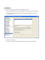
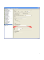
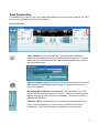
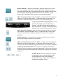
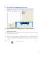
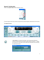
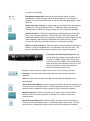
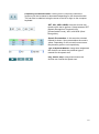
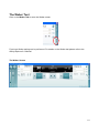
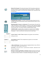
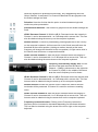
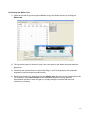
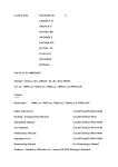
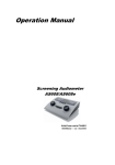
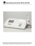
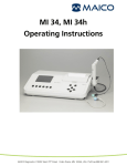
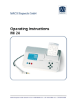
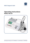
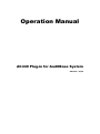
Operation Manual
AC440 Plug-in for AuditBase System
83015301 - 05/09
AC440 Plug-in for AuditBase
System
Contents
Introduction .................................................................................................................................................. 1
Installation .................................................................................................................................................... 2
Starting AC440 Plug-in .............................................................................................................................. 4
Tone Audiometry......................................................................................................................................... 5
The Tone Screen .................................................................................................................................... 5
Performing Tone Audiometry ................................................................................................................ 8
Speech Audiometry .................................................................................................................................... 9
The Speech Screen ................................................................................................................................ 9
Performing Speech Audiometry .......................................................................................................... 13
The Weber Test ........................................................................................................................................ 14
The Weber Screen................................................................................................................................ 14
Performing the Weber Test ................................................................................................................. 17
Auto Save Settings ................................................................................................................................... 18
PC Shortcuts.............................................................................................................................................. 17
Introduction
AuditBase System (AB) database has a diverse user group in the hospital, covering tasks such as
patient registration, invoicing, service and different hearing assessments based on measurements
from audiometers and tympanometers.
This user manual describes the use of AB together with the AC440 Plug-in made for the
Interacoustics AC440 audiometry module.
The AuditBase AC440 Plug-in gives a condensed access to the AC440 audiometer module and
accommodates for the air-bone-speech (SRT, WR and WR in noise) process with or without
masking, depending on the character of the hearing loss.
The application appears as a control panel on top of the AB application where the user controls the
instrument and the result of the measurement is simultaneously shown on the AB Audiogram. This
makes it possible for clinicians to record audiograms very fast and efficiently and get an overview
of the hearing impairment.
For in depth information regarding audiometry using the Affinity2.0/Equinox2.0 please refer to the
Affinity2.0/Equinox2.0 User Manual. Read more at www.interacoustics.com
1
Installation
To install the AC440 Plug-in, please follow the following four steps:
1) Insert the installation CD and run the installation file (if it does not start automatically)
2) Start AuditBase Administration and add a new audiometer application as shown on
screenshot below:
2
3
3) Press the "Test button"
4) Choose the new audiometer application path as shown on the screenshot below:
2
4
3
Starting AC440 Plug-in
Open and navigate AuditBase as described in the AuditBase User Manual.
Start AC440 Plug-in when selected as preferred audiometer
a. Select Measurement in the top tool bar
b. Choose AB Audiogram
c. Click the Measure button and the AC440 Plug-in will open
4
Tone Audiometry
The AC440 Plug-in opens in the Tone screen and enables the clinician is able to perform air, bone
and free field audiometry with or without masking.
The Tone Screen
Talk Forward: This button will activate Talk Forward that enables the
clinician to talk to the client through the talk forward microphone. To adjust
the sound level of the signal use the slider bars that appear when pressing
the talk forward button:-
Extended Range +20 dB: This button extends the testing range and can be
activated when the threshold search reaches 50 dB below the maximum
level of the headset.
Monitoring (M) of Channel 1 or Channel 2: The check boxes (Ch1 and
Ch2) enable the clinician to monitor Channel 1, Channel 2 or both Channels
together through an external monitor loudspeaker. The monitor intensity is
adjusted with the slider.
Talk Back (TB): If a microphone is connected to the Talk Back input the
clinician has the opportunity to listen to the client through an external
loudspeaker – when such has been connected to the monitor input
5
Output Channel 1: This dropdown provides the option to select output for
Ch1 - pure tone testing for both ears (Right and Left), bone conduction
testing for both ears (Bone R and Bone L), free field testing (FF1 and FF2),
and insert phone testing (Insert Right and Insert Left) .
Input Channel 1: The dropdown provides the option to select Tone
1 dB and 5 dB steps: This button allows for toggling between using 1 dB
and 5 dB intensity steps during the tone audiometry.
Manual or Reverse presentation in Channel 1: Here the clinician has the
option to choose Man (manual) and thereby present the signal to the client
only when the Stimuli Channel 1 is activated. Choosing Rev (reverse) will
cause the signal to be presented continuously, only disappearing when the
Stimuli Channel 1 is activated.
Pulsation: Here the clinician has the option to select between single and
continuous pulse presentation
Output Channel 2: This dropdown provides the option to select output for
Ch2 - pure tone testing for both ears (Right and Left), masking using an
insert phone (Insert Mask), free field testing (FF1 and FF2), and insert phone
testing (Insert Right and Insert Left). The Channel 2 can also be set to be
Off if masking is unnecessary.
Input Channel 2: This dropdown provides the option to select Tone, NB
(Narrow Band Noise) and WN (White Noise) as input for Channel 2.
Synchrony: This button will lock / synchronize the Channel 2 attenuator to
the Channel 1 attenuator.
Manual or Reverse presentation in Channel 2: Here the clinician has the
option to choose Man and thereby present the signal to the client only when
the Stimuli Channel 2 is activated. Choosing Rev will cause the signal to be
presented continuously, only disappearing when the Stimuli Channel 2 is
activated
Simultaneous/Alternate: Here the clinician has the option to select
presentation in both channels Sim by locking Channel 1 and Channel 2
together or to have the presentation in the two channels alternating to each
other Alt.
dB HL Decrease Channel 1: With the dB HL Decrease button the intensity
in Channel 1 can be decreased with 1 or 5 dB steps with a mouse click. This
can also be obtained using the arrow up on the computer keyboard
6
Stimuli Channel 1: Stimuli is presented by pressing space bar or left Ctrl
key on the computer keyboard. A left mouse click in the Stimuli area will
store the threshold at the current position (clicking at another intensity at the
same frequency will change the threshold to the new position). A right
mouse click in the Stimuli area will store a no response threshold.
dB HL Increase Channel 1: With the dB HL Increase button the intensity in
Channel 1 can be increased with 1 or 5 dB steps with a mouse click. This
can also be obtained sing the arrow down on the computer keyboard.
Frequency and Intensity display area: On the
left side of the black area the dB value for
Channel 1 (30 dB) is shown and on the right
side for Channel 2. (15 dB). In the middle of the
black area the current frequency level is shown.
dB HL Decrease Channel 2: With the dB HL Decrease button the intensity
and Channel 2 can be decreased with 1 or 5 dB steps with a mouse click.
This can however also be obtained using the arrow up on the computer
keyboard.
Stimuli Channel 2: The noise will be muted when the mouse is over the
Stimuli area or when right Ctrl key is pressed.
dB HL Increase Channel 2: With the dB HL Increase button the intensity in
Channel 2 can be increased with 1 or 5 dB steps with a mouse click. This
can however also be obtained using the arrow up on the computer keyboard.
Frequency increase/decrease: Clicking on the Frequency buttons the
frequency will be increased or decreased depending on the chosen direction.
This can also be obtained using the arrow to the left or right on the computer
keyboard.
HL, MCL & UCL: Here HL (Hearing Level) can
be selected to do a normal audiometry, MCL
can be selected in order to test the Most
Comfortable Levels, or UCL can be chosen to
test the Uncomfortable Levels
7
Performing Tone Audiometry
1) Open AC440 Plug-in through AuditBase (described above).
2) Select the input and output for Channel 1 using the corresponding dropdowns.
Using the Channel 2 input and output dropdowns the clinician can decide whether or not
masking is to be employed.
3) Use the arrow buttons on in the AC440 Plug-in, PC keyboard or the dedicated keyboard to
set the frequency and intensity.
4) Present the stimulus by touching the Stimuli area with the mouse, pressing S on the PC
keyboard, or the touch switch on the dedicated keyboard. During stimulus presentation
the Stimuli area will light up, visually letting the clinician no when sound is coming out of the
headphones.
5) If having to do with a more severe hearing loss the clinician may want to press the
Extended
Range +20 dB button
8
Speech Audiometry
Click on the Speech Tab to enter the speech screen:
From the speech screen the clinician can present the preferred speech material and score the test.
The Speech Screen
Talk Forward: This button will activate Talk Forward that enables the
clinician to talk to the client through the talk forward microphone. To adjust
the sound level of the signal use the slider bars that appear when pressing
the talk forward button
:
9
Extended Range +20 dB: This button extends the testing range and can
be activated when the threshold search reaches 50 dB below the maximum
level of the headset
Monitoring (M) of Channel 1 or Channel 2: The check boxes (Ch1 and
Ch2) enable the clinician to monitor Channel 1, Channel 2 or both
Channels together through an external monitor loudspeaker. The monitor
intensity is adjusted with the slider.
Talk Back (TB): If a microphone is connected to the Talk Back input the
clinician has the opportunity to listen to the client through an external
loudspeaker – when such has been connected to the monitor input.
Output Channel 1: This dropdown provides the option to select speech
testing output for both ears (Right and Left), bone conduction testing for
both ears (Bone Right and Bone Left), free field testing (FF1 and FF2), and
if using insert phones (Insert Right and Insert Left) as output for Channel 1.
Input Channel 1: The dropdown provides the option to select microphone,
CD player or Wave files (Mic1, Mic2, CD1, CD2, or Wave file) as input for
Channel 1.
1 dB and 5 dB steps: This button allows for toggling between using 1 dB
and 5 dB intensity steps during the speech audiometry.
Pulsation: Here the clinician has the option to select between Single Pulse
and Multi Pulse presentation.
Manual or Reverse presentation in Channel 1: Here the clinician has the
option to choose Man and thereby present the signal to the client only when
the stimuli/speech signal of Channel 1 is activated. Choosing Rev will cause
the signal to be presented continuously, only disappearing when the
stimuli/speech signal of Channel 1 is activated
Output Channel 2: This dropdown provides the option to select speech
testing output for both ears (Right and Left), Insert mask for masking via an
insert phone, free field testing (FF1 and FF2), and if using insert phones
(Insert Right and Insert Left) as output for Channel 2. This channel can also
be set to Off if masking or binaural stimulation is not wanted.
Input Channel 2: The dropdown provides the option to select microphone
(Mic1 and Mic2), Insert mask for masking via an insert phone, CD material
(CD1 and CD2), White Noise (WN), Speech Noise (SN), and Wave files as
input for Channel 2.
Manual or Reverse presentation in Channel 2: Here the clinician has the
option to choose Man and thereby present the signal to the client only when
the stimuli/speech signal of Channel 2 is activated. Choosing Rev will cause
the signal to be presented continuously, only disappearing when the Stimuli
10
Channel 2 is activated.
Simultaneous/Alternate: Here the clinician has the option to select
presentation in both channels Sim by locking Channel 1 and Channel 2
together or to have the presentation in the two channels alternating to each
other Alt.
dB HL Decrease Channel 1: With the dB HL Decrease button the intensity
in Channel 1 can be decreased with 1 or 5 dB steps with a mouse click.
This can also be obtained using the arrow up on the computer keyboard
Stimuli Channel 1: Stimuli is presented by pressing space bar or left Ctrl
key on the computer keyboard. A left mouse click in the Stimuli area will
store the threshold at the current position (clicking at another intensity at the
same frequency will change the threshold to the new position). A right
mouse click in the Stimuli area will store a no response threshold.
dB HL Increase Channel 1: With the dB HL Increase button the intensity in
Channel 1 can be increased with 1 or 5 dB steps with a mouse click. This
can also be obtained sing the arrow down on the computer keyboard.
F
Frequency and Intensity display area: On
the left side of the black area the dB value for
Channel 1 (30dB) is shown and on the right
side for Channel 2.(15dB). In the middle of the
black area the current Speech Score in % and
the Word Counter monitors the number of
words presented during the test.
Correct: A mouse click on this button will store the word as correctly repeated.
Incorrect: A mouse click on this button will store the word as incorrectly
repeated.
Store: A mouse click on this button will store the speech threshold in the
speech graph.
dB HL Decrease Channel 2: With the dB HL Decrease button the intensity and
Channel 2 can be decreased with 1 or 5 dB steps with a mouse click. This can
however also be obtained using the arrow up on the computer keyboard
Stimuli Channel 2: When the mouse cursor is above the Stimuli area the
selected stimulus will be presented. If Channel 2 is used for continuous
masking noise.
dB HL Increase Channel 2: With the dB HL Increase button the intensity in
Channel 2 can be increased with 1 or 5 dB steps with a mouse click. This can
however also be obtained using the arrow down on the computer keyboard
11
Frequency increase/decrease: Clicking on the Frequency buttons the
frequency will be increased or decreased depending on the chosen direction.
This can also be obtained using the arrow to the left or right on the computer
keyboard.
SRT, UCL, WR1 & WR2: Here the clinician can
choose which test to perform. Select between SRT
(Speech Recognition Threshold) UCL
(Uncomfortable Level), WR1, and WR2 (Word
Recognition).
Speech Presentation: In this area the selected
material is shown. Upon presentation the word is
yellow. Depending on the correct/incorrect score
they become green or red respectively.
Type of Speech Material: Using these dropdowns
the clinician can select the preferred type of
material for the speech test.
Play, Pause, Stop: Using these buttons the
clinician can control the speech test.
12
Performing Speech Audiometry
1) Open AC440 Plug-in through AuditBase and go to the Speech screen by clicking the
Speech tab.
2) Select the input and output for Channel 1 using the corresponding dropdowns.
3) Using the Channel 2 input and output dropdowns the clinician can decide whether or not
masking is to be employed.
4) Select the desired Speech material using the dropdowns
5) Set the input level using the arrow buttons in the AC440 Plug-in, PC keyboard or dedicated
keyboard.
6) Press Play
7) Score the test using the scoring buttons to score and store the speech test.
8) If having to do with a more severe hearing loss the clinician may want to press the
Extended
Range +20 dB button
13
The Weber Test
Click on the Weber Tab to enter the Weber screen.
From here Weber testing can be performed. For details on the Weber test please refer to the
Affinity/Equinox 2.0 Manual
The Weber Screen
14
Enable Talk Forward: This button will activate Talk Forward that enables the
clinician to talk to the client through the talk forward microphone To adjust the
sound level of the signal use the slider bars that appear when pressing the talk
forward button
Extended Range +20 dB: This button extends the testing range and can be
activated when the threshold search reaches 50 dB below the maximum level
of the headset.
Monitoring (M) of Channel 1 or Channel 2: The check boxes (Ch1 and Ch2)
enable the clinician to monitor Channel 1, Channel 2 or both Channels together
through an external monitor loudspeaker if a loudspeaker has been connected
to the monitor input. The monitor intensity is adjusted with the slider.
Talk Back (TB): If equipped with a microphone connected to the Talk Back
input the clinician has the opportunity listen to the client through an external
loudspeaker – when such has been connected to the monitor input.
Output Channel 1 and 2: These dropdowns are grayed out as the Weber
settings are fixed.
Input Channel 1 and 2: These dropdowns are grayed out as the Weber
settings are fixed.
1 dB and 5 dB steps: This button allows for toggling between using 1 dB and
5 dB intensity steps during the Weber test.
Synchrony: This button will lock / synchronize the Channel 1 attenuator to the
Channel 2 attenuator.
Manual or Reverse presentation in Channel 1 and 2: Here the clinician has
the option to choose Man (manual) and thereby present the signal to the client
only when the Stimuli Channel 1 is activated. Choosing Rev (reverse) will
15
cause the signal to be presented continuously, only disappearing when the
Stimuli Channel 1is activated. For Channel 2 Man and Rev are grayed out as
the Weber settings are fixed.
Pulsation: Here the clinician has the option to select between single and
continuous pulse presentation
Simultaneous/Alternate: This function is grayed out as the Weber settings are
fixed.
dB HL Decrease Channel 1: With the dB HL Decrease button the intensity in
Channel 1 can be decreased with 1 or 5 dB steps with a mouse click. This can
also be obtained using the arrow up on the computer keyboard
Stimuli Channel 1: Stimuli is presented by pressing space bar or left Ctrl key
on the computer keyboard. A left mouse click in the Stimuli area will store the
threshold at the current position (clicking at another intensity at the same
frequency will change the threshold to the new position). A right mouse click in
the Stimuli area will store a no response threshold.
dB HL Increase Channel 1: With the dB HL Increase button the intensity in
Channel 1 can be increased with 1 or 5 dB steps with a mouse click. This can
also be obtained using the arrow down on the computer keyboard.
Frequency and Intensity display area: On the
left side of the black area the dB value for
Channel 1 (30dB) is shown and on the right side
for Channel 2.(15dB). In the middle of the black
area the current frequency level is shown.
dB HL Decrease Channel 2: With the dB HL Decrease button the intensity and
Channel 2 can be decreased with 1 or 5 dB steps with a mouse click. This can
however also be obtained using the arrow up on the computer keyboard
Stimuli Channel 2: When the mouse cursor is above the Stimuli area the
tone/noise will be presented. If Channel 2 is used for continuous masking
noise.
dB HL Increase Channel 2: With the dB HL Increase button the intensity in
Channel 2 can be increased with 1 or 5 dB steps with a mouse click. This can
however also be obtained using the arrow down on the computer keyboard.
Frequency increase/decrease: Clicking on the Frequency buttons the
frequency will be increased or decreased depending on the chosen direction.
This can also be obtained using the arrow to the left or right on the computer
keyboard.
16
Performing the Weber Test
1) Open the AC440 Plug-in through AuditBase and go the Weber screen by clicking the
Weber tab.
2) The input and output for channel1 and 2 are not preset for the Weber test and therefore
grayed out
3) Use either the arrow buttons on the AC440 Plug-in, the PC keyboard or the dedicated
keyboard to set the frequency and intensity
4) Present the stimulus by either touching the Stimuli area with the mouse, pressing S on the
PC keyboard, or the touch switch on the dedicated keyboard. During stimulus
presentation the Stimuli area will light up, visually letting the clinician that the bone
conductor is vibrating.
17
Auto Save Settings
When the AC440 Plug-in is closed or another tab (tone, speech, Weber) is selected the the
transducers (input/output selection), presentation, pulsation and sim/alt settings automatically will
be saved in the XML file located under the application XML file under:
C:\Documents and Settings\All Users\Application Data\Interacoustics\ IA_ABAC440 Plug-in.xml
This XML file is hidden in Windows by default – to view it enable Show Hidden Files and Folders.
We do not recommend manually changing this XML file. However, experience super user and
system administrators may want to change some default settings in the Common section of the
XML file.
Warning: If a setting is typed in a wrong format (that cannot be read by the AC440 Plug-in) the
XML file will automatically be overwritten by the default settings (and the old setting will be lost).
The following settings can be changed in the Common area:
SinglePulseLength
value between 200 -> 5000 (ms)
:
MultiPulseLength
value between 200 -> 5000 (ms)
:
DefaultIntensityWhenChangingOutput
MinusTen
MinusFive
Zero
Five
Ten
Fifteen
Twenty
TwentyFive
Thirty
ThirtyFive
Fourty
FourtyFive
Fifty
Off
:
DefaultIntensityWhenChangingTest
MinusTen
MinusFive
Zero
Five
Ten
Fifteen
Twenty
TwentyFive
Thirty
ThirtyFive
Fourty
FourtyFive
Fifty
:
18
Off
MonitorLevel
value between -10 -> 30
:
TalkForwardLevel
value between
:
-10 -> 30
TalkForwardIntenity
value between 0 -> 120 (SPL)
:
TalkbackLevel
value between 0 -> 100 (SPL)
:
IntensityDecreseFrequencySteps
Off
Five
Ten
Fifteen
Twenty
TwentyFive
Thirty
ThirtyFive
Fourty
:
IgnoreMouseOverTouchSwitch
True
False
:
Ch2OppositeCh1Output
True
False
:
19
PC Shortcuts
Function
Hotkey
Test
Tone Test
F5
Speech, Weber
Speech Test
F7
Tone, Weber
Weber Test
F8
Tone, Speech
Toggle TF
Shift+F1
Tone, Speech, Weber
Toggle TB
Shift+F2
Tone, Speech, Weber
Toggle Extended Range
Shift+F3
Tone, Speech
Toggle Monitor for Ch1
Shift+F4
Tone, Speech, Weber
Toggle Monitor for Ch2
Shift+F5
Tone, Speech, Weber
Iterate Output Ch1
1
Tone, Speech
Iterate Input Ch1
2
Tone, Speech
Iterate Output Ch2
3
Tone, Speech
Iterate Input Ch2
4
Tone, Speech
Manual Ch1
5
Tone, Speech, Weber
Reverse Ch1
6
Tone, Speech, Weber
Manual Ch2
7
Tone, Speech
Reverse Ch2
8
Tone, Speech
Synchronize Ch2
9
Tone, Speech
Alternate Ch2
0
Tone, Speech
Puls
Alt+8
Tone, Speech, Weber
Multi puls
Alt+9
Tone, Speech, Weber
Continuous
Alt+0
Tone, Speech, Weber
Toggle Synchrone
Y
Tone, Speech, Weber
Right
R
Tone, Speech
Left
L
Tone, Speech
Freq. up
Right
Tone, Weber
Freq. down
Left
Tone, Weber
dB. up Ch1
down
Tone, Speech, Weber
dB. down Ch1
up
Tone, Speech
dB. up Ch2
Page down
Tone, Speech
dB. down Ch2
Page up
Tone, Speech
Store Heard
S
Tone, Speech
17
Store Not Heard
N
Tone
Reset
Shift-R
Speech
Incorrect
Right
Speech
Correct
Left
Speech
Toggle left meas. type
Z
Tone, Speech
Toggle right meas. type
X
Tone, Speech
Interrupter Ch1
Left cont| space
Tone, Speech, Weber
Interrupter Ch2
Right cont
Tone, Speech, Weber
18
Return Report – Form 001
Opr. dato:
Opr. dato:
2008-10-03
2008-10-03
Return
Report – Form 001 af:
af:
EC Rev. dato:
af:
EC
Rev. dato:
af:
HNI
HNI
Rev. nr.:
Rev. nr.:
4
4
Address
Drejervaenget 8
5610 Assens
Denmark
Company:
Address:
Phone
(+45) 63713555
Fax
(+45) 63713522
Phone:
E-mail
[email protected]
Fax or e-mail:
Contact person:
Date :
Following item is reported to be:
returned to INTERACOUSTICS for:
repair,
exchange,
other:
defective as described below with request of assistance
repaired locally as described below
showing general problems as described below
Item:
Type:
Quantity:
Serial No.:
Supplied by:
Included parts:
Important! - Accessories used together with the item must be included if
returned (e.g. external power supply, headsets, transducers and couplers).
Description of problem or the performed local repair:
Returned according to agreement with:
Date :
Interacoustics,
Other :
Person :
Please provide e-mail address or fax No. to whom Interacoustics may
confirm reception of the returned goods:
The above mentioned item is reported to be dangerous to patient or user
1
In order to ensure instant and effective treatment of returned goods, it is important that this form is filled in and
placed together with the item.
Please note that the goods must be carefully packed, preferably in original packing, in order to avoid damage
during transport. (Packing material may be ordered from Interacoustics)
1
EC Medical Device Directive rules require immediate report to be sent, if the device by malfunction
deterioration of performance or characteristics and/or by inadequacy in labelling or instructions for use, has
caused or could have caused death or serious deterioration of health to patient or user.
Page 1 of 1
19