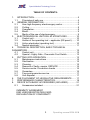
1
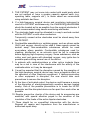
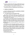
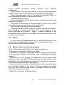
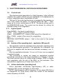
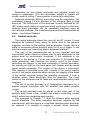
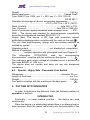
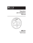
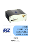
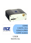
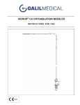
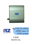
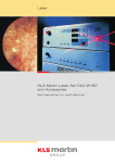
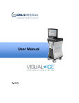
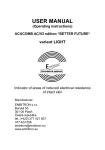
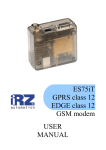
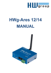
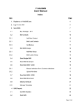
Special Medical Technology Co.Ltd.
HF/RF Electrosurgery Unit
SMT ESU 60 M (MONO)
Operating Manual
Special Medical Technology Co.Ltd.
TABLE OF CONTENTS:
1.
INTRODUCTION ...................................................................... 4
1.1.
Principles of safe use ....................................................... 4
2.
GENERAL INFORMATION....................................................... 6
2.1.
How high-frequency electrosurgery works......................... 6
2.2.
Cutting ............................................................................. 8
2.3.
Coagulation...................................................................... 8
2.4.
Blend................................................................................ 9
2.5.
Merits of the use of electrosurgery.................................... 9
3.
ELECTROSURGICAL UNIT ESU 60 M FEATURES............... 10
3.1.
Control unit..................................................................... 10
3.2.
Holder of the operating tool – applicator (ES pencil) ....... 10
3.3.
Active electrodes (operating tool) ................................... 10
3.4.
Neutral electrode............................................................ 11
4.
TECHNICAL DESCRIPTION, BASIC TECHNICAL
PARAMETERS ............................................................................... 12
4.1.
Control unit..................................................................... 12
4.2.
Special - Highly Safe - Pneumatic Foot Switch............... 13
5.
PUTTING INTO OPERATION ................................................ 13
5.1.
Maintenance instructions................................................ 15
5.2.
Sterilisation .................................................................... 15
5.3.
Cleaning......................................................................... 15
5.4.
Removal of faults, repairs, SERVICE ............................. 16
5.5.
Service centre: Preventive checks ................................. 16
5.6.
Guarantee ...................................................................... 16
5.7.
Free post-guarantee service........................................... 17
5.8.
Unit disposal................................................................... 17
6.
THE FULFILMENT OF LEGISLATIVE REQUIREMENTS....... 17
7.
PERFORMANCE CHARACTERISTICS.................................. 18
8.
DEVICE WITH BASIC ACCESSORIES (INCLUDED)............. 21
8.1.
Accessories included: ..................................................... 21
INDEMNITY AGREEMENT
END USER REGISTRATION CARD
DECLARATION OF CONFORMITY
3
Operating manual ESU 60 M
Special Medical Technology Co.Ltd.
Manufacturer:
Special Medical Technology, Co. Ltd.
Papírenská 114/5
160 00 Prague 6
Czech Republic
Phone: +420 233 320 201, Fax: +420 224 318 011
E-mail: [email protected], [email protected]
Internet: www.smt-praha.com
Device classification class: .......................................................... II b
Device service life: ............................................................... 7 years
1. INTRODUCTION
In view of the continuously ongoing development, some of the
device’s characteristics and technical data may be changed without
prior warning.
No part of this document may be photographed, reproduced or
translated into another language without the written permission of the
manufacturer.
In the event that technical assistance is required, contact the
supplier.
It is very important that this manual is kept for future consultation.
1.1.
Principles of safe use
Operation of all high-frequency (HF) or radio-frequency (RF)
surgical devices brings certain risks and specific rules need to be
observed to minimise these risks. In terms of transparency, we
provide a general outline of these rules here and many of these rules
are mentioned again further in the text.
These instructions were compiled for your safety and for the
safety of other persons therefore we request that you read them
carefully before installing and using the device:
1. An operator with a university medical degree is required to work
with the electrosurgical device (HF/RF generator).
2. If other than the accessories (cables and instruments) supplied by
the manufacturer are used, the manufacturer needs to be
consulted to prevent incompatibility, dangerous operation and
personal risk!
4
Special Medical Technology Co.Ltd.
3. THE PATIENT may not come into contact with metal parts which
are not earthed or have a greater capacity against earth (e.g.
operating table, supports etc.). In these cases we recommend
using antistatic bed linen.
4. If a high-frequency surgical device and monitoring instrument is
used on a PATIENT simultaneously, the monitoring electrodes
should be located as far as possible from the surgical electrodes. It
is not recommended using needle monitoring electrodes.
5. The electrode feeds must be allocated in a way to exclude contact
with the PATIENT or with other conductors.
Temporarily unused active electrodes must be stored away from
the PATIENT.
6. Combustible anaesthetics or oxidising gases, such as nitrous oxide
(N2O) and oxygen, should not be used if these agents cannot be
sucked away. Non-combustible substances should be used
everywhere where possible. Combustible substances used for
cleaning, disinfection or as solvents must be left to evaporate
before applying high-frequency surgery. Some substances, such as
cotton wool and gauze with absorbed oxygen, may ignite due to
possible sparks during normal use of the device.
7. In patients with cardiostimulators or other active implants there
may be a risk in view of the interference with the activity of the
cardiostimulator or it may be damaged.
8. It must be expected that the disruption caused by the operation of
the high-frequency surgical device may have a negative effect on
the operation of other electronic equipment. If telecommunication
or other equipment is disrupted, the user should take such
precautions to remove the disruption.
9. At the time of activated output, the device could become a source
of the disruption of electromagnetically sensitive devices located
nearby. One of the possible precautions is to locate the HF/RF
generator and the disrupted device as far apart from each other as
possible.
10. Regular preventive checks of the device and its accessories are
essential, with special attention payed to the condition of the
insulation of the feeds of the active bipolar electrodes.
11. There should be no unqualified intervention with the device.
Request all repairs and inspections from the manufacturer or
authorised repair shop.
5
Operating manual ESU 60 M
Special Medical Technology Co.Ltd.
12. In order to minimise risks arising from a possible power cut, we
recommend using the device in operating rooms with a backup
supply of electricity, and we recommend feeding the device from
an uninterruptable power supply (UPS) for outpatient use.
13. The device needs to be inspected by the manufacturer or
authorised service centre for safety reasons at least once a year.
2. GENERAL INFORMATION
In order to achieve the best results, it is important to understand
the basics of electrosurgery and so we recommend that you read the
following basic explanation carefully.
2.1.
How high-frequency electrosurgery works
The device’s electrode concentrates HF (RF) energy to the
required place. The HF (RF) current passes through the tissue
painlessly, without shock and the sole effect is creating heat inside the
tissue, moderate intensity of the current only in the place that comes
in contact with the active electrode.
The HF (RF) current, passing through the tissue, creates molecular
heat. Electrodes of various sizes are used in electrosurgery. In the
bipolar method energy is concentrated with very high intensity on both
working tips of the bipolar electrodes (usually the forceps). When this
is applied to the tissue, the HF (RF) current creates such intensive
molecular heat in each cell that it is possible to cut the tissue or
coagulate (according to the output option CUT or COAG or mix of
both - BLEND).
The main aim of good electrosurgical technique in general is to
remove undesired tissue, stop bleeding without carbonisation of the
surroundings, or to gain a precisely orientated and not destroyed
sample of tissue for biological analysis and diagnosis. Some operating
principles of electrosurgery need to be observed, to achieve a good
result. Choose the optimum parameters. Choose the right mode for
the chosen device. Remove all possible other conducting undesired
diverters, including conducting fluids (e.g. disinfectants), out of reach
of the electrodes and the patient.
The procedure may not be perfect if:
- Excessive power is used
- The power used is too small
- The moving through the tissue is too slow
6
Special Medical Technology Co.Ltd.
- The procedure is repeated in the same area too soon
Too small power results in the tissue fibres stick to the electrode and
cause problems during further work.
A somewhat greater power may cause slight dehydration of the
tissue surface at most without damaging it. If you choose the right
operating output and performance of the device, you will achieve the
desired result. It must be realised that the output CUT is without
modulation, and therefore will reach a higher tissue temperature (over
100 °C). Water inside the cell boils and the cell bursts – it is destroyed
for good. On the contrary, the output COAG has modulation – for the
purpose of reducing the max. temperature of the water inside the cell
(to 40-90 °C) and thereby coagulation (closing) the cell, not its
destruction.
The device also contains the output BLEND which can be used to
advantage where a combination of advantages is required of both
outputs with partial destruction of the tissue.
A characteristic odour arises during electrosurgical procedures,
which can be removed by central suction from the operated place. A
suction unit is available or designed for this, holding a suction hose as
close to the place of the procedure as possible. In the field of
gynaecology, or proctology a speculla with a connector for the suction
can be used during open surgery. It is constructed for this purpose. In
endoscopic methods complex suction of the cavity, moreover for
clearing the operating field, is available.
The manufacturer of this device also offers effective suction units
which eliminate this sole disadvantage of all electrosurgical devices.
How to operate:
Firmly attach the neutral electrode to the patient. Remove all
possible other conducting undesired diverters, including conducting
fluids (such as disinfectants), out of reach of the electrodes and the
patient. Move the device with the electrode continuously during the
procedure to prevent heat accumulating in some part of the tissue.
- Too great a performance results in tissue dehydration and when
moving the electrode in the tissue it is possible to observe sparks.
- Too low a performance results in tissue dehydration and tissue fibre,
stick to the electrode and cause problems with their removal.
- Somewhat greater performance may cause slight tissue surface
dehydration at most without damaging it with an adequate cutting
movement, whereas too low a performance prevents the electrode
from moving around the tissue.
7
Operating manual ESU 60 M
Special Medical Technology Co.Ltd.
OPERATING OUTPUTS OF DEVICE ESU 60 M
2.2.
Cutting
This is the separation of biological tissue with the passage of
HF/RF current of high intensity concentrated in the cutting parts of the
active electrode. When the HF/RF current is applied to the tissue with
the aid of the active electrode, it creates intensive molecular heat in
the cell which destroys the cell and separates the tissue.
The cutting effect is achieved by moving the tissue electrode and
gradual cell destruction one after another. The continuous movement
of the electrode prevents the lateral spread of heat in the tissue,
thereby limits destruction of the number of cells to a minimum.
The most appropriate current for cutting is fully balanced and
filtered HF (RF) current without any modulation. Such a current cuts
very smoothly.
The following rules will help the operator to achieve a good cut
however each user must follow his professional judgement as is
always the case in practice.
- Move the electrode continuously without stopping.
- Activate the electrode just before contact with the tissue.
- Keep the electrode clean.
If the output performance is selected correctly, then:
- The electrode moves without resistance.
- No changes occur in the colour of the cut surface.
- Fibres from the tissue should not remain on the electrode.
2.3.
Coagulation
This is hemostasis of small (blood) vessels of body tissue caused
by the passage of the HF/RF current with the effect of active, most
commonly spherical electrodes. If the current intensity is reduced and
a large-scale electrode is used for the purpose of dispersing the
energy over a greater area, this will cause the drying out of surface
cells without deeper penetration and the onset of coagulation. The
surface of such coagulated cells behaves like an insulating layer
which prevents the penetration of heat arising with the subsequent
application of the current to a greater depth.
The current which is normally used for coagulation is always
blended and modulated and the depth of modulation then depends on
the quality of tissue hemostasis. The deeper modulation of the HF/RF
8
Special Medical Technology Co.Ltd.
current causes somewhat rougher, however more effective
coagulation.
The following rules help the operator to achieve good coagulation
however every user must follow their own professional judgement:
Select the appropriate size of the spherical electrode (BALL) or
other appropriately shaped coagulating electrode.
Localise bleeding vessels.
Touch the bleeding vessels slightly before activating the electrode,
press the foot switch.
Terminate the activation of the electrode as soon as the tissue
goes pale to prevent unnecessary tissue destruction.
Keep the operating device sterile and clean.
Monopolar forceps, péan forceps or scissors can also be used for
the coagulation. In such a case both lines of instruments is one –
active electrode and another - bigger – passive electrode is the
neutral electrode attached to the patient (as close to the place of the
procedure as possible).
2.4.
Blend
In some cases it is advantageous to CUT and COAGULATE in one
intervention, by one operating instrument. For these cases is the
slection of the BLEND output suitable.
2.5.
Merits of the use of electrosurgery
Some of the basic merits of the use of electrosurgery are:
- Prevention or restriction of the loss of tissue.
- Prevention or restriction of bleeding makes it difficult for the doctor
to see into the operating field when using a traditional instrument
(scalpel).
- Prevention of bone damage. Provided that care is taken when
carrying out the procedure with the electrode, the bone tissue is not
affected by the electrosurgical procedure. The continuous movement
of the electrode prevents heat accumulation.
- Quick and positive healing of healthy tissue with good generation
and with little scarring of the tissue. The time required for healing
does not differ from the time during a procedure performed with a
traditional instrument (scalpel).
- Restriction of the pain of the procedure.
9
Operating manual ESU 60 M
Special Medical Technology Co.Ltd.
3. ELECTROSURGICAL UNIT ESU 60 M FEATURES
3.1.
Control unit
The electrosurgical generators is a high-frequency, highly efficient
oscillator the current of which may be modulated if it is appropriate for
cutting, coagulation and a combination of both.
The level of the output performance is managed by the operator so
that it fully meets his needs. It is optional within the “Min” – “Max”
range up to a max. performance of 60 W. The device allows work in
the MONOPOLAR mode. The current can be chosen for cutting, for
blended cutting or for coagulation.
3.1.1. Lights signals
Green MAINS – the device is switched on
Yellow CUT – output current for cutting
Green BLENDED CUT – output of the current for a blended cut
Blue COAG - output of the current for coagulation
Red ................................................................................................
NEUTRAL ELECTRODE (alarm) – fault in the circuit of the neutral
electrode
3.2.
Holder of the operating tool – applicator (ES pencil)
The applicator holds the selected active electrode (operating tool)
for the electrosurgical procedure. The applicator for monopolar use
(2.4 mm) is supplied with the device as the basic accessory, com. 2,
FIG 4.
Also the applicators diameter 1.6 mm or 0.8 mm can be supplied
as optional access.
This procedure is carried out based on specialised medical
procedures according to the recommendations in Chapter 2 above.
The most common use is for cutting using a scalpel, LOOP or needle
and coagulation with the aid of the BALL or flat electrode. (The
manufacturer supplies any of these tools.) See 3.3.
3.3.
Active electrodes (operating tool)
Active electrodes concentrate high-frequency (HF) or radiofrequency (RF) current and apply it to the tissue.
NOTE: High-frequency with a frequency of over about 200 KHz is
not dangerous for living tissue unlike the current of the standard
mains frequency of 50 Hz!
10
Special Medical Technology Co.Ltd.
Depending on their shape electrodes are intended mostly for
cutting or coagulation. Thin wire electrodes, straight or looped, are
usually used for cutting. Tissue excision is carried out using loops.
Spherical electrodes (BALLs) are mainly used for coagulation. The
normalised gripping 2.4 mm diameter of the electrode stem is used
above all. The cutting end of the electrode is partly sterilised by HF
(RF) energy which destroys organisms which could occur in this area.
However most electrodes can be repeatedly sterilised using all
conventional methods. The manufacturer recommends sterilisation by
steam – see further Chapters.
3.4.
Neutral electrode
The neutral electrode closes the circuit of the NF current. It must
therefore be fastened firmly along its entire area to the patient’s
organism, as close to the working field as possible. Usually this is a
metal or conducting silicon board of about 6x14 cm or bigger. It can
also be a single-use conducting plastic (dispersal) material.
This part of the electrosurgical set is very important and the
international safety directive requires that its safe attachment to the
patient must be continuously monitored. If this electrode is not
attached to the device or if even one conductor of the double feed
cable interrupted, and therefore the electric circuit is not closed,
controlling the integrity of the feed conductors of neutral electrodes,
the warning red light on the back panel (left) flashes and the sound
signal sounds repeatedly. The function of the device is interrupted.
This warning is activated even with a break in the control electric
circuit of the neutral electrode which controls the integrity of the feeds
to the neutral electrode during the operating procedure. If such a
situation arises, these electrodes must be inspected. The visual
control of the electrode and its feeds are recommended before each
operation.
The use of neutral electrode is of fundamental importance for a
precise surgical procedure with the smallest and safest possible
current.
The neutral electrode must be placed so that some part of the
patient’s body forms a firm, reliable and electric conducting contact
with it, without any separating pads (gauze).
The principles in Chapter 1.1 must be followed when applying
neutral electrode. The basic operating electrode supplied by the
manufacturer with this device is a multiuse stainless steel electrode.
As required it is possible to supply a neutral silicon electrode.
11
Operating manual ESU 60 M
Special Medical Technology Co.Ltd.
However when using the electrode it needs to undergo repeated
inspection to check its electric conductivity, at least once every 6
months because silicon electrodes lose their conductivity in time. The
service life of silicon neutral electrodes is limited to a period of 12
months. Once this period expires, the silicon electrode must be
replaced with a new one.
Simple and cheap neutral electrodes with conducting gel, usually
self-adhesive, are intended for single use. Feeds to these electrodes
are checked by the above described electric circuit and its interruption
is indicated, just as in previous types, visually and acoustically on the
control unit panel, with the current automatic interruption of the
device’s function. The use of single-use self-adhesive neutral
electrodes is a full alternative. Despite a neutral electrode, the current
circuit is closed so it must be reliably attached for conductivity! With a
bad connection a patient could be burnt in the place of the neutral
electrode, or even in a different place (e.g. there where an unwanted
conducting connection arises, e.g. conducting disinfectant which is
absorbed into the cushion under the patient!)
The neutral electrode set is insulated as its insulation complies with
type F which complies with mark F on the device. The neutral
electrode stainless steel is supplied with the device as its basic
accessories com. 3, FIG 4.
4. TECHNICAL DESCRIPTION, BASIC TECHNICAL
PARAMETERS
4.1.
Control unit
Feed voltage ........................................ 230V~/50Hz (or as ordered)
Maximum input:
Cut
Blended cut
Coagulation
85 VA
75 VA
75 VA
at impedance of
at impedance of
at impedance of
500 Ω
500 Ω
500 Ω
No load input .............................................................................5 VA
Working output (CUT-at impedance 500-1500 Ω) ………………60 W
Max. output (CUT-at impedance 850 Ω) ................................... 68 W
Working frequency (controlled by crystal) ........................460.85 kHz
Class II insulation ..............................................................symbol
Dimensions ........................................................ 260 x 160 x 80 mm
12
Special Medical Technology Co.Ltd.
Weight .................................................................................. 2.25 kg
Mains transformer ....................................................... Talema Plzeň
Type 52643; Prim. 230V, sec. 1 = 45V, sec. 2 = 16V; 100 VA;
EN 60 601-1
Operation and storage of device: surrounding temperature ...............
......................................................+10°C (+50°F) to + 40°C (104°F)
Relat. humidity....................................................... from 30% to 75%
Atm. Pressure ................................................. from 700 to 1060 kPa
Level of protection against unwanted water seepage cover ........IP21
EMC – The device was checked for electromagnetic compatibility
according to international standard EN 60 601-1-2.
Output data: The device is BF type with protection against
defibrillating discharge which complies with the mark on the unit
.
The unit uses high-frequency energy with non-ionising radiation as
marked by symbol.......................................................................
.
Operating output .................................. cut, blended cut, coagulation
Method of operation ..........................................................................
...................constant operation with interrupted load (see Chapter 5)
The
information
“ATTENTION,
read
the
accompanying
documentation” complies with the marking on the device............. !
The maximum peak output voltage of unloaded circuit is achieved in
the mode BLEND, of 1140 Všp-šp.
The device does not contain and does not use any dangerous
substances.
4.2.
Special - Highly Safe - Pneumatic Foot Switch
Dimensions............................................................. diameter 70 mm
Length of feed hose ............................................................. cca 3 m
Weight .................................................................................. 0.25 kg
Foot switch complies with this marking on the back panel ...........
5. PUTTING INTO OPERATION
In order to determine the technical limits the following method of
operation is defined:
INTERRUPTED.
Practically – in usual medical practice - the device can work
continuously.
Place the device in a stable place where there is no blazing heat or
direct sunrays. Slide the mains cable firstly into the back panel of the
13
Operating manual ESU 60 M
Special Medical Technology Co.Ltd.
control unit (com.2, FIG. 2), then connect to a properly installed
electric mains socket.
Slide the flexible tube of the foot pneumatic switch into the
opening on the back panel (com.1, FIG. 2).
Switch on the mains switch on the back of the panel (com.3, FIG.
2) – light warning signal (com.5, FIG. 1). Slide the instrument cable
into the relevant connection as seen in the figure of the front panel
(com. 2, FIG. 1). Select the operating output with the function switch
(com.7, FIG. 1). Set the preliminary value of the power with the
intensity regulator (com.3, FIG. 1).
Now the “Operating Process” may begin by pressing the foot
switch. The relevant light signal lights up to indicate that the
preselected operating output is activated (com.6, FIG. 1) while a
continuous acoustic signal sounds out.
7
6
2
®
T
BLEND
CO
AG
A
PP
PO
W
ER
CA
UT
IO
FIG. 1
LIC A T O
N
MI
N
EU
F
5
R
CU
TR
A L EL E C T R
4
LO A D
N
MA
X
E
OD
1
3
- Front control unit panel
Legend:
1. neutral electrode socket
2. active electrode socket
3. regulator of intensity (W)
4. red light signal indicating bad connection of neutral electrode
5. green signal indicating that the mains is switched on
6. function signal (operating outputs indicator)
7. function switch (operating outputs selector)
14
Special Medical Technology Co.Ltd.
4
O
O
N .:
.:
4
FIG. 2
MAIN S
220÷240V~
0Hz / /1105/17
05/17 VA
220÷240V~/ /50÷6
50÷60Hz
VA
Output:
W
kHz
Out put:60
75
W/ 460.85
/ 4 60.85
kHz
1014
EC285/
2006
922/
2010
I
0
1
2
3
- Back control unit panel
Legend:
1- pneumatic foot switch connector
2- mains cable socket
3- mains switch
4- production label
5.1.
Maintenance instructions
The high-frequency unit does not require any special maintenance
besides standard cleaning of all parts. Any repairs must be ordered
with the supplier, authorised repair shop or with the very
manufacturer.
5.2.
Sterilisation
An autoclave, formaldehyde or ethylene oxide can be used to
sterilise cables and operating instruments designed by the
manufacturer for sterilisation. Hot air at a temperature of 160 °C can
also be used to sterilise the actual reusable forceps. A preventive
visual inspection of the cables and forceps (or other instruments) is
required after each sterilisation.
5.3.
Cleaning
The surface of the control unit box can be wiped with damp gauze
containing standard detergent, however make sure the washing
solution does not get into any opening. The mains cable plug must be
removed from the socket (when being wiped). The operating tools and
the cable can be cleaned in a similar way as the control unit.
Moreover, the active (non-insulated) part of the operating instrument
15
Operating manual ESU 60 M
Special Medical Technology Co.Ltd.
must be well cleaned mechanically and adequately rinsed in running
water.
5.4.
Removal of faults, repairs, SERVICE
If the instrument does not work and the function light signal lights
up after the foot switch is pressed down and the continuous sound
signal is activated, check whether the forceps are correctly connected
and if the high-frequency current intensity is properly set.
In case the instrument is not responding after the unit is switched
on and the foot switch pressed down, the function control light is not lit
up and the signal does not sound even after carefully checking that all
the connectors are in place, the fault may be in the circuits of the
control unit. In such a case you need to contact your supplier, service
organisation or the manufacturer directly.
5.5.
Service centre: Preventive checks
Preventive checks need to be carried out as the law requires at
least once every 12 months, additional parts and the cables once
every 6 months. In case of sterilisation (in the above recommended
way) run a visual check of the instrument and any other additional part
with the cable after each sterilisation.
Preventive safety inspections at the manufacturer or the
authorised service centre must be carried out once a year. During
each inspection the HF (RF) output of the device must be measured
at each power degree and each operating output.
5.6.
Guarantee
The manufacturer provides a 24-month guarantee from the date of
sale for the correct and faultless function of the unit. During this
guarantee period the manufacturer will ensure free repair if the
product was not damaged by bad handling, an unprofessional
procedure or due to non-observance of the instructions contained in
this manual.
5.6.1. Instructions for guarantee repairs
Send the properly wrapped up unit and accessory – if possible in
its original packaging - (or transport in person) with the attached
certificate of guarantee and a description of the fault to the address of
the supplier or manufacturer, or upon a telephone agreement with the
manufacturer, to the address of the nearest relevant service
organisation.
16
Special Medical Technology Co.Ltd.
5.7.
Free post-guarantee service
Besides a guarantee, the manufacturer also provides an additional
two-year free service provided that the legal requirements of regular
technical inspections by the manufacturer are carried out. This service
does not apply to normal wear and tear, to damage from
unprofessional intervention, mechanical damage (e.g. the unit falling)
or to the accessories which are consumer material.
5.8.
Unit disposal
The ES unit must be disposed of in accordance with valid
legislative standards and regulations
. The manufacturer is
registered under the legislative requirements at the Ministry of
Environment under registration number 00794/05-ECZ and is obliged
to accept the unit for liquidation.
6. THE FULFILMENT OF LEGISLATIVE REQUIREMENTS
The conformity was reviewed with the product.
The manufacturer declares at its own responsibility exclusively that
the product fulfils basic requirements stated in Annex 1 of Regulations
of the Czech Government No. 336/2004 Coll. (93/42/EEC) in the
relevant valid readings.
For the review were used these harmonised standards in a valid
reading:
EN ISO 13485
EN 60601-1
EN 60601-1-2
EN 60601-2-2
The examination of the conformity was carried out in participation
of the Authoritative person – Notified Body No. 1014.
The Manufacturer issued a Declaration of Conformity on this
matter.
17
Operating manual ESU 60 M
Special Medical Technology Co.Ltd.
7. PERFORMANCE CHARACTERISTICS
FIG. 3
- Situating power setting values
Maximum performance values are achieved at an impedance of
850 Ω.
18
Special Medical Technology Co.Ltd.
70
60
Rz
Power [W]
50
50
40
100
200
500
850
1000
2000
30
20
10
0
Min
1
2
3
4
5
Max
Setting
Graph 1
- Cut
60
50
Rz
Power [W]
40
50
100
200
500
850
1000
2000
30
20
10
0
Min
1
2
3
4
5
Max
Setting
Graph 2
- Blend
19
Operating manual ESU 60 M
Special Medical Technology Co.Ltd.
60
50
Rz
Power [W]
40
50
100
200
500
850
1000
2000
30
20
10
0
Min
1
2
3
4
5
Max
Setting
Graph 3
- Coagulation
Power (maximal setting) [W]
70
60
50
40
Cut
Blend
30
Coag
20
10
0
0
500
1000
1500
2000
Rz[Ω]
Graph 4
- Dependence of input power on load
20
Special Medical Technology Co.Ltd.
8. DEVICE WITH BASIC ACCESSORIES (INCLUDED)
FIG. 4
8.1.
123456-
Accessories included:
control unit
instrument with cable
neutral electrode (flat or circle)
foot switch
line cord
instrument holder
user manual with certificate of warranty, declaration of conformity
and registration card
packing
21
Operating manual ESU 60 M
INDEMNITY AGREEMENT
Product:
ELECTROCAUTER - ELECTROSURGERY UNIT
TYPE:
SMT ESU 60 M
Serial number:
Date of sale:
Stamp and signature of expedition:
Guarantee Conditions:
a) At observing Operating Instructions the manufacturer guarantees
that the product shall have characteristics assessed by the relevant
technical conditions and standards for the duration of 24 months from
the date of sale.
b) In case of failure in function of the product, not caused by the end
user or by an inevitable event within the guarantee period, the product
will be repaired free of charge.
c) The free of charge repair within the guarantee period will be done
after the presentation of the Indemnity Agreement by an accredited
service or by manufacturer.
d) The guarantee period shall be extended for a term of the guarantee
repair.
e) The Indemnity Agreement is at the same time “The Certificate of
the Quality and Completeness of the Product”.
RECORDS OF REPAIRS
Date of reception:
Description of malfunction:
Completion date:
Signature and stamp of the service:
Date of reception:
Description of malfunction:
Completion date:
Signature and stamp of the service:
Date of reception:
Description of malfunction:
Completion date:
Signature and stamp of the service:
Date of reception:
Description of malfunction:
Completion date:
Signature and stamp of the service:
END USER REGISTRATION CARD
PRODUCT: ELECTROSURGERY SYSTEM SMT
TYPE: SMT ESU 60 M
Serial number:
Sales clerk:
User:
Name:
Organization:
Address:
Phone:
Fax:
Herewith I confirm that I have got acquainted with the Operating
Instructions and with the Guarantee Conditions and I will observe
them.
Date:
Signature:
Dear customers,
Will you tear this registration card out and forward it to the
address:
Special Medical Technology Ltd., Papirenska 114/5, 160 00, Prague 6, Czech Republic
The objective of this registration is, partly, to improve the quality of services our firm
offers to its customers, and, partly, to observe strict requirements of standards ISO
9001, ISO 13485 and EEC 93/42 our firm conforms and the user of medical
technology must be acquainted with.
Thank You
Special Medical Technology Co. Ltd.
Papirenska 114 / 5
160 00 Prague 6, Czech Republic
Tel.: + 420 233 320 201
Fax: + 420 224 318 011
[email protected]
N 00146.01
www.smt-praha.com
The last revision and issue of this Operating Instructions 10/15/2012