1
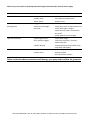
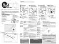
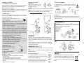
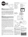
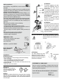
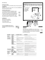
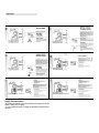
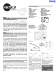
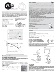
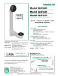
 OPERATIONS AND MAINTENANCE INSTRUCTIONS RESIDENTIAL SERIES RB203‐F, RB204‐F, RB303.5‐F, RB207‐P ***Do not accept any package that is damaged or appears to be damaged. Contact Aqua Pro Pump Systems immediately. *** Carefully follow the instructions below to obtain the best performance and a long service life from your pump. Contact Aqua Pro Pump Systems technical support if you have any problem. OPERATING CONDITIONS: These pumps have been designed to pump neutral clean liquids in which no abrasive solids are suspended at temperatures of no more than 176°F (140°F for electric pumps with plastic impellers or diffusers) continuous operation. INSTALLATION: The installation should be conducted by specialized professional and/or technical persons. The pumps must be installed in a dry well‐ventilated place with an ambient temperature of no more than 104°F (Fig A). Pumps used for cleaning and swimming pool maintenance purposes should not be used when there are people in the pool and must be operated through a ground fault interrupt (GFI) with a rated residual operating current not exceeding 30mA. Pumps for outdoor fountains, garden ponds and similar places must be supplied though a ground fault interrupt (GFI) with a rated residual operating current not exceeding 30mA. Fix the pump in place on a solid flat surface using suitable bolts to avoid vibration. The pump must be installed in horizontal position to ensure that the bearings operate correctly. The diameter of the discharge pipe from the pump must be smaller than that of the suction pipe to the pump. If the suction pipe height exceeds 13’, use a pipe with a larger diameter. The diameter of the suction pipe must be chosen to suit the flow rate and pressure required at the takeoff points. The suction pipe must be slightly angled up towards the pump suction to avoid the formation of air locks. Make sure that the suction pipe is completely airtight and submerged in the water by at least 1.5’ to avoid the formation of vortexes. Always fit a foot valve at the end of the intake pipe. It is advisable to fit a non‐return valve between the delivery mouth and flow rate adjustment gate valve to avoid dangerous water hammering in the event of the pump suddenly stops. This measure is necessary if the suction pipe is over 65’. The pipes must always be fitted using the related brackets to avoid transmitting stress to the pump body. Take care not to damage any part by over tightening the pipes when fitting them. ELECTRICAL CONNECTIONS: The installer is responsible for making the electrical connections to the mains supply in compliance with the local codes. ‐The electric pump is not equipped with a supply cable; the installer must cover the three wires of the supply cable inside the terminal box with three small tubes of the isolation material with the following characteristics: Working temperature not inferior to 194°F and electric strength more than 2,5kV. ‐note that most local regulations demand that fixed installations incorporate a cut out device ensuring disconnection from the main power supply; OFFICE & WAREHOUSE: 1615 W. 10th STREET ANTIOCH, CA 94509 • PH 925‐754‐5686 • FAX 925‐754‐5691 ‐make sure that the specifications on the pump rating plate and the rated line values are the same. ‐connect the pump to an effective earth circuit and then connect the phases following the diagram on the terminal block cover or rating plate. ‐single‐phase motors are protected against overloads using a thermal device (overload cutout) fitted in the winding. Users are responsible for fitting a suitable protection device for three‐phase motors; ‐check that three‐phase pumps rotate clockwise when looking at the pump from the motor (rear) side, swapping over two of the phase connections if the motor turns counterclockwise. For pumps meant to be used in swimming pools and for outdoor use the supply cord should be properly sized depending on the motor amperage draw and length of the run. Please contact APPS for assistance if you think you have an application that fits this description. If a pump is not equipped with a supply cord and a plug, the power supply network should include a cut‐off device or system having a contact separation of at least 3mm in all pools. If a pump is provided with a supply cord and a plug, the pump must be positioned so that the plug is accessible. It’s advisable to install a residual current device (RCD) with a rated residual operating current not exceeding 30 mA. PRIMING: Fill the pump completely with clean water before energizing. The water should be poured in through the priming plug of the volute (housing) of the pump. When you have completed the operation, screw the plug back in again and start the pump. The pump should be primed again whenever it has not been used for a long period of time or when air has made its way into the system. IMPORTANT: Never run the pump empty. If this happens by mistake, switch the pump off, wait for it to cool down and then prime it using clean water. MAINTENANCE: APPS residential series pumps do not require any maintenance provided one takes the following precautions: When there is a risk of freezing, empty the pump through the drain plug on the bottom of the pump body, making sure you prime it when subsequently starting it again; check that the foot valve is clean at regular intervals; if the pump is to remain unused for a long period of time (e.g. in the winter) it is advisable to empty it completely, rinse it with clean water and store it in a dry place; if the shaft does not turn freely, release it using a flat head screwdriver inserting it in the rear of the motor; if this is not sufficient to solve the problem, remove the pump body, undoing the relevant mounting bolts, and clean it thoroughly to remove any encrustation. OFFICE & WAREHOUSE: 1615 W. 10th STREET ANTIOCH, CA 94509 • PH 925‐754‐5686 • FAX 925‐754‐5691 Never carry out any work on the pump without having first disconnected it from the mains supply. PROBLEM CAUSE Motor won’t start ‐ No power ‐Impeller stuck ‐Motor seized ‐Check connections and voltage values ‐See section on maintenance ‐Replace motor Motor turns without pumping water ‐Clogged filter ‐Excessive intake height ‐Air intake ‐Clean filter ‐Move pump closer to water outlet level ‐Check intake pipe is airtight ‐Make sure foot valve is immersed by at least 20” ‐Pump needs to be primed again Flow rate insufficient ‐Intake height at limit ‐Filter partially clogged ‐Impeller blocked ‐Check intake height ‐Clean foot valve and, if necessary whole intake pipe ‐Disassemble pump and carefully clean Pump body and impeller ‐Overheated motor ‐Impeller stuck ‐Check voltage and ventilation ‐Release impeller (See maintenance section) Tripped motor overload cutout SOLUTION Failure to take the above precautions could damage your pump and invalidate the guarantee OFFICE & WAREHOUSE: 1615 W. 10th STREET ANTIOCH, CA 94509 • PH 925‐754‐5686 • FAX 925‐754‐5691 Operation
User’s manual
FLUX® is a device that starts and stops the pump to which it is fitted.
The pump installed with positive suction head or water supplied with
aqueduct is started when a tap is turned on to generate a flow and is
stopped when the flow rate required is zero or less than the “shut-off
flow rate” (Qa).
Technical specifications
- Voltage: 230 Volt a.c. or 110 Volt a.c.
- Frequency: 50-60 Hz
- Maximum current: 16A
- Protection grade: IP 65
- Run/stop flow rate
( Qa ) : 0.225-0.5 gpm
- Connections: 1”M NPT
- Operating pressure – bursting pressure:
140 psi - 570 psi
- Weight: 2.61 lbs
Before installing the
product, check that
the RATINGS correspond
with those required.
Highly Recommended:
- Do not alter the diameter of the inlet and outlet of the
system. (Do not use diameter reduction for the pipes)
- In case of ball valve ussage, it is highly recommended to install a full flow ball valve.
- FLUX® must be installed with a pressure
reducer valve.
- Before installing the pump, be sure that the maximum flow of the water meter will not be exceeded
(see reference below).
Losses
Reference:
Meter Size
5/8”
3/4”
1”
1.5”
Working area
Flow (gpm)
12gpm
30 gpm
40 gpm
65 gpm
STATEMENT OF COMPLIANCE
Under our exclusive responsibility, we hereby declare
that this product is compliant with the following EU
Directive and relevant implementing national regulations:
ATTENTION
Please make sure to follow
your state electrical code’s
for installation.
WARNING
Do not shut down violently the valve
on the discharge to avoid damages on
system due to water hammer effect.
73/23/CEE, 89/336/CEE, EN 60730-2-6, EN
61000-6-3
DGFLOW S.r.l.
President - Amministratore Unico
Stefano Concini
Bigarello 24.05.08
Operating conditions
A. Compatible/non compatible fluids
FLUX® is suitable for use with clean water and chemically non-aggressive
liquids. If the fluid contains impurities, a filter should be fitted upstream.
Hydraulic connections
Orientation
FLUX® can be installed at any angle
depending on the flow direction,as
indicated in the diagrams.
B. Environmental conditions
FLUX® should not be used where there is the risk of an explosion. The
temperature of the location should range between 32° F and 180° F, and
the humidity should not exceed 90%.
Position
FLUX® can either be fitted directly to the pump discharge or anywhere
along the delivery or suction line, but in any case upstream outlet network .
No taps have to be installed between the pump and FLUX®.
Electrical connections
The electrical connections should be made as indicated in
the diagram which can also be found on the inside of the
circuit cover.
C. Power supply
Make sure that the variation in the power supply is never more or less
than 10 % of the RATING value. Higher values may cause damage to
the electronic components.
FLUX® can only be used with single-phase pumps.
NUT
SEAL
CABLE GLAND
ATTENTION
The cable bushings and circuit board cover must be properly assembled and secured in order to guarantee IP 65 grade protection of the
electrical components.
Safety regulations
When starting the installation, check the following:
- The power supply is switched off.
- The power lines can withstand the maximum current.
- The cable bushings and circuit board cover have been properly assembled and secured ( see Electrical Connections ).
- The power supply is fitted with regulation earthing and safety devices.
When servicing the product, check the following:
- The system is not pressurised (turn a tap on)
- The power supply is switched off.
EMERGENCY STOP
• When in use, the pump can be
stopped in the event of an emergency:
press START/STOP.
FLUX® is put OUT OF SERVICE
Installation
Preliminary checks
Take the FLUX® out of the packaging and check the following:
- Check for damages.
- Check that RATINGS correspond with those required.
- Check that cable bushings and screws are in place.
- Check FLUX®’s inlets and outlets to be clean and free of any packaging
materials.
- Check valve that moves smoothly.
Parts Break Down
ATTENTION: when ordering spare parts, always state the position
n° from the diagram below and the product code number found in the
pressure-flow regulator technical data table.
1 - Circuit board cover
2 - Circuit board
3 - Cable bushings
4 - Valve kit
5 - Gasket
6 - Back cover
First start-up
ATTENTION
FLUX® has to be used with a pump installed with positive suction
head or water supplied with aqueduct. In such conditions the priming starts automatically at the opening of any tap, shower, washing
machine etc.
When the pump is turned off the system must be able to guarantee
a flow not lower than 0.75 gpm, even when we use a tap at the
highest level in the system.
Product
code
number
Size
RUNNING DRY = no flow.
It is caused by the lack of water; after 15 seconds FLUX® stops the
pump.
When the water is back FLUX® RESUMES AUTOMATICALLY THE
NORMAL SERVICE.
Switching the pump on
The red (Power) LED lights up; FLUX® instantly goes
in standby and at the request of water starts the pump
(the green “Status” LED lights up).
15 seconds after the flow has become zero or got
under the value 0.25gpm FLUX® stops the pump and
goes in standby (only the red (Power) LED is on)
STANDBY
RUNNING
STANDBY
5.12”
5.12
6.85”
6.85
6.85”
Before installing or using FLUX®, read this manual carefully and thoroughly.
The pump should be installed and serviced by qualified personnel, responsible for making the hydraulic and electrical connections in compliance with the relevant regulations.
DGFLOW ® shall not be held liable for any damage relating to, or resulting from, an improper use of the product, or for any damage relating to, or resulting from, servicing or repairs carried out by unqualified
personnel and/or with non-OEM spare parts. The warranty, which is
valid for 24 months from the date of purchase, will no longer be applicable should the product suffer damage as a consequence of the use
of non- OEM spare parts, tampering or improper use.
Disposal
When disposing of any FLUX® parts, adhere to
the relevant laws and regulations in force in the
country in which the equipment is being used. Do
not dispose of any polluting parts in the environment.
Technical specifications
NOTE 1
RUNNING DRY = there is no flow and the pressure is lower than
that of the pump start-up pressure (Pm).
It occurs when there is no water. After 15 seconds PREFLO® stops
the pump and indicates an ERROR message. PRESFLO® AUTOMATICALLY tries to resume NORMAL SERVICE at intervals of increasing time (15, 30, 60 minutes and successively once every hour). If
PRESFLO® detects any pressure and/or flow, NORMAL SERVICE is
resumed, otherwise, the pump is stopped again until the next attempt
is made. A MANUAL attempt to resume NORMAL SERVICE can be
made at any time.
NOTE 2
FREQUENT START-UP = the repeated stopping and starting of the
pump at intervals of less than 2 minutes from each other. This occurs
when the flow rate is less than 0.25 gpm.
This may cause damage to the pump. In event of small leaks (dripping), PRESFLO®’s water accumulator guarantees that the pump
starts/stops at time intervals of over 2 minutes (less than 30 starts/
hour) and that FREQUENT START-UP errors do not occur. In the event
of a major leak or extended use at excessively low flow rates (less
than 0.25 gpm, the pump may be started/stopped as often as once
every few seconds, putting the pump at risk of damage. In this case,
after about 30 minutes, PRESFLO® stops the pump for the following 30 minutes (in order to let it cool down) and indicates an ERROR message. If the time interval between the starts-stops is more
than 10 seconds (and therefore poses less of a risk to the pump),
PRESFLO® will allow the pump to be used for more than 30 minutes.
Once enough time has passed to allow the pump to cool down,
it is restarted AUTOMATICALLY. The pump may be restarted
MANUALLY any time.
User’s manual
PRESFLO® is a device that starts and stops the pump to which it is fitted,
thus replacing traditional pressure switch / surge tank systems.
The pump is started when, as a tap is turned on, the pressure within
the system drops below the “start-up pressure” ( Pm), and is stopped
when the flow rate required is zero or less than the “shut-off flow
rate” (Qa).
PRESFLO®’s electronics protect the pump against unsuitable
operating conditions such as running dry or repeated startups due
to leaks.
- Voltage:
230 Volt a.c. or 110 Volt a.c.
- Frequency: 50-60 Hz
- Maximum current:
10 / 16 / 30 A
- Protection grade: IP 65
- Start-up pressure ( Pm ) :
11 / 21 / 31 psi
- Shut-off flow rate ( Qa ) :
0.25 – 0.52 gpm
- Connections:
1”M BSP / 1”M NPT
- Operating pressure – bursting
pressure: 140 psi - 570 psi
- Weight: 3.2 lbs
- Protection against:
- Running dry ( automatic restart)
- repeated start-ups
CODE: V00101101
V / Hz: 230 / 50 - 60
I max: 16 A
P start: 22 psi
Year: 2008
RATINGS
Before installing the
product, check that
the RATINGS correspond
with those required.
Losses
Working area
Red= 30psi
Blue= 20psi
Yellow= 10psi
0.25 0.52 gpm
Operating conditions
C. Power supply
A. Compatible/non compatible
fluids
PRESFLO® is suitable for use with
clean water and chemically non-aggressive liquids. If the fluid contains
impurities, a filter should be fitted
upstream.
Make sure that the variation in
the power supply is never more
or less than 10 % of the RATING
value.
Higher values may cause damage to
the electronic components.
PRESFLO® can only be used with
single-phase pumps.
B. Environmental conditions
PRESFLO® should not be used
where there is the risk of an explosion. The temperature of the location should range between 32°F
and 150°F, and the humidity should
not exceed 90%.
ATTENTION
Please make sure to follow
your state electrical code’s
for installation.
Safety regulations
Before installing or using PRESFLO®, read this manual carefully and
thoroughly.
The pump should be installed and serviced by qualified personnel,
responsible for making the hydraulic and electrical connections in
compliance with the relevant regulations.
DGFLOW ® shall not be held liable for any damage relating to, or resulting from, an improper use of the product, or for any damage relating to, or resulting from, servicing or repairs carried out by unqualified
personnel and/or with non-OEM spare parts.
The warranty, which is valid for 24 months from the date of purchase,
will no longer be applicable should the product suffer damage as a
consequence of the use of non-OEM spare parts, tampering or improper use.
When starting the installation, check the following:
- the power supply is switched off.
- the power lines can withstand the maximum current.
- the cable bushings and circuit board cover have been properly assembled and secured ( see Electrical Connections ).
- the power supply is fitted with regulation earthing and safety devices.
When servicing the product, check the following:
- the system is not pressurised (turn a tap on)
- the power supply is switched off.
EMERGENCY STOP
• When in use, the pump can be stopped
in the event of an emergency:
press START/STOP.
Red=72
Blue=49
Yellow=26
ATTENTION
The pressure applied by the water
column above PRESFLO® must not
exceed that of the pump start-up
pressure ( Pm ).
If, for example, PRESFLO® is installed
at a height of 65 feet below that of the
highest tap in the system, the pressure detected by PRESFLO® will be
approximately 28 psi.
A model with Pm = 30 psi should,
therefore, be installed in order to
guarantee that the pump is started
when a tap is turned on.
ATTENTION
The maximum pressure produced by
the pump must be at least 14-20 psi
higher than the start-up pressure
( Pm ) . If the pressure produced by
the pump is too low, PRESFLO® will
stop the pump and indicate a ‘dry running’ error message.
Electrical connections The electrical connections should be
made as indicated in the diagram which
can also be found on the inside of the circuit cover.
PRESFLO® is put OUT OF SERVICE.
MOTOR
Never disassemble
water accumulator
and cover
Water
accumulator
Cover
Installation
Preliminary checks
Take the PRESFLO® out of the packaging and check the following:
- Check for damages.
- Check that RATINGS correspond with those required.
- Check the cable bushings and screws are in place.
- Check PRESFLO®’s inlets and outlets to be clean and free of any
packaging materials.
- Check that valve moves smoothly.
LINE
ATTENTION
The cable bushings and circuitboard cover must be properly assembled and secured in order to
guarantee IP 65 grade protection of
the electrical components.
NUT
SEAL
CABLE BUSHING
STATEMENT OF COMPLIANCE
Hydraulic connections
Orientation
PRESFLO® can be installed at
any angle depending on the flow
direction, as indicated in the
diagrams.
Under our exclusive responsibility, we hereby declare that this
product is compliant with the following EU Directive and relevant
implementing national regulations:
Position
PRESFLO® can either be fitted directly to the pump outlet or anywhere
along the delivery line. No taps or check valves need to be installed
between the pump and PRESFLO®. A foot valve should be installed on
the suction pipe.
Bigarello 24.05.08
73/23/CEE, 89/336/CEE, EN 60730-2-6, EN 61000-6-3
DGFLOW S.r.l.
Director
Stefano Concini
First start-up
Parts Break Down
Priming the pump
For instructions on how to prime (fill) the pump, see the pump manual.
ATTENTION
PRESFLO® is fitted with a check valve: do not use the PRESFLO®’s
outlet to fill the pump for priming.
Switching the pump on
The red (Power) LED lights up; PRESFLO® instantly
detects that there is no pressure within the system
and starts the pump (the green ‘Status’ LED lights up).
If, within 15 seconds of starting up, PRESFLO® does
not detect the correct priming of the pump, it stops
the pump and indicates a ‘running dry’ error message.
ATTENTION: when ordering spare parts, always state the
position n° from the diagram below and the product code
number found in the pressure-flow regulator technical data
table.
1 - Circuit board cover
2 - Pressure gauge
3 - Circuit board
4 - Cable bushings
5 - Valve unit
CODE: V00101101
V / Hz: 230 / 50 - 60
I max: 16 A
P start: 22 psi
Year: 2008
3
2
4
6
ATTENTION
When the pump is started for
the first time, it may have to be
run for longer in order to
complete the priming procedure.
Product code
number
Size
1”
6.85”
6.85”
8.7”
5
Press the START/STOP button to
restart the pump and complete the priming
procedure.
1”
Disposal
When disposing of any PRESFLO® parts, adhere to the relevant laws and regulations in force in the country in which
the equipment is being used. Do not dispose of any polluting
parts in the environment.
Problems
Signals
Possible causes
Solutions
Operation
Highly Recommended:
- Do not alter the diameter of the inlet and outlet of the system. (Do not use
diameter reduction for the pipes)
- In case of ball valve ussage, it is highly recommended to install a full flow
ball valve.