1
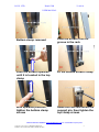
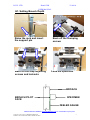
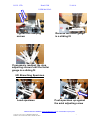
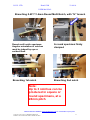
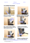
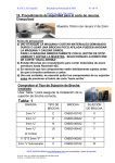
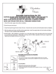
R.J.W. LTD.
Hand CNB
23-09-14
USER MANUAL
6 A. Fitting the Broach
1
2
Raise the rack & insert the
support pin
Loosen the top clamp retaining
screws and withdraw the top
clamp a small amount
3
4
Note: top clamp can be removed and rotated 180° for
different broach types
Top clamp position for C &
H type broaches
5
6
Top clamp position for N &
JS type broaches
Lower the rack and remove
the bottom clamp screws
PLEASE VIEW OUR WEBSITE www.blackscharpy.com for consumables & spare parts
© R.J.W. LTD. 2014 ALL RIGHTS RESERVED
SUBJECT TO CHANGE WITHOUT PRIOR NOTICE
1
R.J.W. LTD.
Hand CNB
23-09-14
USER MANUAL
7
8
Bottom clamp removed
9
Slide the broach into the
groove in the rack
10
Push the broach upwards
until it is located in the top
clamp
11
Fit the bottom broach clamp
12
With upwards pressure,
tighten the bottom clamp
screws
Raise the rack and insert the
support pin, then tighten the
top clamp screws
PLEASE VIEW OUR WEBSITE www.blackscharpy.com for consumables & spare parts
© R.J.W. LTD. 2014 ALL RIGHTS RESERVED
SUBJECT TO CHANGE WITHOUT PRIOR NOTICE
2
R.J.W. LTD.
Hand CNB
23-09-14
USER MANUAL
6B. Setting specimen Axial Position
1
2
Load 10mm specimen into
clamp assembly so that the
specimen is contacting the
axial adjusting screw
Check axial position and
broach a specimen
3
4
Check axial position and
re-adjust position if
required
Always tighten the locking
nut, so securing the axial
adjusting screw position
PLEASE VIEW OUR WEBSITE www.blackscharpy.com for consumables & spare parts
© R.J.W. LTD. 2014 ALL RIGHTS RESERVED
SUBJECT TO CHANGE WITHOUT PRIOR NOTICE
3
R.J.W. LTD.
Hand CNB
23-09-14
USER MANUAL
CUSTOMER TO CHECK AXIAL POSITION,
WITH THEIR OWN EQUIPMENT
Notch to left of specimen centre line, by say 0.010”
1. Initial notch position
Adjusting screw
2. Unclamp specimen
3. Move specimen using
0.010” feeler gauge
4. Clamp specimen
5. Reposition adjusting
screw
Feeler gauge
Notch to right of specimen centre line, by say 0.010”
1. Initial notch position
Adjusting screw
2. Reposition adjusting
screw using 0.010” feeler
gauge
3. Unclamp specimen
4. Move specimen
5. Clamp specimen
Feeler gauge
PLEASE VIEW OUR WEBSITE www.blackscharpy.com for consumables & spare parts
© R.J.W. LTD. 2014 ALL RIGHTS RESERVED
SUBJECT TO CHANGE WITHOUT PRIOR NOTICE
4
R.J.W. LTD.
Hand CNB
23-09-14
USER MANUAL
6C. Setting Broach Depth
2
1
Raise the rack and insert
the support pin
Back off the clamping
screws
4
3
Back off the stop adjusting
screws and locknuts
Load the specimen
BROACH
BROACH PILOT
FACE
SPECIMEN
FEELER GAUGE
PLEASE VIEW OUR WEBSITE www.blackscharpy.com for consumables & spare parts
© R.J.W. LTD. 2014 ALL RIGHTS RESERVED
SUBJECT TO CHANGE WITHOUT PRIOR NOTICE
5
R.J.W. LTD.
Hand CNB
Table 1
23-09-14
USER MANUAL
NOTCH
BROACH
TYPE
BROACH
FEELER GAUGE
THICKNESS
2mm ‘V’
C
CNB30-027A2
0.005”
2mm “U”
P
CNB30-006A2
0.016”
2mm ‘U’
N
CNB30-005A2
0.055”
3mm ‘U’
N
CNB30-005A2
0.016”
5mm ‘U’
JS
CNB30-004A2
0.005”
(2 Cuts)
0.13”/3.3mm “V”
1st CUT
H
CNB30-002A2
0.004”
6
5
Set feeler gauge thickness as
in table 1 and place between
the broach pilot face and the
specimen face
7
Advance the stop adjusting
screws, so that the feeler
gauge is a sliding fit
8
Ensure the stop adjusting
screws are equally adjusted
Tighten the stop adjusting
screw locknuts
PLEASE VIEW OUR WEBSITE www.blackscharpy.com for consumables & spare parts
© R.J.W. LTD. 2014 ALL RIGHTS RESERVED
SUBJECT TO CHANGE WITHOUT PRIOR NOTICE
6
R.J.W. LTD.
Hand CNB
23-09-14
USER MANUAL
9
10
Tighten the clamping
screws
Recheck the feeler gauge
is a sliding fit
11
If necessary readjust the stop
adjusting screws until the feeler
gauge is a sliding fit
6D. Broaching Specimen
1
2
Load specimen
Push specimen up against
the axial adjusting screw
PLEASE VIEW OUR WEBSITE www.blackscharpy.com for consumables & spare parts
© R.J.W. LTD. 2014 ALL RIGHTS RESERVED
SUBJECT TO CHANGE WITHOUT PRIOR NOTICE
7
R.J.W. LTD.
Hand CNB
23-09-14
USER MANUAL
4
3
Clamp specimen using
clamping screws
5
Clamping pins securing the
specimen
6
Apply cutting oil to the
Hold handle & remove
broach teeth, using brush
rack supporting pin
supplied with machine.
We recommend RTD metal cutting liquid
8
7
Rotate the handle at an
even rate to cut the notch
Stop when the broach has cut the
notch and the top clamp has
come to rest on the specimen
Note: To prevent damage to broach teeth always
remove specimen BEFORE raising the broach
PLEASE VIEW OUR WEBSITE www.blackscharpy.com for consumables & spare parts
© R.J.W. LTD. 2014 ALL RIGHTS RESERVED
SUBJECT TO CHANGE WITHOUT PRIOR NOTICE
8
R.J.W. LTD.
Hand CNB
23-09-14
USER MANUAL
9
10
Release the clamping screws,
raise the rack 1mm and remove
the specimen
Specimen broached
12
11
Raise the broach
13
Fit rack support pin
14
Clean broach teeth using
wire brush supplied with
machine, ensuring cuttings
are removed from teeth
gulley’s
Thoroughly clean clamping
area using brush supplied.
The machine is now ready to
cut next notch
PLEASE VIEW OUR WEBSITE www.blackscharpy.com for consumables & spare parts
© R.J.W. LTD. 2014 ALL RIGHTS RESERVED
SUBJECT TO CHANGE WITHOUT PRIOR NOTICE
9
R.J.W. LTD.
Hand CNB
23-09-14
USER MANUAL
6 E. Adjusting Depth of Cut
1
2
Check notch depth
Adjust the feeler gauge
size, by the change in
depth required
Note:
If the depth of notch needs to be
increased, reduce the feeler
gauge size.
If the depth of notch needs to be
reduced, increase the feeler
gauge size.
PLEASE VIEW OUR WEBSITE www.blackscharpy.com for consumables & spare parts
© R.J.W. LTD. 2014 ALL RIGHTS RESERVED
SUBJECT TO CHANGE WITHOUT PRIOR NOTICE
10
R.J.W. LTD.
Hand CNB
23-09-14
USER MANUAL
6 F. JS BROACHING, 5mm U notch
1
2
1st cut. Use feelers as in
Table 1 to set the broach
depth
1st cut completed,
producing a 3mm deep
notch
3
2nd cut. Place the 2mm packer,
supplied with the broach, behind
the specimen to produce a 5mm
deep notch
PLEASE VIEW OUR WEBSITE www.blackscharpy.com for consumables & spare parts
© R.J.W. LTD. 2014 ALL RIGHTS RESERVED
SUBJECT TO CHANGE WITHOUT PRIOR NOTICE
11
R.J.W. LTD.
Hand CNB
23-09-14
USER MANUAL
10 G. SUB SIZE SPACER (OPTION)
For 10mm square and 10 x 7.5mm sub-size specimens, NO SPACER is
required.
For 10 x 5.0mm sub-size specimens, SPACER CNB35-033A4 is required.
For 10 x 4.0mm sub-size specimens, SPACER CNB35-030A4 is required.
For 10 x 3.3 and 3.0mm sub-size specimens, SPACER CNB35-029A4 is
required.
For 10 x 2.5mm sub-size specimens, SPACER CNB35-032A4 is required.
Fixing the spacer
The spacer is held in place by 2 countersunk slotted screws. If the spacer is
removed to broach 10mm square or 10 * 7.5mm subsize specimens, secure the
2off countersunk slotted screws in the fixing holes, to prevent the broach
cuttings from entering the holes.
PLEASE VIEW OUR WEBSITE www.blackscharpy.com for consumables & spare parts
© R.J.W. LTD. 2014 ALL RIGHTS RESERVED
SUBJECT TO CHANGE WITHOUT PRIOR NOTICE
12
R.J.W. LTD.
Hand CNB
23-09-14
USER MANUAL
10 H. MULTI NOTCH (OPTIONS)
The multi notch attachment is
normally fitted at RJW Ltd.,
but can be fitted by customers
who have an engineering
department
10mm square multi notch
specimen
Broaching 10mm Square Multi Notch
1
2
Broaching 1st notch
Broaching 2nd notch
3
Broaching 3rd notch
PLEASE VIEW OUR WEBSITE www.blackscharpy.com for consumables & spare parts
© R.J.W. LTD. 2014 ALL RIGHTS RESERVED
SUBJECT TO CHANGE WITHOUT PRIOR NOTICE
13
R.J.W. LTD.
Hand CNB
23-09-14
USER MANUAL
Broaching 0.45”/11.4mm Round Multi Notch, with “H” broach
Round multi notch specimen.
Angular orientation of notches
must be judged by eye or
scribed lines.
A round specimen firmly
clamped
1
2
Broaching 1st notch
Broaching 2nd notch
Note:
Up to 3 notches can be
produced in square or
round specimens, at a
28mm pitch
PLEASE VIEW OUR WEBSITE www.blackscharpy.com for consumables & spare parts
© R.J.W. LTD. 2014 ALL RIGHTS RESERVED
SUBJECT TO CHANGE WITHOUT PRIOR NOTICE
14