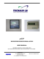
1
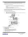
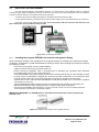
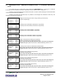
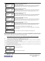
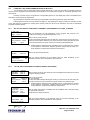
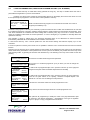
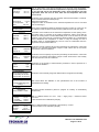
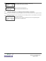
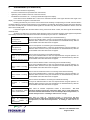
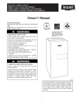
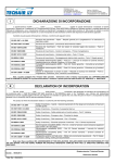
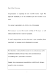
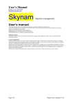
pCO2
MICROPROCESSOR REGULATION
USER MANUAL
THIS MANUAL REFERS TO THE FOLLOWING UNITS:
AIR CONDITIONERS FOR SURGICAL AND CLEANS ROOMS: H and W SERIES
www.tecnairlb.it
[email protected]
TECNAIR LB s.r.l.
Via Caduti della Liberazione 53
21040 UBOLDO (VA)
Tel. +39029699111 / Fax +390296781570
Manuale cod. 75802307A.0403
INDEX:
1.
2.
pCO2 MICROPROCESSOR
3
1.1
1.2
1.4
1.5
1.6
1.7
1.8
1.9
3
3
3
3
5
5
5
5
pCO2 MOTHER BOARD
2.1
3.
6
7
USER TERMINAL MODEL
USER TERMINAL KEYBOARD
TYPICAL USE OF THE BUTTONS IN STANDARD APPLICATIONS
INSTALLING THE USER TERMINAL
7
8
9
10
PROGRAMMING AND CONTROL OF UNIT’S FUNCTIONMENT: (H & W series)
11
4.1
4.2
12
4.3
4.4
4.5
4.6
5
6
pCO2 MOTHER BOARD LAYOUT
USER TERMINAL
3.1
3.2
3.3
3.4
4.
FEATURES COMMON TO ALL THE VERSIONS
FEATURES OF pCO² SMALL (H/R-K)
FEAUTURES OF pCO² LARGE (H series only)
HARDWARE STRUCTURE
MAIN FUNCTIONS
CONTROLLED COMPONENTS
OPTIONS
PROGRAMMING
LOOP MENU: READING OF VALUES SIGNALLED BY THE FEELERS (H & W series)
MANTAINANCE LOOP: COMPONENTS WORKING HOURS H & W SERIES STERILIZATION
CYCLE.
LOOP CLOCK: SETTING OF THE OPERATION (H & W series)
LOOP SET: SET POINTS REGULATION (H & W Series)
LOOP PROGRAMMATION; OPERATION PROGRAM SETTING (H & W SERIES)
LOOP INFO: RELEASE OF THE REGULATION PROGRAM (H & W SERIES)
ALARM MASKS (H & W SERIES)
13
14
15
16
18
19
Manuale cod. 75802206A.0107
Pagina 2 di 23
pCO2 MICROPROCESSOR
1.
The pCO2 represents the evolution of the well-known pCO electronic control. There are of three sizes,
differentiated according to the I/O and power requirements:
pCO 2 SMALL
pCO2 MEDIUM
pCO 2 LARGE.
1.
2.
3.
1.1
FEATURES COMMON TO ALL THE VERSIONS
o
o
o
o
o
o
o
o
o
o
o
o
o
1.2
16-bit microprocessor, 14 MHz, internal registers and 32 bit operation, 512 Byte internal RAM;
up to 6 MByte FLASH MEMORY per program;
256 kByte static RAM, upon prior request expandable to 1 MByte;
1 RS485 serial port for pLAN;
ready for connection to RS485 supervisory network;
clock with replaceable lithium battery;
?
56 Byte of battery backed-up RAM;
?
selection of address and LEDs for pLAN;
?
DIN plastic case for installation on omega rail;
?
24Vac/Vdc power supply;
?
telephone connector for pCO terminals;
?
telephone connector for synoptic;
?
LED power signal.
?
FEATURES OF pCO² SMALL (H/R-K)
o
o
o
o
o
1.3
8 optically-isolated digital inputs, 24Vac 50/60Hz or 24Vdc;
8 relay digital outputs (1 of which with changeover contact);
?
2 analogue inputs, passive between NTC, PT1000, ON/OFF;
?
3 analogue inputs, universal between NTC, 0÷1V, 0÷10V, 0÷20 mA, 4÷20mA;
?
4 analogue outputs, 0÷10 V.
?
FEATURES OF pCO² MEDIUM (H/R-K)
o
o
o
o
o
1.4
14 optically-isolated digital inputs, 24Vac 50/60Hz or 24Vdc; 12 + 2
13 relay digital outputs (1 of which with changeover contact); 10 + 3
?
2 analogue inputs, passive between NTC, PT1000, ON/OFF; 2
?
6 analogue inputs, universal between NTC, 0÷1V, 0÷10V, 0÷20 mA, 4÷20mA; 4
?
4 analogue outputs, 0÷10 V.
FEAUTURES OF pCO² LARGE (H series only)
o
o
o
o
o
o
o
1.5
18 optically-isolated digital inputs, 24Vac 50/60Hz or 24Vdc;
?
? optically-isolated digital inputs, 24Vac/Vdc or 230Vac (50/60Hz);
4
18 relay digital outputs (3 of which with changeover contacts);
?
4 analogue inputs, passive between NTC, PT1000, ON/OFF;
?
6 analogue inputs, universal between NTC, 0÷1V, 0÷10V, 0÷20 mA, 4÷20mA;
?
6 analogue outputs, 0÷10 V;
?
1 serial port for I/O expansion.
?
HARDWARE STRUCTURE
The structure of the pCO2 forecasts:
1.
the pCO 2 control, fitted with a 16-bit microprocessor for running the regulation program, and the set of
terminals required for connection to the controlled devices (for example: valves, compressors, fans). The
program and the set parameters are saved permanently in FLASH memory, prefaning data loss in the event of
power failure (without requiring a back-up battery). The software dowload could be made trow personal
computer or a special programming key. The pCO 2 also allows connection to a local pLAN network made up of
a series of pCO² and terminals. Each board can exchange information (any variable, digital or analogue,
according to the application software) at high transmission speeds. Up to 32 units can be connected, sharing
Manuale cod. 75802206A.0107
Pagina 3 di 23
information in very short times. The connection to the supervisor/telemaintenance serial line, based on the
RS485 standard, is made using the relevant optional serial boards and the Tecnair LB communication protocol.
The local network function is not available for surgical and clean rooms units: series W and H.
2.
the user terminal, also managed by microprocessor, fitted with display, keypad and LEDs is connected to
pCO² mother board. The user terminal allows:
o
o
o
o
o
the initial programming of the machine, with password-protected access to guarantee security;
the possibility to modify, at any time, the fundamental operating parameters, optionally protected by
password;
the display and acoustic signalling (buzzer) of the alarms detected;
the display of all the quantities measured;
the possibility to switch ON and OFF the air conditioner on wich PCO2 in installed.
The connection of the user terminal to the card basic pCO² is not necessary for the regime operation of
the unit. This means that is possible to disconect the terminal from the basic card after the initial
planning of the fundamental parameters.
Tecnair LB provides tree different type of user terminal:
1.
Display LCD 4x20 for wall mounting (cfr. Figura 12).
2.
Display LCD 4x20 for panel mounting (cfr. Figura 13).
3.
Display LCD 16x30 graphic for panel mounting (cfr. Figura 14) for special application: temperature and
humidity monitoring or chinese and cyrillic languages.
Figure 1 : example of pCO 2 connections.
The hardware structure is defined as follows:
1. user terminal with keypad, display and LED signals;
2. pCO2 (SMALL version);
3. pCO2 (MEDIUM version);
4. pCO2 (LARGE version);
5. telephonic type connecting cable between terminal and pCO2 ;
6. . connecting cable AWG20/22 for plan connection of more cards
7. . terminals for a printer (provided by customer) connection;
8. . AWG20/22 cable for connection to a remote monitoring system
9.
connection to the expansion (large card only)
10. . computer for remote control
Manuale cod. 75802206A.0107
Pagina 4 di 23
1.6
MAIN FUNCTIONS
−
−
−
−
−
−
−
Modulating or ON/OFF control of suction and expulsion air temperature.
Modulating control of suction air humidity
Dehumidification control
Complete alarms control.
Units rotation (K and R series).
Hour handing contro
Room overpressure and depressore control (only for series OH and OW)
1.7
CONTROLLED COMPONENTS
−
−
−
−
−
−
−
−
−
1 o 2 compressors.
Tree points (throttling) valve for chilled water coil (K and R series)..
Modulating valve for chilled water coil (K and R series).
Electric resistances with 1step, 2 steps or modulating.
Tree point s (throttling) valve for hot water haeting coil
Modulating valve for hot water haeting coil.
Supply fan
Exaust fan (only for series OH and OW)
Modulating humidifier (trought an external card).
1.8
−
−
1.9
OPTIONS
RS485 serial board for supervisor and telemaintenance
Seriale card for LONWORKS connection.
PROGRAMMING
All the parameters could be setted by the user terminal keypad installed on the unit or by the remote user
interface..
Manuale cod. 75802206A.0107
Pagina 5 di 23
2.
pCO2 MOTHER BOARD
2.1
pCO MOTHER BOARD LAYOUT
2
The following is a description of the pCO2 with reference to the basic layout. (LARGE version).
Figure 2 : layout of base pCO 2.
Manuale cod. 75802206A.0107
Pagina 6 di 23
3.
USER TERMINAL
3.1
USER TERMINAL MODEL
1)
Display LCD 4x20 for wall or panel mounting (pCOT)
FEATURES
–
–
–
Number of rows : 4.
Number of columns : 20.
Font height: 5 mm.
Figure12: Display LCD 4x20 for wall or panel mounting.
2)
Display LCD 4x20 for unit mounting (pCOI):
FEATURES
-
Number of rows: 4.
Number of columns: 20.
Font height: 5 mm
Figure13: Display LCD 4x20 for unit mounting.
3)
LCD Graphic Display for unit mounting (pCOIG)
FEATURES
–
–
Number of rows : 16.
Number of columns : 30.
Figure14: LCD Graphic Display for unit mounting.
The graphic dipaly needs a special control software fitted in one EPROM on the rear side of the graphic
controller (cfr. Figura 15).
Manuale cod. 75802206A.0107
Pagina 7 di 23
REFERENCE FIGURE 15
1. connector to the inverter and signal management card for the
display
2. connector for the optional printer card).
3. telephone-type connector card for terminal connection to the
pCO 2 or junction TCONN6J000
4. buzzer for acoustic alarm signals
5. metal-plated mounting holes
6. connector for connection to an additional keypad card
7. EPROM program and mounting/direction orientation
8. connector for real time clock/32kB EEPROM
9. power connector
10. protective screen.
Figure15: graphiuc dipaly card.
- It is possible to regulate the contrast of every model of display.
The user terminal is used only for programming the machine parameters. The models with a 4x20 LCD display are fitted
with a trimmer for adjusting the contrast of the display. The trimmer can be accessed using a flat-head screwdriver
through the hole located in top-right corner of the rear cover (models PCOT*) or by removing the rear cover (models
PCOI*); in the latter case the trimmer is located on the top-right corner of the main board itself.
For models with graphic display the contrast con be adjusted by simultaneously pressing the Menu and or Menu and
buttons.
3.2
USER TERMINAL KEYBOARD
The terminals just described are endowed with a keyboard (cfr. Figure 16 and 17) that allows:
–
–
–
the planning of the parameters of operation of the conditioner;
the visualization of the state of the conditioner and his/her components;
the lighting and the turning off of the conditioner
Figure 16: Terminal keyboard pCOT. The number 1 indicates the working LED signals.
Figure 17: Terminal keyboard pCOI and pCOIG. The number 1 indicates the working LED signals.
Manuale cod. 75802206A.0107
Pagina 8 di 23
3.3
TYPICAL USE OF THE BUTTONS IN STANDARD APPLICATIONS
BUTTON
NAME
FUNCTION
Menù button
displays the values measured by the feelers
Maintenance button
displays the values relating to the maintenance of the
devices (working hours and operating hour counter
reset);
Printer button
accesses the group of screens
management (where included);
I/O button
displays the status of inputs and outputs (both digital
and analogue);
Clock button
allows the display/programming of the clock (if
present);
Set button
allows the Set-Point setting.
Programming button
allows the various operating parameters to be set
(safety parameters, thresholds)
for
printer
Programming+menu button by pressing simultaneously these buttons you access
the unit configuration
Info button
displays the version of the application program and
other information;.
Orange button
allow to modify the user terminal used.
The LED next to each button are illuminated when the relative function is active
BUTTON
NAME
FUNCTION
On-off button
switches the unit on or off. The green LED that lights
up in the button shows if the machine is turned on;
Alarm button
used for displaying or manually resetting the alarms
and resilencing the buzzer. If the button lights up
(red), at least one alarm has been detected;
Up/downwards arrow button allows to manage the currently displayed screen and
to set the values of the control parameters
Enter button
to confirm the set data. The button is constantly backlit (yellow) indicating the presence of mains power..
The display pCOT foresees on the façade a small tray that opens with a maximum inclination of 150°. With closed small
tray it is only accessed the keys on-off, alarm, arrow up/down and enter. To access the remaining keys is owed to open
the small tray. When the small tray is close are visible only the three LEDs that retroilluminate the keys on-off, alarm and
enter. The other LEDs are only visible to open the small tray.
Manuale cod. 75802206A.0107
Pagina 9 di 23
3.4
INSTALLING THE USER TERMINAL
The connection between the user terminal and pCO 2 is made using a 6-way telephone cable. To make the
connection simply insert the telephone connector in terminal J10 of the pCO 2 and in terminal B on the user terminal.
Insert the connector fully into in the terminal until it clicks into place.
To remove the connector simply press lightly on the plastic flap and remove the cable.
For the model PCOIG only connect the 24Vac (30VA) power supply to the screw terminal block. (cfr. Figura 15).
The pCO2 can also work without the terminal; do not disconnect and then reconnect the terminal to the
pCO 2 without first having waited around 5 seconds
Figure 183: user terminal connection.
3.4.1
Installing the program EPROM in the terminal with graphic display
All the information relating to the management of the graphic display are created by the application software
contained in an EPROM. To install the EPROM be extremely careful when handling this component, keeping
the following in mind:
−
−
−
−
remove the power supplì from the graphic display;
togliere lo schermo di protezione svitando le relative viti;
before touching the EPROM, touch a grounded part to discharge the necessary static electricity
accumulated (do not touch any powered devices);
insert the EPROM in the relative socket on the board, checking that all the pins are inserted correctly
in place (exact correspondence between the pins and the slots; furthermore, do not bend the pins,
carefully inserting them into the socket,holding the component by opposite end to the pins);.
−
verificare che la “tacca” sulla superficie della EPROM sia nella direzione della “tacca” di riferimento serigrafata
sulla scheda (cfr. Figura 19).
−
Once the EPROM has been inserted remount the board which acts a shield or if necessary the
optional printer board, before closing the cover, and place the terminal in operation.
−
Per rimuovere la EPROM è utile l’impiego di un piccolo cacciavite, avendo cura di non rovinare le piste del
circuito stampato o qualche altro componente contiguo.
IMPORTANT WARNING: the EPROM must be inserted/removed from the socket only when the
terminal is off..
Figura 19 installation of the eprom on the graphic terminal.
Manuale cod. 75802206A.0107
Pagina 10 di 23
4.
PROGRAMMING AND CONTROL OF UNIT’S FUNCTIONMENT: (H & W series)
The regulation program is made by he User through the keyboard and gives to the microprocessor the operating
parameters: set points, alarm thresholds a.s.o.
The regulating program can handle:
−
Fans.
−
−
Compressors.
Elettric heating resistences.
−
Modulanting proportional valves: valves controlled by the pCO2 with a 0–10 Vdc signal directly proportioned to
the set range. This means that if the temperature is at the upper limit of the range the signal coming out of the
pCO is of 10 Vdc. Instead, if the temperature is equal to the set-point the outgoing la tensione from the pCO is of
0 Vdc.
−
Three point (Throatling) valves: water valves commanded by the pCO2 with a signal for opening and one for
closing. These valves have an opening time, that represents the necessary time to pass from the position of
complete closing to that of complete opening. Sending the signal of opening or closing for a determined time, it is
possible to open or clos ing (partially) the valve. In this case it is not possible to precisely aknolwledge the position
of the valve. The valves, Throatling or to three points, they are completely closed to the beginning of the
proportional gang, that is in proximity of the set-point, and completely open at the end of the gang. Every time that
a valve to three points, must be activate, the program sends a command of closing to line up the position of the
same valve before beginning the regulation. This operation is not necessary for the valve modulante in how much
in absence of tension it automatically brings him in the position of closing. The point valves are therefore not
installed, and not recommended by Tecnair LB in case of treatment of total or partial, fresh air, since there
reaction time is very long.
Inverter: A device that allows the variation of the feeding frequency of the devices connected to it. In the
conditioners of the H series produced by Tecnair this is employed for modulating the power of the compressor to
draw nearer the temperature to the planned set-point (only for heat pump units) and to check the supply and
expulsion fan. The inverter is commanded by the pCO2 with a 0-10 Vdcs signal.
Hot gas injection: to regulate the cooling capacity in relation to the room temperature. Regulation with hot gas
injection, possibly assisted by the electronic expansion valve for a perfect control of capacity, is controlled by the
PCO2 with a 10 – 100 v.
−
−
−
Modulaning humidifier: device for the production of humidity.
All the formulations can be effected on units on board terminal or on the one installed in the environment
(accessory), since the two terminals are equivalent entirely.
The climatization software for the surgical rooms offers the possibility to be able to plan up to 10 regulation
programs, easily modifiable by the user. Besides, a program exists for maintaining the unity in night stand-by is a
program to do the sterilization of the surgical room. These programs are retrievable from the programming procedure
describe din this chapter.
Manuale cod. 75802206A.0107
Pagina 11 di 23
4.1
LOOP MENU: READING OF VALUES SIGNALLED BY THE FEELERS (H & W series)
You accesses this loop of masks after having pressed the Menu key. In this loop of masks the values are
visualized and read by the existing feelers. To this intention we remember that the temperature/humidity feeler for the
environment , external and anti freeze temperature, this is the only feeler to be always present.
Pressing once the key Menu ignites the corresponding led and on the display the mask that points out: - the
value of the temperature environment; is visualized.
- the value of the damp environment (the indication of damp is different only from zero if the probe of damp is
present);
- the time and the actual date;
- the state of the unit (ON-OFF).
By Pressing the keys Increase and Decrease it is possible to flow through the loop of masks of menu. Following
this the loop of the masks of menù is brought
12:14
08/07/2001
Temperature
20.0ßC º It displays the time and date
Humidity
50.0ur%º It displays the values of temperature and humidity of the ambiance.
It displays the units status
* UNIT OFF *
Supply air
00.0º
Supply humid. 00.0%º
Ext.air
00.0ßC º
Ext.humid.
00.0ur%º
Supply air temperature/humidity value
Fresh air/humidity temperature values
Value of the anti-frost temperature
Antifreeze
00.0ßC
Room press.
000.0PA Value of over/under pressure of the room in relationship to the reference
Air deliv.
00000mc/h environment. Standard for units of series H and W.
Supply air flow value Standard for units of series H and W.
Defrost 1
Defrost 2
0,00°C
0,00°C
Steam prod. #1 00.0 Kg/h
Steam prod. #2 00.0 Kg/h
Enthalpy
Set point
Ent.int.
Ent.ext.
00.000kc/kj
00.000kc/kj
00.000kc/kj
Air flow not obtained
Pressure not obtained
It displays the values of defrost #1
It displays the values of defrost #1
Mask visualised only for heat pump units.
Steam production during humidification request
Warning: mask not used; it is provided but is not active as the enthalpic free cooling
functioning is not provided
It displays the optimal/non-optimal air flow/pressure with regard to the sets required
(tolerance +/- 10%)
Manuale cod. 75802206A.0107
Pagina 12 di 23
4.2
MANTAINANCE LOOP: COMPONENTS WORKING HOURS
CYCLE.
H & W SERIES STERILIZATION
You access this loop of masks after having pressed the MANTAINANCE key.. In this loop of masks the
functioning hours are visualised for the main components of the air conditioner (fans, compressors….)
Pressing once the maintenance key the relative leds switch on and the masks indicating the functionment hours
of the fans and compressors is visualised.
Pressing the increase and decrease keys it is possible to scroll throguh the mantainance mask loop. The
following is the mantainance mask loop.
ba Time counter
Unit
00000
Compressor 1
00000
Compressor 2
00000
It display the functioning hours of the unit (by referring to the main fan)
and of the compressor(s).
bb Time counter
Heat. post. 1
00000
Heat. post. 2
00000
Functioning hours of the electric post heaters # 1 (if present)
Functioning hours of the electric post heaters # 2 (if present)
bc Time counter
Humid.#1
00000
Humid.#2
00000
Functioning hours of the humidifier # 1 (if present)
Functioning hours of the humidifier # 2 (if present)
bd Time counter
Heater.#1
00000
Heater.#2
00000
Functioning hours of the electric heaters # 1(if present)
Functioning hours of the electric heaters # 1(if present)
be Insert.counter.
Compressor 1
00000
Compressor 2
00000
Reset #1No
#2No
Number of compressors # 1starting ups (if present)
Number of compressors # 2 starting ups (if present)
How to reset: the enter key will move the cursor; the arrow will change the
parameter into “yes” (after a few seconds, it will automatically go back to “no”).
bf Unit
Working hours
Threshold
Reset
Functioning hours of the unit Threshold for indicative alarm
How to reset: the enter key will move the cursor; the arrow will change the
parameter into “yes” (after a few seconds, it will automatically go back to “no”).
00000
00000
No
bg Compressor 1
Working hours
00000
Threshold
00000
Reset
No
Functioning hours compressor #1 (if present)
Threshold for indicative alarm
How to reset: the enter key will move the cursor; the arrow will change the
parameter into “yes” (after a few seconds, it will automatically go back to “no”).
bh Compressor 2
Working hours
00000
Threshold
00000
Reset
No
Functioning hours compressor #2 (if present)
Threshold for indicative alarm
How to reset: the enter key will move the cursor; the arrow will change the
parameter into “yes” (after a few seconds, it will automatically go back to “no”).
bi Humidifier 1
Working hours
Threshold
Reset
Functioning hours humidifier #1(if present)
Threshold for indicative alarm
How to reset: the enter key will move the cursor; the arrow will change the
parameter into “yes” (after a few seconds, it will automatically go back to “no”).
00000
00000
No
Manuale cod. 75802206A.0107
Pagina 13 di 23
bJ Humidifier 2
Working hours
Threshold
Reset
00000
00000
No
Functioning hours humidifier #2 (if present)
Threshold for indicative alarm
How to reset: the enter key will move the cursor; the arrow will change the
parameter into “yes” (after a few seconds, it will automatically go back to “no”).
bk Heater 1
Working hours
Threshold
Reset
00000
00000
No
Functioning hours heater #1 (if present)
Threshold for indicative alarm
How to reset: the enter key will move the cursor; the arrow will change the
parameter into “yes” (after a few seconds, it will automatically go back to “no”).
bl Heater 2
Working hours
Threshold
Reset
00000
00000
No
Functioning hours heater #2 (if present)
Threshold for indicative alarm
How to reset: the enter key will move the cursor; the arrow will change the
parameter into “yes” (after a few seconds, it will automatically go back to “no”).
bm Heater post 1
Working hours
00000
Threshold
00000
Reset
No
Functioning hours post heater #1 (if present)
Threshold for indicative alarm
How to reset: the enter key will move the cursor; the arrow will change the
parameter into “yes” (after a few seconds, it will automatically go back to “no”).
bn Heater post2
Working hours
00000
Threshold
00000
Reset
No
Functioning hours post heater #2 (if present)
Threshold for indicative alarm
How to reset: the enter key will move the cursor; the arrow will change the
parameter into “yes” (after a few seconds, it will automatically go back to “no”).
Bo Sterilization cycle
Disabilitated
Damper
099%
Mask which allows for the abilitation of the sterilization cycle.
This mask is active only for untis of the H series provided with air recirculation
motorised damper.
Bp Cleaning cycle
Cycle #1
01 hours Mask which allows for the settino and abilitation of the cleanign cycle.
Cleaning
01 hours
NOTE: To reset the hours of operation of the components, It is necessary to press ENTER up to bring the cursor under
the writing N. So to perform the reset it is necessary to press the increase or decrease key up to when the writing Y
appears. At this point release the key and wait for the writing N to appears.
Planning 0000 as threshold value for the times of operation the operation alarm will never be had.
4.3
LOOP CLOCK: SETTING OF THE OPERATION (H & W series)
You access this loop of masks after having pressed the Clock key. In this loop of masks it is possible to
visualize and to plan the current time and the current date.
Pressing once the key clock ignites the corresponding led and on the display the mask is visualized for the
visualization of the date and the current time.
By pressing the Increase and Decrease key it is possible to flow through the loop of the masks related to the
clock. What follows is the loop of the masks of the clock.
ea
Date
Hour
Clock
00/00/00
00:00
eb
Clock set
gg/mm/aa 00/00/00
hh:mm
00:00
Mask reading date and time.
Mask for date and time introduction
Manuale cod. 75802206A.0107
Pagina 14 di 23
4.4
LOOP SET: SET POINTS REGULATION (H & W Series)
You access this loop of masks after having pressed the set key. In this loop of masks it is possible to plan the
set-point for the regulation of the temperature and humidity in the environment, brought air, over/under pressure in the
environment,
Pressing once the set key Set ignites the corresponding led and on the display the mask is visualized for the
formulation of the set-point of temperature.
By pressing the increase and decrease keys it is possible to flow through the loops of the set masks.
Following this the loop of the set masks is brought up. The following two loops of masks are suitable: the first
one is valid when the conditioner is working in the sand-by mode, the other one is valid when one of the 10 selectable
programs has been chosen.
4.4.1
SET KEY OF THE AIR CONDITONER IN NORMAL FUNCTIONMENT FOR H AND _W SERIES
fa Set Point -Temp.
Mask for introduction the set temperature for the program with which the air
conditioner is working (cfr programming branch 12.7)
23.0 °C
Fb
Room pressure 020.pa
Damper
100%
Mask to set the room pressure
and the recirculation damper during the stand by (value wuhich can be set only in
presence of recirculation damper). The air flow of the unit during the stand-by must
be 1/3 of the nominal et not under 1500 mc/h to dilute the anhestetical gas.
(1) Positive pressure means that the controlled room is in overpressure in respect
to the reference environment. Negative pressure means that the room is in
under pressure in respect to the reference environment.
fb Humidifier Humidity
55.0 ur%
ff Humidifier -Manual drain:
(120 sec of timeout)
4.4.2
Mask to set the humidity set-point
Mask for manual activation of the solenoid valve for water unloading of the
NO humidifier (useful in case of substitution of the cylinder).
OF THE AIR CONDITIONER IN STAND-BY MODE (H & W SERIES)
fa Set Point --stand by
Temp.MIN
15.0 °C
Temp.MAX
29.0 °C
Mask to set the minim um and maximum room air temperature the unit has to control
during the stand-by function
fb
Mask to set the air flow,
Air flow
1500mc/h the room pressure
Room pressure 020 Pa and the recirculation damper during the stand by. The air flow of the unit during the
Damper
100 %
stand-by must be 1/3 of the nominal et not under 1500 mc/h to dilute the gas.
(1) Positive pressure means that the controlled room is in overpressure in respect
to the reference environment. Negative pressure means that the room is in
under pressure in respect to the reference environment.
fc Stand by -Humid. Min. 30 %
Humid. max. 70 %
Production
03 kg/h
Mask to assign the interval of humidity that the conditioner has to maintain during
the operations in stand-by.
Introductions for steam production.
fe Humidifier #1
Manual drain NO
(120 sec of timeout)
Mask for manual activation of the solenoid valve for the water unloading of the
humidifier (useful in case of substitution of the cylinder).
Manuale cod. 75802206A.0107
Pagina 15 di 23
4.5
LOOP PROGRAMMATION; OPERATION PROGRAM SETTING (H & W SERIES)
You access this loop of masks after having pressed the Prog key. This loop of masks allows the user to
personalize the regulation in upon his own demands.
Pressing once the Prog key ignites the corresponding led and on the display the mask for the choice of one of
the ten previously set programs is or for the choice of the operation in stand-by.
ga
Progr.stand-by enable Si
ON 16:00
OFF 06:00
Program
N°>01<
Mask to recall the stand-by program or to make the unit work with one of the 10
programs pre installed (1-10).
Introduction the program in stand-by it is necessary to plan the interval of time in which the conditioner has to work with
the conditions planned for in stand-by operation (brought redoubt, greater tolerance for temperature and humidity). In the
case above described the conditioner has been working later in stand-by every day from 16:00 to 06:00, moment in
which the conditioner takes back the normal operations. In case of emergency it is possible to manually disarm the
operation in stand-by.
This operation is done by setting NO in the previously described mask. As an alternative an external command
forecasted by TECNAIR LB can be installed for the activation of this function.
In case the the stand by from a remote position the unit will contiue working with reduced capacity up to a new
command.
If the unit is placed in stand by from remote it is not possible to reset the unit to normal functionm ent from it’s terminal
location.
Pressing once the down key arrow a mask appears for the insertion of the password for the access to the user planning
masks. After having inserted the correct password for the user (0123 is the default) it is possible to flow the loop of the
user planning masks by pressing the increase and decrease keys. The following is the loop of the masks for the user
planning..
gb
Insert the user password
0000
This function is to allow introducing the user password
gc
Select the program N 01
This function is to recall the programme (1-10) of which you want to change the
parameters.
gd Program
#01
It is valid for all 10 programmes (the one in question is shown up on the right) and
SETPOINT
changes the set point values of ambient temperature and humidity
Temperature
20.0°C
Humidity
55.0UR%
ge program
#01
It is valid for all 10 programmes (the one in question is shown up on the right) and
Air flow
1500mc/h varies the set point values of air capacity, ambience overpress./depres. and
Room pressure 020 Pa external air % in case of re-circulating air-locks presence.
External air
100 %
gf
Its function is to record the values of a certain programme ex.>01<.
Save the dates in program
N°>01<
Gg
Safety mask to record the changed values of a certain programme ex.01
Are you sure to save
dates in program N°01?
YES/NO
gh Type Prop+ Int
Mask (valid for all programmes) to modify the value of the proportional band (see
Integr. Tinme
the meaning in the relevant paragraph) – determination of the type of regulation
Band temp.:
03.0°C (propor. or propor.+ integr.)- integration time introduction.
Manuale cod. 75802206A.0107
Pagina 16 di 23
gi
Alarm's offset
High Temp.:
Low Temp.:
gj Hot/Cold
05.0 °C
05.0 °C
Mask to determinate of the alarm thresholds for low and high room temperature.
Thresholds are connected with the temperature set point (ex. By introduction
5°C for high and 5°C for low temperature, with a 20°C introduction, the high
temperature alarm will occur at 25°C, while the low temperature alarm will
occur at 15°C).
AUTO
Introduction of the passage type with automatic hot/cold functionment or external.
This is a valid introduction for heat pumps.
Neutral zone
01,0°C Neutral zone introduction
Off compressors
SI
Compressor swith of introduction if the external temperature is two low and slow
Delay
060 sec down of switching of.
gk
Circulator Delta
Setting of the temperature difference between fresh and suction air of the room for
the activation of the circulator for heat recovery (Heat Recovery units only; HR)
gl
Formulation of the threshold of the external air temperature for the opening of the
warm water valve or activation of the heating resistances used to avoid that the
batteries for cooling freeze. The first differential points out of the value for the total
activation of the warm water (it is activated to threshold-differ. #1). The differential
second establishes the temperature to which to stop the sending fan and of
expulsion (block to threshold-differ.#2). The two fans are reactivated when the
temperature is equal to limit+differ. #1
Antifreeze
Threshold
Differ. #1
Differ. #2
00.0°C
00.0°C
00.0°C
gm Set point
Air flow
External air
Introduction if the air capacity set point and percentage of external air in case of the
presence of a motorized recirculation camper. These values refer to the normal
4300mc/h functionment of the air conditioner.
100%
gm Stand-by
Air flow
External air
Introduction if the air capacity set point and percentage of external air in case of the
4300mc/h presence of a motorized recirculation camper. These values refer to the standby
100%
mode functionment of the air conditioner.
gn Steam production
Prod #1
Kg/h
Prod #2
Kg/h
Introduction of the quantity of network steam production in case of presence of a
steam network distributor
go Humidification
Band humid 00.00 UR%
Introduction of the humidity range and relative alarms of high and low humidity
Low humidity 00.00 UR%
High humidity 00.00 UR%
gp umi-cooling
Use humidification plus
cooling ? ?
Gq ID user
0000000000
History enabled SI/NO
gr Room temp.
Supply.
Humidity.
Ext.humidity
gs
Antifreeze
Ext.temp.
Air flow
0.0°C
0.0°C
0.0ur%
0.0ur%
Mask which allows the abilitation to the symulatneous use of the functions of
humiditifcation and chilling.
Unit serial number introduction (useful to program an ordinary or extraordinary
maintenance)
Mask to calibrate feelers for room temp. / supply temp. / ambience humid.
/ext.humid.
In case of feelers out of calibration (sample)
Mask to calibrate feelers for antifreeze / external temp. / air flow
0,0°C
in case of feelers out of calibration (sample)
0.0°C
00000 mc/h
Manuale cod. 75802206A.0107
Pagina 17 di 23
gt
Room press
Defrost.1
Defrost 2
ga
Insert the new
password 0000
4.6
0,0 Pa
0,0βC
0,0βC
Mask to calibrate feelers for room pressure. / defrost temp.
In case of feelers out of calibration (sample)
Mask to insert the new user password
user Note: the original password will still be valid .
LOOP INFO: RELEASE OF THE REGULATION PROGRAM (H & W SERIES)
This mask is accessed after having pressed Info key. This mask contains information on the regulation software
version.
Pressing once the info key the corresponding led on the display switches on and visualises the information
mask on the regulation program.
Short software description.
ga
Identification of the air conditioner inserted by the user in the programming phase.
Progr.stand-by enable Si
ON 16:00
OFF 06:00 Software version and validation date
Program
N°>01<
Manuale cod. 75802206A.0107
Pagina 18 di 23
ALARM MASKS (H & W SERIES)
5
-
Each alarm situation is signaled by:
Activation of the buzzer incorporated in the user terminal;
Lightening of the red led on the front of the user terminal;
Visualization of the words "AL" on the right hand side angle of the display.
Each alarm mask is identified with a code of two characters situated in the higher left hand side angle of the
display, so to ease the recognition of the mask itself.
Pressing the alarm key the buzzer sound is silenced the message corresponding to the last activated alarm s
visualised. With the increase and decrease keys it is possible to scroll through all the alarm signals memorized. Pressing
once more the alarm key the memorized alarm signals are cancelled only after having eliminated the alarm’s cause. All
alarms are manually reset.
If the alarm signals are cancelled without having removed the alarm causes, the alarm signal will immediately
reactivate itself.
All alarms are delayed by one minute at the activation of the unit, with the exception of the high/low temperature
and humidity alarms and also the broken feeler alarm are delayed by the user for a settable time.
XA
Compressor
functioning hours
Alarm for Compressor 1’s functioning hour threshold reaching.
1 This is just an indication alarm. It does not compromise the units good operation. To
delete this alarm reset the hours (see mantainance as described before). With the
Tecnair default values this alarm does not appear.
XB
Compressor 2
functioning hours
Alarm for Compressor 2’s functioning hour threshold reaching.
This is just an indicative alarm. It does not compromise the unit good operation. To
delete this alarm reset the hours (see mantainance as described before). With the
Tecnair default values this alarm does not appear.
XC
Supply air fan functioning
hours
Exaust fan functiong hours
Alarm for the fan functioning hour threshold reaching.
This is just an indicative alarm. It does not compromise the unit good operation. To
delete this alarm reset the hours (see mantainance as described before). With the
Tecnair default values this alarm does not appear.
XD
Alarm for the first electric heater’s functioning hour threshold reaching.
This is just an indicative alarm. It does not compromise the unit good operation. To
Electric heater 1 functing delete this alarm reset the hours (see mantainance as described before). With the
Tecnair default values this alarm does not appear.
hours
XE
Alarm for the second electric heater’s functioning hour threshold reaching.
This is just an indicative alarm. It does not compromise the unit good operation. To
Electric heater 2 functing delete this alarm reset the hours (see mantainance as described before). With the
Tecnair default values this alarm does not appear.
hours
XF
Humidifier
hours
1
Alarm for the first humidifier’s functioning hour threshold reaching.
functiong This is just an indicative alarm. It does not compromise the unit good operation. To
delete this alarm reset the hours (see mantainance as described before). With the
Tecnair default values this alarm does not appear.
XG
Feeler alarm for ambient temperature broken or disconnected.
The unit
Room temperature feleer continuoes working leaving the component active (hot or cold component).
This alarm indicates that the feeler is not connected to the microprocessor, or
broken or disconected
that the microprocessor is reading a value out of it’s range.
XH
Supply air temperaure
feeler
broken
or
disconnected
Feeler alarm for supply air temperature broken or disconnected. The unit
continues working. This alarm indicates that the feeler is not connected to the
microprocessor, or that the microprocessor is reading a value out of it’s
range.
Manuale cod. 75802206A.0107
Pagina 19 di 23
XI
External
temperature
feeler
broken
or
disconnected
Feeler alarm for external temperature broken or disconnected. The unit continues
working. This alarm indicates that the feeler is not connected to the
microprocessor, or that the microprocessor is reading a value out of it’s
range.
XJ
Feeler alarm for ambient humidity broken or disconnected. The unit continues
working. This alarm indicates that the feeler is not connected to the
Humidity feeler broken or microprocessor, or that the microprocessor is reading a value out of it’s
range.
disconnected
XK
Feeler alarm for external humidity broken or disconnected. The unit continues
working. This alarm indicates that the feeler is not connected to the
External humidityt feeler microprocessor, or that the microprocessor is reading a value out of it’s
range.
broken or disconnected
XL
Feeler alarm for air capacity fan 1 broken or disconnected. The unit continues
working. This alarm indicates that the feeler is not connected to the
Differential
pressosta microprocessor, or that the microprocessor is reading a value out of it’s
range.
broken or disconnected
XM
Feeler alarm for ambient pressure broken or disconnected. The unit continues
working. This alarm indicates that the feeler is not connected to the
Room pressure feeler microprocessor, or that the microprocessor is reading a value out of it’s
range.
broken or disconnected
YR
Defrost feler temperare compr.1 broken or disconnected. The unit continues
working. This alarm indicates that the feeler is not connected to the
Defrost feler temp. ompr.1 microprocessor, or that the microprocessor is reading a value out of it’s
range.
broken or disconnected
YS
Defrost feler temperare compr.2 broken or disconnected. The unit continues
working. This alarm indicates that the feeler is not connected to the
Defrost feler temp. ompr.1 microprocessor, or that the microprocessor is reading a value out of it’s
range.
broken or disconnected
XN
External air filter clogged
Alarm for external air intaking pre-filter clogged.
XO
Supply air filter clogged
Allarm for supply air filter clogged. It dosen’t stop the unit
XP
Suction air filter clogged
Alarm for suction air filter clogged
XQ**SERIOUS ALARM
Fire /fume
** UNIT OFF **
XR
*
Alarm for fume/fire presence. It stops the unit.
Alarm of anti-frost intervention for very low temperature.
Antifreeze
XS
Eeprom broken
Alarm for eprom failure.
Manuale cod. 75802206A.0107
Pagina 20 di 23
XT
General
compressor 1
Alarm for comp.1’s high pressure or technician intervention It doesn’t stop the unit.
alarm Warning: manual reactivation of the pressostat required after having found
out the cause of the alarm.
XU
Alarm for comp.1’s high pressure or technician intervention It doesn’t stop the unit.
alarm Warning: manual reactivation of the pressostat required after having found
out the cause of the alarm.
General
compressor 2
XW
Low pressure
comprressor 1
Alarm for low pressure switch intervention.
It doesn’t stop the unit but only the component .
Warning: the pressostats reactivation is automatic but the alarm need to be
manual reactivated whilst the compressor can automatically restart.
Low pressure
comprressor 2
Alarm for low pressure switch intervention.
It doesn’t stop the unit. Warning: the pressostats reactivation is automatic but
the alarm need to be manual reactivated whilst the compressor can
automatically restart.
XX
XY
thermical rehating coil
Intervention of the coil for the protection of the electric post heating coil. To reset
the alarm the reset of the thermical is necessary.
YA
This alarm indicates the intervention of the electric coil themrical protection (manual
reset of the themrical required). Or thetripping alarm for the intervention of the
elctrical resistance thermostat. The thermostats are 2: the first interviens at 70°C
aand has automatic rearmament. The second thermostat, a security measure,
interviens 95°C and has manual rearmament. The unit continuous functioning .
Heating coil thermal
YB** SERIOUS ALARM **
Supply air fan thermal
Alarm for thermal protection intervention for supply air temperature n°1. The unit
protection n°1
continous working if the doubly fan is present (accessory) otherwise the unit stops.
** UNIT OFF **
YC
Exaust air fan thermal
protection
Tripping alarm for the thermic expulsion fan n°1.
This alarm is not considered as a cause to stop the unit since in case of emergency
it is simply a case of leaving a door slightly open. The alarm stops the unti in case
of working in depression.
YD
** SERIOUS ALARM *
Supply air fan
** UNIT OFF **
Allarme di stato del fane di mandata. L’unità si spegne.
YE
Alarm status for the expulsion fan.
Expulsion fan status
YH
High room temeparture
YI
Low ambient temperature
Alarm for high ambient temperature which is reached once the set limit is reached
and the time set. It does not stop the unit
Alarm for low ambient temperature which is reached once the set limit is reached
and the time set. It does not stop the unit
Manuale cod. 75802206A.0107
Pagina 21 di 23
YL
Water circulator alarm . Only for units withheat recovery coils.
Circulator alarm
YM
** SERIOUS ALARM *
Damper status
** UNIT OFF **
Alarm for damper status.
UNIT OFF
YV
Flooding alarm. It does not stop the unit.
Flooding alarm
Allarme E06
High humidifier
current
1
/
2 Alarm for high current absorption measured by the TAM of the humidifier 1 / 2.
Allarme E09
lack of water in the
humidiifer 1 / 2
Alarm for lack of water in the humidifier
The lack of water is measured by the level sensors placed on the cylinder.
Alarm E10
Alarm for lack of current in the humidifier
Lack of current humidiifer
The high tension is measured by the level sensors placed on the cylinder.
1/2
Alarm E12
Alarm for low ambient humidity
Low ambient humidity
Alarm E11
Alarm for high ambient humidity
High ambient humidity
YN
Alarm which indicates that one or more card do not communicate with one another.
not communicating
YO
Post heating 1
functiong hors
Alarm for re-heating heater 1’s functioning hour threshold reaching].
heater This is just an indicative alarm. It does not compromise the unit good operation
YP
Post heating 2
functiong hors
Alarm for re-heating heater 2’s functioning hour threshold reaching].
heater This is just an indicative alarm. It does not compromise the unit good operation
Alarm for supply humidity feeler broken or disconnected
XR
Supply humidity feeler The unit continues working. This alarm indicates that the feeler is not
connected to the microprocessor, or that the microprocessor is reading a
broken or disconnected
value out of it’s range.
YS
Humidifier
hopurs
2
functiong
Alarm for humidifier 2’s functioning hour threshold reaching].
This is just an indicative alarm. It does not compromise the unit good operation
YT
Allarm for low supply air temperature.
Low supply air temp
Manuale cod. 75802206A.0107
Pagina 22 di 23
Yz
Intervention alarm for thermical supply fan n°2 status
Supply fan status n°2
Ka
Thermical status expulsion fan n°2
Thermi expulsions fan n°2
Ke
Alarm for terminal filter
dirty
Terminal filter dirty alarm
No active alarm
NO ALARM
Manuale cod. 75802206A.0107
Pagina 23 di 23