1
,,
ic>
SRL-250 .
USER'S
MANUAL
s
sjN
RJ_:Zo-o c. 3201-os-
2-/2.-Jos-
Servo
Reciprocating
Linear
Die Spray
System
I
Features
3
Technical
5
Specifications
Unpacking and
7
Setup
Programming
9
Troubleshooting 21
Maintenance and
31
Adjustments
Replacement
Parts
33
Technical
45
Documentation
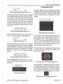
FEATURES
The Advance SRL-250 die sprayer is
designed to be used with both zinc and
aluminum die cast machines, ranging in size
from 150 ton to 400 ton machines . The unit
is controlled by an industry proven
Mitsubishi FX1 s series programmable logic
controller. Programming is done through a
menu driven , two line back lit liquid crystal
display, using push buttons for data entry.
There is program storage for up to 8
different programs. Programs can have up
to 20 different spraying positions. At each
position, the unit can spray lube , blow off
the dies, or perform both actions a once.
consists of a 3/8" lube valve, a 3/4" spray
air valve with pressure regulator, and a 3/
4" air blast valve .
The main control cabinet for the SRL-250
is a wall mount Nema 12 rated cabinet. The
overall size of the cabinet is 8-1/2" deep x
15-3/4" wide x 19-3/4" tall. Twelve foot
cables come standard with the control
cabinet. The control cabinet needs 120 VAC
to run.
The SRL-250 has two axis of movement,
vertical and horizontal. The vertical axis
movement is servo driven. The servomotor
is coupled directly to a gear box which is
then connected to a belt driven linear
actuator. The top speed of the vertical axis
is 72 in/sec.
The vertical axis is
programmed through the HMI on the main
control panel. The horizontal axis is
manually adjusted. The horizontal axis
can be adjusted 8-1/2" to accommodate
various die thickness' . In addition, to help
with die change outs, both the vertical and
horizontal axis can be rotated about the
base to provide the needed clearance to
remove the dies.
As a standard , the SRL-250 comes with a 4
spray head, 10" long bar manifold. A 6
head, 15" long manifold is also available . Air
blast is provided with both manifolds.
I
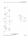
The SRL-250 uses a remote valve package
that can be mounted for customer
convenience. The valve package is
mounted to a 1/2" x 1 0" x 15-1 /2" plate for
ease of installation. The valve package
Advance Products Corporation
J
Page 3
SRL-250 USER'S MANUAL
j
A
o;•
'
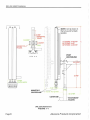
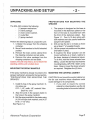
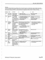
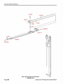
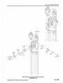
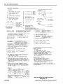
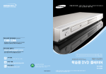
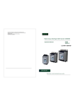
NOTE: Unit is shown in
the full up and full back
position.
A
6-5.8 REr
12" STROKE: A=39 3/16"
24" STROKE: A=52"
36" STROKE: A=63 3/16"
9/16REFTYP. 4
PLACES.
A
PIVOT
CENTERLINE
VIEW' A- A
3-3/16 REF
25REF
I
I
~
t
' 10 RE F
FJJli:h PLAT Et4WIDTH
o _ol
~O~O_(!!j O_(!!JJOf!l
j.:t RE I
I
1
I
I
I I
COVER DIE~
18-1/4 REF
~STATIONARY
~ PLATEN
SRL-250 Dimensions
FIGURE 1- 1
Page4
Advance Products Corporation
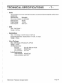
TECHNICAL SPECIFICATIONS
- 1-
Motor
AC brush less servo motor with high resolution encoded and electromagnetic spring-action
safety brake.
Manufacturer:
Mitsubishi
Servomotor Model: HC-MFS438
Rated Output:
400W
Rated Torque:
1.3 N-m
Rated Speed:
3000 rpm
Unit
Size: See Figure 1.
Weight: 240 Lbs.
Control Box
Size: 8-1 /2" deep x 15-3/4" wide x 19-3/4" tall
Power Requirements: Single-phase, 11 0 VAC, 15 amps
Weight: 45 Lbs.
Valve Package
Size: 8-3/4" deep x 10" wide x 15-1 /2" tall
Weight: 40 Lbs.
Air Requirements
Air Flow:
50 cubic feet per minute
Air Pressure:
50-to-90 psi.
Air connection: 3/4" NPT
Lube Requirements
Lube Pressure: 40-to-80 psi
Lube connection: 3/8" NPT
Advance Products Corporation
Page S
SRL-250 USER'S MANUAL
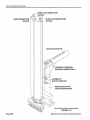
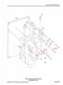
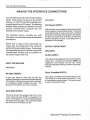
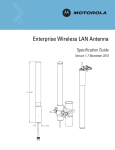
SHCS 3/8-16
x 1-1/2
3/8 COIL TYPE
LOCK WASHER
SPRAYER PLATEN
0-RING
118 THICK x 1-1/2 0.0.
SPRAY MANIFOLD
SRL-250 Manifold Attachment
FIGURE 1-2
Page6
Advance Products Corporation
UNPACKING AND SETUP
UNPACKING
The SRL-250 contains the following:
(1) sprayer mechanism.
(1) valve package
(1) main control cabinet.
( 1) Lube filter
(1) spray manifold.
Perform the following steps to unpack the unit:
1. Unfasten the sprayer from the shipping
container.
2. Move X-axis member to the full retracted
position
3. Remove the main control cabinet from
the shipping container and set aside.
4. Remove the valve package from the
shipping container and set aside.
Caution, the unit is top heavy, do not leave free
standing until the unit is bolted down
MOUNTING THE SPRAY MANIFOLD
If the spray manifold is already mounted to the
sprayer mechanism, proceed to the next section,
"PREPARATIONS FOR MOUNTING THE
SPRAYER."
1. Install 0-rings in the spray manifold. 0 ring sizes are:
0 .D.: 1-1 /2", width: 1/8", material: Viton
Dash No: -218
2. Align the ports in the sprayer platen to
the holes in the spray manifold.
3. Bolt the spray manifold to the platen using
(4) 3/8 coil type lock washers, and (4) 3/
8-16 x 1-1/2" shes.
See Figure 1-2.
Advance Products Corporation
- 2-
PREPARATIONS FOR MOUNTING THE
SPRAYER
1. The sprayer is designed so the base is
mounted on the stationary platen so the
front of the base is mounted flush with
the front of the stationary platen. See
Figure 1-1 . Four Y2-13 shes along with
lock washers are to be used to fasten the
sprayer to the platen.
2. Drill and tap the (4) Y2-13 holes so there
are at least 1" of useable threads.
3. Lift the sprayer into position on the platen
and fasten in place.
4. If required, the linear actuator can be
moved vertically up or down, relative to
the base, because of clearance issues.
To do this, hold the linear actuator from
falling . Loosen the (6) hhcs that hold the
mounting blocks, APC P/N: 10207, to the
base. Raise or lower the linear actuator
as required. Retighten the (6) hhcs.
MOUNTING THE CONTROL CABINET
CAUTION: Do not mount the control cabinet on
the die cast machine where vibrations could
cause damage to its components.
1. If you wish to mount the control
cabinet to a fixed location, use the (4)
mounting holes in the control cabinet.
Page 7
SRL-250 USER 'S MANUAL
CONNECTING THE AIR AND LUBE LINES
CONNECTING THE CABLES
{The standard SRL-250 sprayer is designed to
1. The motor control and encoder cables
rotate 90 degrees during a die change out. Make
have plug connectors at the motor.
your air and lube connections to allow for this
rotation.)
Connect these two cable.
2. The proximity switch cable needs to
1. Use a 1/2" I. D. hose or pipe to supply
be wired in to the junction box near
lube to the sprayer valve package.
Plumb the provided lube filter into the
the sprayer motor.
3. The valves need to be wired to the
lube line. The lube connection at the
control box. Holes are already
sprayer is 3/8 NPT. Be sure to flush
provided in the bottom of the control
the lube lines before connecting them
to the sprayer to keep contaminants
box and on the junction box on the
from entering the sprayer.
valve plate.
2. Use a 3/4" I. D. hose or pipe to supply
filtered air to the sprayer valve CONNECTINGTHEACPOWER
package. (Filter is not supplied.)
1. The sprayer is designed to run on 120
3. After mounting the valve plate at the
VAC, single phase, 15 amp service.
desired location, make up (1) spray
Connect power to through the
air hose, (1) blast air hose, and (1)
provided hole in the bottom of the
lube hose. Both the blast air hose and
the spray air hose need to have %
control cabinet.
FJIC fitting on both ends. The lube
hose needs to have 3/8 FJIC fitting
on both ends.
4. Connect the lube hose between the
lube valve and the sprayer
mechanism.
5. Connect the spray air hose between
the spray air valve, the valve with the
pressure regulator, and the sprayer
mechanism. See Figure 5-1 for the
correct connection point.
6. Connect the blast air hose between
the blast air valve and the sprayer
mechanism. See Figure 5-1 for the
correct connection point.
PageS
Advance Products Corporation
PROGRAMMING & SOFTWARE
-3-
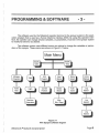
The software used by the Mitsubishi operator terminal in the sprayer system is the application program that is used as a Human Machine interface (HMI). By using this operator interface, the operator can change several variables, or parameters, involved in the sprayer system
to modify its behavior as desired.
The software system uses different menus as options to change the variables or parameters of the sprayer. These menus are shown in Figure 3-1 below:
Main Menu
Position
Machine
Parameters
Figure 3-1
APC Sprayer software diagram
Advance Products Corporation
Page9
SRL-250 USER'S MANUAL
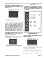
To change any program or machine parameter
of the sprayer system, use the operator panel
and its different sections on the keypad. A general procedure of how the operator interacts with
the sprayer system, via the operator panel, will
be explained below and before entering the software menus explanation.
INITIAL AND NORMAL RUNNING MENUS
Once the sprayer system is powered, pull the
red power button. The display will show the
startup screen shown in Figure 3-4.
El50 V6 . 03
FX- SERIES (CPU)
Power-up Screen Figure 3-2
To select a menu, it is necessary to use function
keys. Once selected, a menu for the corresponding screen will be displayed. The function keys
available on the sprayer system can be seen in
Figures 3-2 and 3-3.
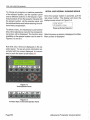
After the power-up screen is displayed, the Main
Menu screen is displayed.
Note that only 2 lines are displayed on the operator panel. To see any more information associated with the screen displayed, it is necessary to push the down arrow button.'f
0150
<MAIN MENU>
PROGRAM:AAAAAAAA
..
. .
.
HR~I!WliMJ&m
.
v
0
v
.
\......)
7
8
9
4
5
6
1
2
3
v
v
..
•
&
.......
\..._)
v
'@
Figure 3-2
E150 Operator Panel
Figure 3-3
Function keys on the E150 Operator Panel
Page 10
Advance Products Corporation
SRL-250 USER'S MANUAL
MAIN MENU
Key
Push#
This is the first screen as shown in Figure 3-4.
From this screen all other screens may be
reached.
Main Menu Figure 3-4
This screen shows the actual sprayer program
that is loaded into memory. The sprayer program
is identified by the "Program:' on the display,
followed by the program name. In the example,
the program name used is: AAAAAMA.
Push the down arrow button to see the lines
shown in reverse video in Figure 3-4. The date
is displayed in European Date Format in the
bottom left hand corner with the year listed first
followed by the month and then the day. In this
case, the year is 2003, the month is August and
the day is the 1st.
4
0
R
3
%
1
y
z
y
z
2
A
A b
a
3
<
>
(
'
@
2
5
#
-
.
)
6
7
!
?
a
0
1-
1-
8
9
-
I~
~
I~
-
11-
1-
4
M
N
0
p
m
n
0
p
5
Q
R
s
T
q
r
s
t
6
u
v w
X
u
v
w
X
-
+
*
=
7
A
I
8
c
D
a
b
c
d
8
E
F
G
H
e
f
g
h
9
I
J
K
L
i
j
k
I
AlphaNumeric Entry Table Figure 3-5
The time is displayed next to the date in the bottom line. To change the date, type the new entry over the old.
Note: See the table in Figure 3-5 for the dash
and colon entries. To display later push entries,
you must push the key again in quick succession. For example: Push the zero key once to
get 0. Push the zero key twice quickly to get the
R symbol. Push the zero key three times quickly
to get the % symbol. Push the zero key four
times quickly to get the #symbol. Push the zero
key five times quickly to get the : symbol.
To change the time, the date must first be reentered, then enter the time. Please note that
the time is 24 hour time. (No AM or PM.)
Push the enter key to complete your entry of
the date and time.
Advance Products Corporation
Page
11
SRL-250 USER 'S MANUAL
HOME
Performing a Home Sequence is required after
power is applied. This allows setting a zero reference position, relative to a programmed move
in a user program. The HOME/NEXT key is used
to perform a sprayer home sequence. After
touching the HOME/NEXT key, the following
screen appears.
Home Sprayer. PRESS
HOMECF6) To Start
Home Screen Figure 3-6
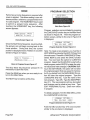
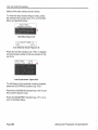
PROGRAM SELECTION
Main Menu Figure 3-8
Program selection can be initiated by pressing
the LOAD/SAVE function key on the Main Menu
as shown in Figure 3-8. Then the program selection screen, similar to the one in Figure 3-9
is displayed.
~--------------~
Once the Start Home Sequence key is touched,
the sprayer arm will begin moving back to the
home position. During that time, the current
position is displayed next to Position: in a screen
similar to Figure 3-7 below.
Home in Progress ...
Position:-7.12
Home in Progress Screen Figure 3-7
The Stop Move key should be pressed if it is
necessary to abort the move.
Press the MAIN key when you are ready toreturn to the Main Menu .
The NEXT key is inactive at this time.
__PROGRAM OPTIONS__
NEW DEL SAVE LOAD
Program Selection Screen Figure 3-9
Note: To create a new program, you must be in
EDIT MODE by pressing the EDIT (F2) key from
the main menu. Press the LOAD/SAVE (F5) key.
Select NEW by and press the SAVE function
key. You now have the option to CLEAR the
program . Select the CLEAR (F2) to start with a
clean program, select NO(F5) to retain the original values and make changes. CAUTION: Starting in the EDIT MODE, this option will not clear
the original program that was saved in memory,
but if you started from the MAIN MENU this option will clear the original program. Type the
LOAD/SAVE (F5) key. Type the name of the
new program. Type OK. Type the MAIN/PREV
key (F1 ). The new program will now be loaded
and changes can be made at any time. Type
EDIT PROGRAM (F2) key. Enter new values
in program.
To delete a program, from the Main Menu, press
the LOAD/SAVE function key.
__PROGRAM OPTIONS__
NEW DEL SAVE LOAD
Program Selection Screen Figure 3-11
Push the DEL function key <F3> and a screen
similar to the one below is displayed.
Page 12
Advance Products Corporation
SRL-250 USER'S MANUAL
PROGRAM EDIT
>ALL FILES
I_SELEC
I
Program editing may be initiated by pressing
EDIT/PROG function key on the Main Menu
the
DEL Program Selection Screen Figure 3-12
as shown in Figure 3-8. Then the program edit
Pressing the SELEC function key <F2> deletes screen, similar to the one in Figure 3-17, is disthe program displayed above the SELEC key. played.
In this case, ALL programs will be deleted.
l:P :OO.OO S:OO.OO
Push the down arrow T to see the complete list
D:OO.OL:OffA: Off P: N
of stored program files that can be deleted.
2:P:OO.OO
S:OO.OO
Press the EXIT function key <F5> to return to
D:OO.OL:OffA:Off P:N
the Program Selection Screen as shown in Figure 3-13.
EX IT
T
__PROGRAM OPTIONS__
NEW DEL SAVE LOAD
20:P:OO.OO S:OO.OO
D:OO.OL:OffA:Off P:N
Program Selection Screen Figure 3-13
Edit Program Screen Figure 3-17
Push the LOAD function key <F5> and the
screen shown in Figure 3-14 is displayed.
Each screen shows 21ines of program information at a time. Each program may contain up to
>zzll Y22I
20 program steps. After entering values tor
EXIT.
l. SELEC
Step 10, you must press the EDIT PROG key
LOAD Screen Figure 3-14
to reach step 11-20. Press the up arrow ~ and
Press the up arrow ~ and down arrow T keys down arrow T keys as shown in Figure 3-18 to
to cycle through the program names available. cycle through the program steps.
Press the SELEC function key <F2> to load the
program into memory. Press the EXIT function Press the left arrow ~ and right arrow ....,.... keys
key <F5> to return to the program selection as shown in Figure 3-18 to move between the
fields on the screen.
screen.
J
__PROGRAM OPTIONS__
NEW DEL SAVE LOAD
Program Selection Screen Figure3-15
Touch the MAl N/PREV function key <F1 >to return to the Main Menu shown in Figure 3-10 is
displayed.
Arrow Keys on the E150 Keypad Figure 3-18
The edit screen is displayed with the cursor on
the position field , ready tor keypad entry. Press
the desired numbers with or without a decimal
point. Press the <ENTER> key for the number
ram in memory.
to be placed in the current
Main Menu Figure 3-16
Enter Key on the E150 Keypad Figure 3-19
Advance Products Corporation
Page
13
SRL-250 USER'S MANUAL
If the number entered is too large or too small,
screens similar to the ones shown in Figure 320 are displayed and the cursor is returned to
the offending field .
JOG Functions
~--------------~
Val > Max 35
Val < MI N 0
Position Entry Error Screens Figure 3-20
0000 ~ 0
0000
0
0000
The speed and dwell values can be entered in
a similar fashion.
To toggle the Lube, Air and Part Detect, press
the <ENTER> key as shown in Figure 3-21 below.
Enter Key on the E150 Keypad Figure 3-21
Front Console Figure 3-23
To enter JOG mode, make sure that the mode
switch is pointed to MAN, as shown in Figure
3-23, which enables the JOG up and down
switch also shown in Figure 3-23.
To view the Jog Selection Screen (Figure 325) , press the JOG/AUTO function key <F4>
on th e Main Menu as depicted below.
<MAI N MENU>
PROGRAM: AAAAAAAA
_ PRESS MAIN(F1) FOR
_SYSTEM INFORMATION.
03-08-01 13:32: 13>
Main Menu Figure 3-24
_<< SE LECT MODE >>
JOG
AUTO
Jog Selection Screen Figure 3-25
Press the JOG function key <F2> to display a
Page 14
Advance Products Corporation
SRL-250 USER'S MANUAL
Jog Screen similar to the one shown in Figure
3-26.
rent position .
Pressing the SAVE function key <F5> stores the
current position in the current program step number.
Jog Screen Figure 3-26
Pressing the SPEED function key <F2> toggles
the speed between SLOW and FAST. Pressing
the SPRAY/LUBE function key <F4> causes lube
to be sprayed while the <F4> function key is depressed. Pressing the BLAST/AIR function key
<F5> causes air to be blown while the <F5>
function key is depressed.
Press the down arrow "f key to display the current position.
Press the HOME/NEXT function key <F6> to display a screen similar to the one shown in Figure
3-27.
STOP STEP : 01 MOVE w
MOV E INC DEC TO
T
Jog Screen Figure 3-27
Pressing the STOP MOVE function key <F2>
stops any move currently in progress. Pressing
the INC function key <F3> causes the step number to be incremented by one, up to step number 20. Pressing the DEC function key <F4>
causes the step number to be decremented
down one, but not below step number one.
Pressing the MOVE TO funct ion key <F5>
causes the sprayer to move to the position specified in the currently displayed step number.
Press the HOME/NEXT function key <F6> to display a screen similar to the one shown in Figure
3-28.
PRESS SAVECF5) TO
STORE IN STEP :01
Jog Screen Figure 3-28
Press the down arrow T key to display the cur-
Advance Products Corporation
Page 15
SRL-250 USER'S MANUAL
1/0 STATUS
These menus can be displayed by choosing the
<1/0 Status> function key <F3> on the Main
Menu shown in Figure 3-29.
Main Menu Figure 3-29
The first screen shown is the INPUTS screen
as shown in Figure 3-30. This screen shows
the status of the digital inputs to the sprayer system; for example, limit switches, push buttons
and some incoming signals from the customer.
INPUTS
SERVO ABSO :OFF :XO
SERVO ABSl :OFF : Xl
SERVO ABS3 :OFF : X2
SPARE
:OFF : X3
CYCLE START :OFF : X4
DI E OPEN
:OFF : X5
HOME SWITCH :OFF : X6
AUTO MODE :OFF : X7
SERVO READY:OFF : XlO
SPARE
:OFF : Xll
PART DETEC1 :0Fr : X12
JOG UP
:OFF : X13
JOG DOWN
:OFF:X14
SPARE
:OFF : Xl5
I NPUTS
STEP OUTPUT :OFF : YO
DIRECTION
:OFF:Yl
MOTOR BRAKE :ON :Y2
SPRAY LUBE :OFF:Y3
PART FAULT :OFF:Y4
AIR BLAST
:OFF :Y5
CYCLE COMPLT :OFF :Y6
DIE SAFE
:OFF :Y7
SERVO ABSl :OFF :YlO
SERVO ABS2 :OFF :Yl l
T
OUTPUTS Screen Figure 3-31
Touch the HOME/NEXT key to display the SYSTEM STATUS BITS screen shown in Figure 332.
_SYSTEM STATUS
STOP BIT Ml
JOG DOWN M61
JOG UP M62
START 1"10VE M8
STOP MOVE Ml02
IN CYCLE MllO
BITS_
:OFF
:OFF
:OFF
:OFF
:OFF
:OFF
SYTEM STATUS BITS Screen Figure 3-32
INPUTS Screen Figure 3-30
Touch the HOME/NEXT key to display the OUTPUTS screen shown in Figure 3-31 .
Page
16
Advance Products Corporation
SRL-250 USER'S MANUAL
MACHINE SETTINGS
(Caution!)
Press MAIN/PREV again and the following
screen will be displayed.
In this section there are several menus containing the main machine parameters. By changing
these parameters you can change the complete
behavior of the sprayer system. Great care must
be taken in chang ing any of these parameters.
These parameters should only be modified by
qualified technical personnel.
Login Required screen Figure 3-35
This section allows the user to change any of
the parameters on the sprayer system.
IMPORTANT: These parameters are set at
the factory and are critical for proper machine operation. Modifying these parameters
may cause machine damage and/or injury to
personnel operating the sprayer. Do not
make any changes to these settings without
a thorough understanding of each parameter
(refer to t he Main Default Parameters discussed on Page 18.)
To begin, press MAIN/PREV on the Main Menu
as depicted in Figure 3-33 below.
Before changing parameters, an authorization
code must be entered and recognized by the
system. Press HOME/NEXT function key <F6>
for entry of the password as shown in Figure 336.
I
Password:***
Password Entry screen Figure 3-36
Touch the 3 key, the 0 key and the 3 key. Touch
the enter key in the lower right hand corner.
The system will display the following screen
momentarily to indicate that the system is now
unlocked and Machine Setting modifications
are possible.
Level is 1
System Unlocked screen Figure 3-37
Figure 3-38 is then displayed.
Main Menu Figure 3-33
The System Information screen is then displayed as shown in Figure 3-34.
Login Required screen Figure 3-38
Press MAIN/PREV and the machine parameter
MODEL SRL-250
E- Term Rev: 101
FX PLC Rev: 101
Cycles:
: 37631678
For Assistance Ca l l
Advance Products
Ph:
269-849 -1000
Fax: 269-849 -2200
System Information screen Figure 3-34
Advance Products Corporation
Page
17
"'0
ll>
co
(/')
<D
::0
r-
~
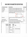
MACHINE PARAMETER DEFINITIONS
......
co
0
c::
gj
(/')
PLC Parameter Description
Parmeter Definition
Fast Jog Speed
10.0
The speed the arm moves when being jogged manually in slow mode.
5.0
The speed at wh ich the arm moves during a home sequence after power up. 3.0
The acceleration value in milliseconds used when the arm moves to ramp up 300
Default Values
The speed the arm moves when being jogged manually in fast mode.
Slow Jog Speed
Home Speed
Ace/ Dec
and down to the program speed.
Set
Velocity
Ace
(in
Q..
c::
()
(j)
(')
0
-a0
tti
~
0
:::s
I
Dec
Cycle Complete T ime
The time in seconds the cycle output will stay on.
::J
C3
I~
:~
I
Retract speed
ti5
1J
ms. ) ~
I
~ (in ms.)
-jl
The speed of the arm during a an emergency retract operation or end of
100
cycle.
~ Maximum Stroke in Inches
--Q.. 1
I Sprayer Type
()
Q)
L:
I
I
The maximum distance from home to the furthest spray position.
The sprayer type is set in the Sprayer Type Setting screen. For the MMI to
run the correct program, the ladler type must be accurate.
Servo Amp
Parmeter
Parameter# Definition
2
3
19
21
41
54
Default
Values
Pulse Per/Pis
0105
96
Unlock
OOOE
Pulse & Direction
300
0110
0001
Auto Tune
DIA
Motor Direction
Notes
Cycle Power After Setting
3.0
35.0
1
CJ)
~
~
§;:
r-
SRL-250 USER'S MANUAL
AUTO CYCLE
screen similar to the one below is shown . (The
following screen depicts the default Machine Parameter values.)
_MACH IN E PARAMETERS
I - - - - · -FAST JOG SPD· -----SLOW ,JOG SPD : 05
HOME SPEED :03
ACC/DEC
:0500
RETRACT SPD :100
CYCLE CMPLT :03.0
MAX POSITION:35 . 00
SPRAYER TYPE : 01
To enter Auto Cycle, make sure the mode switch
is pointed to AUTO as shown below in Figure 340. A customer supplied input is required to run
an AUTO CYCLE.
- - - -- -~- ------- --- -
@]
0000
0000
0000
~~
Machine Parameters screen Figure 3-39
To show different lines of Machine Parameters,
press the up arrow ~ and down arrow T keys
as shown in Figure 3-40. Press the left arrow
~ and right arrow ...,.._ keys as shown in Figure 3-40 to move between the fields on the
screen. Any entry may be changed by positioning the cursor over the desired field, enter a new
value and press the <ENTER> key to accept it.
If the selected value is out of range when entered, the parameter value will not be changed.
Of interest on this screen is the sprayer type.
For the MMI to run the correct program, the
sprayer type must be accurate.
To select a different sprayer type, just touch the
appropriate sprayer model number.
Arrow Keys on the E150 Keypad Figure 3-40
fiJ
\OJ
~
0
@]
Front Console Figure 3-40
While in Auto Cycle, a screen similar to the one
below is displayed.
POSIT ION:
13. 03
CYCLE TIME : 006 . 9
PARTS P/H : 521
TOTAL PARTS :OOOOOOOO
_PRESS LOAO(F5) TO
RESET PART COUNTER
LUBE OFF AIR OFF
Auto Cycle screen Figure 3-41
The Auto Cycle screen shows the cycle time,
Parts per hour, and total parts.
As the sprayer arm moves, the current arm position of the sprayer is updated in the Position field.
The Auto Cycle screen also shows the cu rrent
Advance Products Corporation
Page 19
SRL-250 USER 'S MANUAL
status of the lube valves and air valves.
To view the Auto Screen (Figure 3-25) , press
the JOG/AUTO function key <F4> on the Main
Menu as depicted below.
Main Menu Figure 3-42
_<< SELECT MODE >>
JOG
AUTO
Auto Selection Screen Figure 3-43
Press the AUTO function key <F5> to display
an Auto Screen similar to the one shown in Figure 3-44.
POSITION :
13 . 03
CYCLE TIME : 006 .9
PARTS P/H : 521
TOT/\L P/\RTS : 00000000
PRLSS LOAO( F5) TO
RESlT PART COUNTER
LUBF OfF AIR OfF
Auto Cycle screen Figure 3-44
To edit lines in the currently running program,
press the EDIT/ PROG function key <F2>.
Press the LOAD/SAVE function key <F5> to set
the counters back to zero.
Press the MAIN/PREV function key <F1 > toreturn to the Main Menu.
Page 20
Advance Products Corporation
-4-
TROUBLESHOOTING
This part of the Manual will help you locate and
correct difficulties that might occur in your
Reciprocating Die Spray System. The following
chart lists specific problems, and one or more
conditions that could cause each difficulty. Also
refer to the "Technical Documentation", section
6 of this Manual, for additional information
concerning pinout, jumper configurations,
schematics, etc. for each board or module
discussed in this section.
If you need to order parts, refer to the
"Replacement Parts" list on page 7-1 to obtain
descriptions for each part.
In an extreme case where you are unable to
resolve a difficulty, please contact Advance
Products and we will do all we can to help you
resolve the problem. Our address and telephone
number are located at the bottom of the front
page in this Manual, or by pressing the Help
keypad on the Operator's Panel.
IMPORTANT: If it becomes necessary to ship
any part of your Reciprocating Die Spray System
to Advance for repair, please make sure that
you include a thorough description of the
problem(s) you are having on your Return
Materials Authorization form received from
ADVANCE®.
CHART
PROBLEM
POSSIBLE CAUSE
SOLUTIONS
• Sprayer will not
power up.
• Disconnect switch not on .
• Missing 120 VAC power.
• E-Stop jumper missing or
customer interface is not
connected .
• Turn disconnect switch on .
• Check 120 VAC line fuses .
• Install jumper (see Elect.
Schematic Line 1.)
• Sprayer powers up,
but won't run in
Auto.
• Home sequence not
performed .
• Auto/Manual selector
switch not in Auto.
• No position entered in
MMI program.
• No cycle start received .
• Home sequence must be
performed after initial power
up.
• Turn selector switch to AUTO.
• Enter a position other than
zero.
Advance Products Corporation
Page 21
SRL-250 USER'S MANUAL
Chart (continued}
PROBLEM
POSSIBLE CAUSE
SOLUTIONS
• Sprayer won't do a
home sequence.
• Auto/Manual selector
• Turn selector switch to
switch not in manual or is
defective.
• Mechanical
linkage
bound up.
• Defective Servo Amp .
• Defective motor.
MANUAL.
• Check mechanical linkages
for binding .
• Check Servo Amp indicators
for faults.
• Replace Servo Amp if unable
to clear faults .
• Sprayer goes to
•
•
•
•
• Restore air pressure.
• Restore lube pressure .
spray positions, but
does not spray.
•
•
•
•
•
•
• Spray head constantly drizzles.
Page 22
No air pressure .
No lube pressure.
Low lube pressure .
Air or lube line is plugged.
Spray head is clogged.
Lube valve will not shift.
Air valve will not shift.
Spray head air pressure
too low.
Tank is out of lube .
Control not programmed
to spray.
• Adjust lube pressure.
• Remove obstruction .
• Clean spray head with a
•
•
•
•
•
solvent.
Check output/replace lube
valve.
Check output/replace air
valve.
Adjust air pressure .
Restore supply .
Check program .
• Foreign material under
• Disassemble and clean.
poppet assembly.
• Spring broken .
• Poppet assembly worn .
• Lube valve will not turn
off .
• Replace spring .
• Replace poppet assembly .
• Replace lube valve .
Advance Products Corporation
SRL-250 USER'S MANUAL
Chart (continued)
PROBLEM
POSSIBLE CAUSE
SOLUTIONS
• Inconsistent spray
mist.
• Spray head clogged
under poppet assembly.
• Spray head nozzle
clogged.
• Lube strainer plugged (on
the incoming line to
sprayer).
• Inadequate air supply.
• Tank is out of lube .
• Spray head needle is set
for too fine a spray .
• Inadequate air supply or
lube supply pressure.
• Clean spray head with a
solvent.
• Rinse Lube strainer (on the
incoming line to sprayer) .
• Increase air supply.
• Add lube to tank.
• Adjust spray head needle.
• Check for minimum pressure
fluctuation in air & lube .
• Sprayer retracts up
too far.
• Home Limit switch out of
adjustment .
• Defective Home Prox.
switch.
• Lower prox. switch bracket.
• Sprayer completes
cycle, but won't restart.
• Cycle Start signal did not
release.
• Verify Cycle Start signal and
interface relay. Cycle Start
is a momentary signal.
Advance Products Corporation
Page 23
SRL-250 USER'S MANUAL
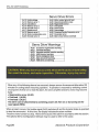
Servo Drive Errors
AL 10
AL12
AL13
AL15
AL 16
AL 17
AL 19
AL1A
AL20
Undervoltage
Memory error 1
Clock Error
Memory error 2
Encoder error 1
Board error 2
Memory error 3
Motor combination error
Encoder error 2
AL24
AL25
AL30
AL31
AL32
AL33
AL35
AL37
AL45
Motor output ground fault
Absolute position erase
Regenerative error
Overspeed
Overcurrent
Overvoltage
Command pulse frequency error
Parameter error
Main circuit device overheat
Servo Drive Warnings
ALEO
ALE1
ALE3
ALES
ALES
ALE9
ALEA
Excessive regenerative warning
Overload warning
Absolute position counter warning
ABS time-out warning
Servo emergency stop
Main circuit off warning
ABS servo on warning
CAUTION: When any alarm has occurred, eliminate its cause, ensure safety,
then reset the alarm, and restart operation. Otherwise, injury may occur.
When any of the following alarms has occurred, always remove its cause and allow about 30
minutes for cooling before resuming operation. If operation is resumed by switching control
circuit power off, then on to reset the alarm, the servo amplifier and servo motor may become
faulty.
• Regenerative error {AL30)
• Overload 1 {ALSO)
• Overload 2 {AL51)
The alarm can be deactivated by switching power off, then on or by turning on the
reset signal (RES).
When an alarm occurs, the trouble signal (ALM) switches off and the dynamic brake is operated
to stop the servomotor. At this time, the display indicates the alarm number.
The servo motor comes to a stop. Remove the cause of the alarm in accordance with this section.
The optional Servo Configuration Software may be used to refer to the cause.
Page 24
Advance Products Corporation
SRL-250 USER'S MANUAL
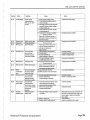
Display
AL10
Name
Undervoltage
Definition
Power supply
voltage dropped.
MR-J2S uA: 160V
or less.
Cause
1. Power supply voltage is low.
2. Power failed instantaneously for
15 ms or longer.
3. Shortage of power supply capacity
caused the power supply voltage
to drop at start, etc.
4. Power switched on within 5s after
it had switched off.
5. Faulty parts in the servo amplifier
.---- Checking method Alarm (AL10) occurs if power is
switched on after all connectors
Action
Inspect the power supply.
Change the servo amplifier.
I::IrA .
AL12
AL13
AL15
Memory error
Clock error
Memory error
AL16
Encoder error 1 Communication
error occurred
between encoder
and servo amplifier
RAM, memory faun
Printed board fau~
EEP-ROM fault
AL1 7
Board error 2
CPU/parts faun
AL19
Memory Error
ROM memory fautt
AL1A
Motor
combination
error
Encodererror2
Wrong combination
of servo amplifier
and servo motor.
Communication
error occurred
between encoder
and servo amplifier.
Ground Fau~
occurred at the
servo motor outputs
(U,V and W phases)
of the servo
amplifier.
Absolute position
data in error
Faulty parts in the servo amplifier
.---- Checking methodAlarm (any of AL12,13 and 15)
occurs if power is switched on
after all connectors are
disconnected.
1. CN2 connector disconnected.
2. Encoderfaun
3. Encoder cable faulty
0/Vire breakage or shorted)
4. Wrong combination of servo
amplifier and servo motor.
Faulty parts in the servo amplifier
.---- Checking method Alarm (AL17 orAL19) occurs if
power is switched on after all
Change the servo amplifier
Connect correctly.
Change the servo motor.
Repair or change cable.
Use correct combination.
Change the servo amplifier.
: ::~rP. .
AL20
AL24
AL25
Motor output
ground fault
Absolute
position erase
Wrong combination of servo
amplifier and servo motor connected.
Use correct combination.
1. Encoder connector disconnected.
2. Encoder cable faulty
0/Vire breakage or shorted)
Connect correctly.
Repair or change the cable.
1. Power input wires and servo motor
output wires are in contact at
main circuit terminal block (TE 1).
2. Servo motor power cable
insulation deteriorated.
Connect correctly.
1. Reduced voltage of super capacitor
in encoder.
After alarm has occurred, hold power on
for a few minutes, and switch it off once,
then on again. Make home position
return again.
Change battery.
Make home position return again.
2. Battery voltage low
3. Battery cable or batter is faulty.
Advance Products Corporation
Change the cable.
Page 25
SRL-250 USER'S MANUAL
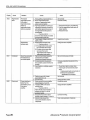
Display
AL30
Name
Regenerative
alarm
Definition
Permissible
regenerative power
of the buitt-in
regenerative brake
resistor or
regenerative brake
option is exceeded.
Regenerative
transistor fau~.
AL31
AL32
Overspeed
Overcurrent
Page 26
Speed has exceeded
the instantaneous
permissible speed.
Current that flew is
higher than the
permissible current
of the servo
amplifier.
Action
Cause
1. Wrong setting of parameter No. 0
2. Bui~-in regenerative brake
resister or regenerative brake
option is not connected.
3. High-duty operation or continuous
regenerative operation caused the
permissible regenerative power of
the regenerative brake option to
be exceeded.
Checking method
Show the status display and check
the regenerative load ratio.
4. Power supply vo~ge is abnormal.
260V or more.
5. Regenerative transistor tau~.
Checking method
1) The regenerative brake option
has overheated abnormally.
2) The alarm occurs even after
removal of the bui~-in
regenerative brake resistor or
reaenerative brake option.
1. Input command pulse frequency
exceeded the permissible
instantaneous speed frequency.
2. Small acceleration/deceleration
time constant caused overshoot to
be large.
3. Servo system is unstable causing
overshoot.
4. Electronic gear ratio is large
(parameters No.3, 4)
5. Encoderfaulty.
1. Short occurred in servo amplifier.
output phases U, V and W.
2. Transistor (I PM) of the servo
amplifier tau~.
Checking method
Alarm (AL32) occurs if power is
switched on after U,V and W
are disconnected.
3. Ground fault occurred in servo
amplifier output phases U, V and W.
4. External noise caused the
overcurrent detection circuit to
misoperate.
Set correctly.
Connect correctly.
1. Reduce the frequency of positioning.
2. Use the regenerative brake option of
larger capacity.
3. Reduce the load.
Inspect power supply.
Change the servo amplifier.
Set command pulses correctly.
Increase acceleration/deceleration time.
constant.
1. Re-set servo gain to proper value.
2. If servo gain cannot be set to proper
value:
1) Reduce load inertia moment ratio: or
2) Reexamine acceleration I
deceleration time constant.
Set correctly.
Change the servo motor.
Correct the wiring.
Change the servo amplifier.
Connect the wiring.
Take noise suppression measures.
Advance Products Corporation
SRL-250 USER'S MANUAL
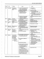
Display
AL33
AL35
AL37
Name
Overvoltage
Definition
Converter bus
voltage exceeded
400V.
Command
Input pulse
pulse frequency frequency of the
error
command pulse is
too high.
Parameter
Parameter setting is
error
wrong.
AL45
Main circuit
Main circuit device
device overheat overheat
AL46
Servo motor
overheat
Servo motor
temperature rise
actuated the
thermal protector.
AL50
Overload 1
Load exceeded
overload protection
characteristic of
servo amplifier.
Load ratio 300%:
2.5s or more
Load ratio 200%:
100s or more
Cause
1. Lead of built-in regenerative brake
resistor or regenerative brake
option is open or disconnected.
2. Regenerative transistor faulty.
3. Wire breakage of built-in
regenerative brake resistor or
regenerative brake option.
4. Capacity of buiH-in regenerative
brake resistor or regenerative
brake option is insufficient.
1. Pulse frequency of the command
pulse is too high.
2. Noise entered command pulses.
3. Command device failure.
1. Servo amplifier fault caused the
parameter setting to be rewritten.
2. Regenerative brake option not
used with servo amplifier was
selected in parameter No. 0.
1. Servo amplifier faulty.
2. The power supply was turned on
and off continuously by overloaded
status.
1. Ambient temperature of servo motor
is over 4QOC.
2. Servo motor is overloaded.
3. Thermal protector in encoder is faulty.
1. Servo amplifier is used in excess
of its continuous output current.
2. Servo system is unstable and
hunting.
3. Machine struck something.
4. Wrong connection of servo motor.
Servo amplifier's output terminals
U, V, W do not match servo
motor's input terminals U, V, W.
5. Encoder faulty.
Checking method
When the servo motor shaft is
rotated slowly with the servo off, the
cumulative feedback pulses should
vary in proportion to the rotary angle.
If the indication skips or returns
midwav. the encoder is faultv.
Advance Products Corporation
Action
1. Change lead
2. Connect correctly.
Change servo amplifier.
1. For wire breakage of built-in
regenerative brake resistor, change
servo amplifier.
2. For wire breakage of regenerative brake
option, change regenerative brake
option.
Add regenerative brake option or increase
capacity.
Change the command pulse frequency to a
proper value.
Take action against noise.
Change the command device.
Change the servo amplifier.
Set parameter No. 0 correctly.
Change the servo amplifier.
Review the drive method.
Review environment so that ambient
temperature is 0 to 400C.
1. Reduce load.
2. Review operation pattern.
3. Use servo motor that provides larger
output.
Change servo motor.
1. Reduce load.
2. Review operation pattern.
3. Use servo motor that provides larger
output.
1. Repeat acceleration/
deceleration to execute auto tuning.
2. Change auto tuning response setting.
3. Set auto tuning to OFF and make gain
adjustment manually.
1. Review operation pattern.
2. Install limit switches.
Connect correctly.
Change the servo motor.
Page 27
SRL-250 USER'S MANUAL
Display
AL51
AL52
Name
Over1oad2
Definition
Machine colision or
the like, caused max.
output current to
flow successively for
several seconds.
Servo motor locked:
1s or more
Error excessive Droop pulse value of
the deviation
counter exceeded
80kpulses.
Cause
Action
1. Machine struck something.
2. Wrong connection of servo motor.
Servo Amplifier's output terminals
U, V, W do not match servo
motor's input terminals U, V, W.
3. Servo system is unstable and hunting.
4. Encoder faulty.
Checking method
When the servo motor shaft is
rotated slowly with the servo off, the
cumulative feedback pulses should
vary in proportion to the rotary angle.
If the indication skips or returns
midwav. the encoder is faultv.
1. Acceleration/deceleration time constant
constant is too small.
2. Torque limit value (parameter No. 28)
is too small.
3. Motor cannot be started due to torque
shortage caused by power supply
drop.
4. Position control gain 1 (parameter No. 6)
value is small.
5. Servo motor shaft was rotated by
external force.
6. Machine struck something.
ALBA
Serial
RS-232 or RS-422
communication communication
time-out
stopped for longer
than the time set in
parameter No. 56.
ALBE
Serial
Serial communication
communication error occurred
between servo
amplifier and
communication device
(e.g. personal
computer).
8.8.8.8.1: Watchdog
CPU, parts faulty
Page 28
7. Encoderfaulty
8. Wrong connection of servo motor.
Servo amplifier's output terminals
U, V, W do not match servo motor's
input terminals U, V, W.
1. Communication cable breakage.
2. Communication cycle longer than
parameter No. 56 setting.
3. Wrong protocol.
1. Communication connector is
disconnected.
2. Communication cable fault.
(Open cable or short circuit)
3. Communication device (e.g. personal
computer) faulted
Fault of parts in servo amplifier.
Checking method
Alarm (8.8.8.8.8) occurs if power is
switched on after all connectors are
disconnected.
1. Review operation pattern.
2. Install limit switches.
Connect correctly.
1. Repeat acceleration/deceleration to
execute auto tuning.
2. Change auto tuning response setting.
3. Set auto tuning to OFF and make gain
adjustment manually.
Change the servo motor.
Increase the acceleration/deceleration
time constant.
Increase torque limit value.
1. Review the power supply capacity.
2. Use servo motor which provides larger
output.
Increase set value and adjust to ensure
proper operation.
1. When torque is limited, increase the
limit value.
2. Reduce load.
3. Use servo motor that provides larger
output.
1. Review operation pattern.
2. Install limit switches.
Change the servo motor.
Connect correctly.
Repair or change communication cable.
Set correct value in parameter.
Correct protocol.
Connect correctly.
Repair or change the cable.
Change the communication device (e.g.
personal computer).
Change servo amplifier
Advance P roducts Corporation
SRL-250 USER'S MANUAL
Warnings:
If ALE1 (overload warning) occurs, operation may be continued but an alarm may take place or proper operation may not be
performed. If another warning (ALE6 or ALE9) occurs, the servo smplifier will go into a servo-off status. Eliminate the cause of
the warning according to this section. Use the optional Servo Configuration software to refer to the cause of warning.
Display
Name
AL92
Open battery
cable waming
AL96
Zero setting
error
ALEO
Excessive
regenerative
waming
ALE1
ALE3
ALES
ALE6
ALE9
ALEA
Overload
warining
Absolute
position counter
waminQ
ABStime-out
waming
Servo
emergency stop
Main circuit off
waming
ABS
servo on
waming
Definition
Cause
Action
Absolute position
detection system
battery voltage is low.
1. In incremental
system: Zeroing
could not be made.
1. In absolute position
detection system: Zero
setting could not be
made.
There is a possibility
that regenerative powe
may exceed
permissible
regenerative power of
built-in regenerative
brake resistor or
regenerative brake
option.
There is a possibility
that overload alarm 1
or 2 may oocur.
Absolute position
encoder pulses faulty.
1. Noise entered the encoder.
2. Encoder faulty.
Take noise suppression measures.
Change servo motor.
-----------
1. PC !adler program wrong.
2. ST2 - TLC signal mis-wiring
Extemal emergency stop was made valid.
(EMG-SG opened.)
Contact APC for program correction.
Connect properly.
Ensure safety and deactivate emergency
stop.
Switch on main circuit power.
EMG-SG are open.
1. Battery cable is open.
2. Battery voltage dropped to 2.8V or less.
Repair cable or replace.
Change battery.
1. Droop pulses remaining are greater than
the in-position range setting.
2. Command pulse entered after the
clearing of droop pulses.
3. Creep speed high.
Remove the cause of droop pulse
occurance.
Do not enter command pulse after
clearing of droop pulses.
Reduce creep speed.
Regenerative p9wer increased to 85% or
more of permissible regenerative power of
built-in regenerative brake resistor or
regenerative brake option.
Checking method
e the status display and check
regenerative load ratio.
1. Reduce frequency of positioning.
2. Change regenerative brake option for the
one with larger capacity.
3. Reduce load.
Load increased to 85% or more of
overload alarm 1 or 2 oocurance level.
Cause, checking method ~
Refer to ALSO, AL51
E
r;;:
_er to
J
~L50 ~L5l
Servo was switched on
with main circuit
power off.
Servo on signal (SON) 1. PC ladder program wrong.
tumed on more than 1s 2. SON signal mis-wiring
after servo amplifier
had entered absolute
position data transfer
mode.
Advance Products Corporation
1. Contact APC for program correction.
2. Connect properly.
Page 29
SRL-250 USER'S MANUAL
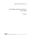
SPRAY AIR CONNECTION
3/
JIC
0
LUBE CONNECTION
3/8 MJIC
BLAST AIR CONNECTION
3/4 MJIC
ANTI-ROTATION PIN
LOOSEN TO POSITION
SPRAYER HORIZONTALLY
'"''-_,....,. LOOSEN TO
ROTATE SPRAYER
' - -REMOVE HITCH PIN
TO ROTATE SPRAYER
SRL-250 Position Adjustments
FIGURE 5-1
Page 30
Advance Products Corporation
MAINTENANCE AND
ADJUSTMENTS
SPRAYER POSITION ADJUSTMENTS
-5MAINTENANCE
The sprayer mechanism is not designed to be 30 days
removed from the base. The sprayer can be Fully extend the spray manifold into the die area.
rotated in the base to provide clearance during Turn the sprayer off to prevent accidental
a die change out. To rotate the sprayer, follow movement of the sprayer.
the below procedure:
1. Loosen the (2) %-13 SHCS in the Remove the front cover of the sprayer
front of the base.
mechanism. There are (3) %-20 bolts on the
2. Remove the 3/8 hitch pin from the top and bottom of the cover that hold the cover
base
in place.
3. Rotate the sprayer mechanism in the
base.
Wipe the 2 chromed inner telescoping tubes
clean with a clean cloth.
Repeat this procedure in reverse order to
reposition the sprayer in the correct position after Wipe the 3 chromed outer telescoping tubes
the new die has been installed.
clean with a clean cloth.
The horizontal distance between the spray
manifold and the base can also be adjusted.
1. Loosen the {2) %-13 shes on the
horizontal tube of the sprayer. There
is an anti rotation pin that will prevent
the unit from rotation when these
SHCS' are loosened.
2. Manually push the sprayer to the
desired position. Caution: DO NOT
push against the manifold or against
the chromed tubes when trying to
reposition the sprayer. This may
damage the sprayer.
3. Tighten the {2) %-13 shes to prevent
the sprayer from moving.
See Figure 3.
Check that all air and lube fittings are tight.
These fittings are located on the mechanism and
the valve plate located remote from the sprayer
mechanism. Tighten any lose fitting .
Inspect the lube hose for wear or damage.
Replace if it is damaged.
Check that the fittings that hold the outer
telescoping tube to the platen and the
mechanism are tight. Tighten any lose fitting.
Check that the (6) mounting blocks that hold the
linear actuator to the base are tight. Tighten
any lose blocks.
Wipe the motor and gearbox clean with a clean
cloth.
Replace the sprayer cover, power the unit up,
move the sprayer to the home position.
Advance Products Corporation
Page 31
SRL-250 USER'S MANUAL
90 days or 100,000 cycles
Fully extend the spray manifold into the die area.
Turn the sprayer off to prevent accidental
movement of the sprayer.
Remove the front cover of the sprayer
mechanism. There are (3) %-20 bolts on the
top and bottom of the cover that hold the cover
in place.
Lubricate the drive unit rails by the below
process.
1. At about half the stroke press and
manually move the belt in order to see
one of the two rails inside the unit,
2. Using a grease syringe or brush,
apply a conspicuous quantity of
grease on the raceways. Use a
lithium based grease of medium
consistency.
3. Repeat this procedure for the other
rail.
Replace the sprayer cover, power the unit up,
move the sprayer to the home position. Cycle
the unit up and down 5 - 10 times for the full
stroke of the unit at slow speed to distribute the
grease on the full length of the rails.
6 months
Remove and replace the lube filter with new.
This interval may change depending on your die
lube. Dirty lube can cause your spray head to
malfunction. Small contaminants in the lube can
prevent the poppet inside of the spray head from
sealing properly. This will cause the spray head
to leak. As these small contaminates build up
in the spray head, the spray head may become
plugged and no lube will pass through the spray
head.
Page 32
Advance Products Corporation
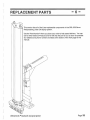
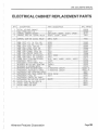
REPLACEMENT PARTS
-6-
This section lists all of the User-replaceable components in the SRL-250 Servo
Reciprocating Linear Die Spray system.
Use the "Part Number'' when you place your order to help speed delivery. You can
call or write Advance Products and we will ship the part to you as soon as possible.
Our address and phone number are listed at the bottom of the front page of this
manual.
Advance Products Corporation
Page 33
SRL-250 USER'S MANUAL
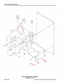
'-.---- - --1-- - - r 8707
1637
10309-1_.__------...1
SRL-250 Top Block Assembly
FIGURE 6-1
Page 34
Advance Products Corporation
SRL-250 USER'S MANUAL
10171
10172
10160
10164
10159-1
SRL-250 Slide Block Assembly
FIGURE 6-2
Advance Products Corporation
Page
35
SRL-250 USER'S MANUAL
0117..()44
10292-030
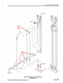
SRL-250 Vertical Unit Assembly
FIGURE 6-3
Page 36
Advance Products Corporation
SRL-250 USER'S MANUAL
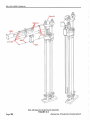
10161..........
-~~
~11
i
I
I
I
I
I
'
I
J
~~-
SRL-250 Vertical Unit Assembly 2
FIGURE 6-4
Advance Products Corporation
Page 37
SRL-250 USER'S MANUAL
SRL-250 Gearbox Attachmen t Assembly
FIGURE 6-5
Page 38
Advance Products Corporation
SRL -250 USER'S MANUAL
'" ''
10193
10295
.....
?
0117-006
SRL-250 Prox. Switch Bracket Assembly
FIGURE 6-6
Advance Products Corporation
Page
39
SRL-250 USER 'S MANUAL
0
10179
0121-032
SRL-250 Base Assembly
FIGURE 6-7
Page 40
Advance Products Corporation
SRL-250 USER'S MANUAL
4-1/2!' Approx. height
f
5289
0117-024
SRL-250 Mounting Vertical Unit to Base Assembly
FIGURE 6-8
Advance Products Corporation
Page 41
SRL-250 USER'S MANUAL
10173-XX
SRL-250 Cover Instal/a
FIGURE 6-9
Page 42
Advance Products Corporation
SRL-250 USER'S MANUAL
1637
SRL-250 Valve Plate Assembly
FIGURE 6-10A
Advance Products Corporation
Page 43
SRL-250 USER'S MANUAL
/
~'\
~0117-ooa
/
10307 &
10218
5289
SRL-250 Valve Plate Assembly
FIGURE 6-108
Page
44
Advance Products Corporation
TECHNICAL DOCUMENTATION
- 7-
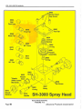
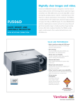
MODEL SH-3000
SPRAY HEAD
After years of research and development,
Advance, the industry leader in spraying technology, has developed the ultimate spray
head for die spraying. It is the Advance Model
SH-3000 spray head.
The Model SH-3000 has fewer parts and
an improved design over previous Advance
models. Adjustablility is greatly improved with
a full three-turn range compared to 1-1/2 on
the Model 2000. There is also improved atomization consistency over a larger variation
of air to lube pressure.
The Model SH-3000 offers a wide range
of spray patterns with 9 interchangeable
nozzles from ultra-fine mist to maximum output. Special nozzles are available that offer
consistent flow/lube rates at a given pressure
regardless of air pressure.
All internal parts are warranted for
1,000,000 cycles. The spray head body has a
10 year warranty.
Advance Products Corporation
Advance Model SH-3000 Spray Head
FIGURE 7-1
FEATURES
• Wide range of spray volumes from ultrafine mist to heavy dosing.
• Not dependent on the same air and lube
pressures. In fact, the independent air
and lube pressures can vary from 40 psi
to 110 psi without affecting each other.
• .5 GPM per each nozzle outlet.
• No leak construction GUARANTEED.
Advance's new positive shutoff doesn't
permit leaking.
• Either internal or external mix nozzle
outlets can be used on the same head.
An APC exclusive!
• All internal parts are warranted
for1 ,000,000 cycles against leakage.
Body warranted for 10 years.
Page 45
SRL-250 USER'S MANUAL
0692
Ball
Fan/Cone
Q
~
8948
~FineFan
8968
~
WideFan ~
8975
Oval
~ go•
8969
Cone
~
~
~
8977
~Cone
8980
~
90°Fan ~
8953
Nozzle
*Nozzle
Seat
(0692 Comes
Standard)
8970
Nozzle
Retainer
0-ring
Needle
SH-3000 Spray Head
Spray Head Assembly
FIGURE 7-2
Page 46
Advance Products Corporation
SRL-250 USER'S MANUAL
SH-3000 Extensions, Accessories
FIGURE 7-3
AVAILABLE HEADS AND TUBES
SERIES
SH-3000 (Dual Outlet
Opposed Side)
SH-3000DC (Dual Outlet
Cover Side)
SH-3000DE (Dual Outlet
Ejector Side)
Advance Products Corporation
TUBE SYLE I LENGTH
None* (SH-TUBE-000)
1/4" copper/2" (SH-TUBE-001)
1/4" copper/4" (SH-TUBE-002)
1/4" copper/6" (SH-TUBE-003)
1/2" alum. straight/2" (SH-TUBE-004)
1/2" alum. straight/4" (SH-TUBE-005)
1/2" alum. straight/6" (SH-TUBE-006)
1/2" alum. 90°/2" (SH-TUBE-007)
1/2" alum. 90°/4" (SH-TUBE-008)
1/2" alum. 90°/6" (SH-TUBE-009)
Page 47
SRL-250 USER'S MANUAL
ORA WING STANDARDS:
_j
4
RELAY NAMING COJINENTION WITH CONTACT
LOCATIONS
SYMBOLS:
AC
NOTE REFERENCE {SEE THIS SHEET)
=t
=t
COMMON CONNECTION {INTERNAL
TO LOGIC ASSEMBLY ONLY)
~>- PLUG
'¢>
-@-
'S' INDICATES RELAY SUPPRESSION
td'd
ARROW INDICATES FUNCTION
INCREASE (ALWAYS CLOCKWISE)
AUTO
~AN
I
1
8
I
I o---
~............___THIS UNE CONNECTED
~T·~o:N:~T~D IN MAN
I1
OX ............___ THIS UNE CONNECTED
TO "8" IN UAN,
MULnPLE POSITION SWITCHES
NOT CONNECTED IN AUTO
"X" SHOWS CLOSED STATE
·o• SHOWS OPEN STATE
Q
CABLE
(GROUNDED
ON ONE
END ONLY)
DC TWISTED PAIR
DC
DC TWISTED PAIR
CAN BE RUN WITH TAN WIRE
INSIDE CONTROL ENCLOSURE
p
{MNEUMONIC) RELAY NAME
SHIELDED
DC
~
=t
-o- TERMINAL BOARD CONNECTION
A
AC TWISTED PAIR
PULSE TRAIN TWISTED PAIR
'""~NO
~~
!:li:'oi~"[~gTON~
RR
I
.!lill.
BLUE WIRE fOR LOW VOLTAGE
(LESS THAN 50 V0C
UNSUPPRESSED INDUCTIVE LOAD)
!_j
.:!.]
MOUNTED ON CONTROL PANEL.
JUMPER ON TERMINAIL STRIP
~ MOUNTED ON DRIVE.
WARNING
_ THIS EQUIPMENT MAY BE AT LINE
VOLTAGE EVEN WHEN NOT IN OPERATION.
TO AVOID ELECTRIC SHOCK DISCONNECT.
!] WARNING -
'"MBER
~
LINE NUMBER
SHEET NUMBER
YELLOW WIRE IS USED WHEN A CONTACT
MAY BE USED IN AN EXTERNALLY POWERED CIRCUIT.
POWER MUST DISCONNECTED AT ITS SOURCE AS WELL AS THE DRIVE POWER.
ANY ADDITION OR DELETION TO THIS ENGINEERED CONTROL SYSTEM
WITHOUT WRITTEN AGREEMENT BY MITSUBISHI, IS THE
RESPONSIBILITY OF THE INSTALLING PERSONNEL.
MOUNTED ON DOOR.
LINE
SHEET NUMBER
~~]
1.!J
WARNING - ~~~T~~T wo~C~ ~~c~~~6~T is
OR INTERCONNECTION DIAGRAMS APPLY
MOUNTED ON CABINET.
NC CONTACT
662~ p24
TWISTED TRIPLE
GENERAL NOTE - ~~~YN~ifThA~~~~~~E 0~E~n~E~T~~~RED.
..£j
E_j
CONTACT
ENERGIZED.
12 1 REFER TO TRANSFORMER NAMEPLATE FOR
~ CONNECTIONS OF PRIMARY LEADS.
13 1
~
NEVER REMOVE OR INSERT ANY MODULE
TRANSFORMER IS CONNECTED TO
LINE VOLTAGE EVEN WHEN THE
A-C DISCONNECT IS OPEN.
1~
MOUNTED ON CONTROL PANEL.
~
MOUNTED ON REMOTE CONTROL
!J
12.J
1
~======~--_JO~RiJC~A~R~DJW~H~IL~E~TH~ElJP~O~W~EBR_I~S~O~N~.~----_j
WARNING -
STATIONS
MOUNTED ON OPERATOR CONSOLE
MOUNTED & WIRED. SUPPLIED BY CUSTOMER
_, 1 CONNECT A-C INPUT TO L 1, L2 AND L3 AS SHOWN. IF THE
..::..J PHASE SEQUENCE INDICATOR DOES NOT LIGHT, INTERCHANGE
~
L1 AND L3 CONNECTIONS.
GROUND DEVICE TO PANEL GROUND STUD/BUS BAR
~ REMOVE JUMPER IF ADDITIONAIL INTERLOCK IS ADDED.
SIGNAL CONDUIT
?._j
1. USE EITHER:
A. RIGID STEEL, OR
B. FLEXIBLE ARMORED STEEL CABLE
2. WILL CROSS NON - SIGNAL CONDUIT AT AN ANGLE OF
BETWEEN 45 DEGREES AND 90 DEGREES .
3. WILL NOT BE ROUTED THROUGH JUNCTION OR TERMINAL
BOXES THAT CONTAIN NON-SIGNAIL WIRING.
4. REFER TO THE ELECTRICAIL DIAGRAM WHEN SELECTING
CONDUIT. DO NOT ASSUME ALL SIGNAIL WIRE WILL BE
IN THE SAME CONDUIT.
SEPAIRATELY MOUNTED -
NOT SUPPLIED BY MITSUBISHI.
~ SEPARATELY MOUNTED - SUPPLIED BY MITSUBISHI.
.:_j
~
?_j
I~
SEPARATELY MOUNTED.
USE TWISTED TWO - CONDUCTOR CABLE. THIS CABLE MUST BE
IN A SEPARATE SIGNAIL CONDUIT. IT CANNOT BE RUN WITH
OTHER CONDUCTORS OR CABLES.
REFER TO TABLE 1 BELOW FOR WIRE SPECIFICATION DATA
SIGNAL WIRE
SIGNAL WIRE CABLES WITH THIS NOTE NUMBER CAN BE IN THE
SAME SEPARATE SIGNAL CONDUIT. THEY CANNOT BE RUN WITH
NON - SIGNAIL WIRES. FOR TWISTED TWO CONDUCTOR CABLES. USE
BELDEN PART NUMBER 9497 OR EQUIVALENT FOR TWISTED
THREE CONDUCTOR CABLES. REFER TO TABLE I BELOW FOR WIRE
SPECIFICATION DATA.
REFER TO NOTE 9. THE NUMBER FOLLOWING THE NOTE 9
IDENTIFIES THE CABLES THAT MAY BE GROUPED TOGETHER IN
THE SAME SIGNAL CONDUIT. FOR EXAMPLE, CABLES REFERENCED
WITH NOTE 10 CANNOT BE RUN IN THE SAME SIGNAL CONDUIT
WITH NOTE 9-2 CABLES.
(PREFERRED)
\. WILL BE NON-SHIELDED TWISTED CONDUCTOR.
2. WILL NOT BE RUN WITH NON-SIGNAL WIRE.
3. WI LL AILWAYS BE RUN IN STEEL CONDUIT.
4. WILL BE TWISTED TWO - OR THREE - CONDUCTOR CABLE.
SPECIFIC INSTRUCTIONS fOR EACH SIGNAL CABLE ARE
FOUND ON THE ELECTRICAL DIAGRAMS.
IF SHIELDED WIRE IS USED FOR SIGNAIL WIRE, THE GROUND/SHIELD
IS TO BE GROUNDED ON ONE END ONLY TO AVOID SIGNAL GROUND LOOPS
AND ERRATIC OPERATION.
TABLE 1
BELDEN
PART NO.
(SPEC. NO.)
9497
9498
TWISTS
N~~JluE~o% PE~~~T
TWO
TWISTED
THREE
TWISTED
NOMINAL
O.D.
24
{1/2")
0.2·
8
(1 1/2")
0.3"
COLOR
BLK & ORG
ORANGE
BLK, ORG, &
ORG WITH
BLK TRACER
BOTH HAVE THE FOLLOWING CHAIRACTERISTICS:
VOLTAGE RATING 600 VOLTS
AWG SIZE
STRANDING
- 19 X 29
INSULATION TEMPERATURE
(-} 40'C TO ( +) 1os·c
-
16
PVC
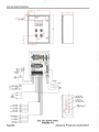
SRL-250 INSTALLATION Note Sheet
FIGURE 7-4
Page 48
Advance Products Corporation
SRL-250 USER 'S MANUAL
115V, 1PH
FROM
USER'S
PROTECTED
AC SUPPLY
APPROXIMATE
INPUT CURRENT
15A
L1
200
#14
2CB1
REO
201
2t.4CR1
201
10 A
289
289
#16
LQ
E__~P
200
210
L:l
202
203
203
2PB1
MAINTAINED
I
I
C>-<l...L.D---0
---
204
0
1A
s
'R
/
213
2CB7
2MCR1
289
2Pll
1203
211
'
~
212
200
TO SERVO AMP
SHT 5
[ 208 )
#14 WHT
6 RED
288
5049-04
2MCR1
289
wHT
EMERGENCY STOP
CONTACTOR
204, 211 , 320, 417
LQ
'
24V POWER SUPPLY
15W
289
L 85- 264VAC N o- f . - -
205
I
[ 208)
/
}
-<>t
r
=
PS5R-B24
v-
~+
2PS1
#18 BLU
I
256 (+)
24VDC TO
SHT 3, 4, 5
257 (-) }
3PC1
205
289
L 100-240V N o- I - -
r~+
200
---
2CB3
208
208
JA
4~R1
PLC POWER
INPUT
SHOWN ON
SHT 3
206
289
LUBE
206
289
AIR
207
289
AIR 8LAST
[ 41J)
208
4ABR1
I
/.2
[ 416)
SRL-250 1PH POWER DISTRIBUTION
FIGURE 7-5
Advance Products Corporation
Page 49
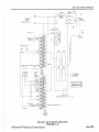
-----SRL-250 USER'S MANUAL
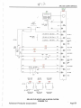
MAKING THE INTERFACE CONNECTIONS
You will need to provide some of the following
inputs. These inputs can be as a dry contact
closure, or a 120 VAC (24 VDC available upon
request) signal from a PLC output. The following
isolation relays supplied by Advance Products
provide normally-open contacts that are
prewired to the proper inputs.
The following section provides you with
information you will need to make the interface
connections.
NOTE: Due to noise on the control lines, we
require that all interfacing for the inputs be
switched through isolation relays. T-hese relays
are supplied by Advance Products and provide
normally-open contacts that are prewired to
the proper inputs to the PLC.
INPUT DEFINITIONS
Description
Die Open (3DOR1)
A user input signal on wires 322 and 323 that
enables the sprayerto move down in the die opening.
If this signal is missing during automatic operation,
an "emergency retract'' condition will occur. The
spray arm will retract to the "home" position.
Description
Part Sensor (3PSR1)
Optional input for part detection that can be added
by the customer on wires 324 and 325. If this input
is activated during an "auto cycle" and it is enabled
during the current step of the program, the sprayer
will stop any active move and return to the home
position and abort the cycle. A part detect error is
generated on the display.
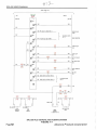
OUTPUT DEFINITIONS
Description
Die Safe (4DSR1)
This output will be enabled by the "home" proximity
switch input. Contacts from terminal 4DSR1 are
supplied on wire numbers 412 and 413. These
must be interlocked with the customers "die close"
circuitry.
Cycle Complete (4CCR1)
This output is enabled at the end of a Spray Cycle.
The contact is on wire numbers 410 and 411, and
is a momentary contact closure. This may be used
to start the Die Close Cycle.
Cycle Start (3CSR1)
This input will start the sprayer cycle if it is in the
"Auto" mode and relay 3CSR1 is energized. This
input is "anti-repeat'' so it must be released before
the sprayer will cycle again. The "cycle start'' signal
can be found on wires 320 and 321.
Advance Products Corporation
SRL-250 USER'S MANUAL
7032 - i 41
FXIN-241/T
DEVICE
30T1
I
1029 -17
.I
I
I
I
0 0 0 0 ~0
oooo. . 0
0000
.·
,I
,..
E150 ·.OIT
·• ~
/
205.
.\
24VDC
FROM SHT 2
.
l
..
115VAC FROM. · :.
SHT 2
J·
,-----A-,
257(-)
.;,~
@+
~
256 (+)
~N
289
257
256
I
DOl (CN16-4)
f18 BLU
300
TB20 TERM I
rz;sJ
I::!':'J
{
FROM SERVO
SHT 5
@COM
ZSP (CNI 8-1 9)
301
T820 TERM 19
TB20 TERM 2
TLC (CNIB-6}
xo
302
@XI
rr.:JX2
~
~X3
256
HOME
SWITCH
~
3CSRI
257
r--'-
3 WIRE
PROX
305
@X5
ABS BIT 1
SEND DATA
READY
SPARE
CYCLE START
OlE OPEN
( 326]
306
~
rz;sJ X4
I::!':'J
[ 326]
3DOR1
257
304
ABS BIT 0
306
MAN
I
257
I
I
s;-RI
257
LQ
_j_
I
257
fZiSl X6
I::!':'J '
AUTO
307
rr.:;,X7
ox
~
3SS2
308
[ 529 ]
I?.NX10
IS!2I
~XII
,.
3PSR1
257
JOG UP
-=t::=-1~ LQ
I
I
I
XOO
I
I
I
;1,:
I
I
257
257
I
I
SPARE
ON
PART SENSOR
311
@m
312
rr.:J X14
I::!':'J "
3SS1
#16 YEL
SERVO ALARM
RELAY
[ 326]
oox
I
AUTO
310
@XI2
JOG DOWN
HOME SWITCH
~X15
CYCLE START
RELAY 315
DIE OPEN
RELAY 316
PART SENSOR
RELAY 321
3CSRI
3DOR1
3PSR ~
JOG UP
JOG OOWN
SPARE
J! J! J!
320
321
322
323
d!I~O-:'j~
FOR END USER
CONNECTION
FOR END USER
CONNECTION
324
325
"----y-J
FOR END USER
CONNECTION
SRL-250 PLC INPUTS, 400 W SERVO SYSTEM
FIGURE 7-6
Advance Products Corporation
. Page 51
SRL-250 USER'S MANUAL
24VOC FROM SHT 2
7032- IAO
FXIN-241fl
257
256(+)
~
#16 BLU
I
#18
BL~
~24+
~COM
=
257
256
I
256
~couo
~
@YO
257
400 PP (CN1A-3) TB20 TERM 1
}
~COU1
~
@Y1
SERVO PULSE
TRAIN
401 NP (CN1A-2) T820 TERM 0
TO SERVO INPUTS
SHT 5
SERVO DIRECTION
IGil COU2
422
~
Y2
402
4BRI
YJ
403
4LR1
256
s
@
BRAKE RELAY
424
~Gil cow
~22
~
s
@
404
rr.;J Y4
=
@Y5
257
2UCRI 422
~22
4PDR1
s
405
4ABR1
406
4CCR I
s
256
LUBE RELAY
221
256
PART DET RELAY
414
256
AIR BLAST RELAY
225
256
CYCLE COMPLETE
425
256
DIE SAFE
425
_1ZEi1 COU4
~
[ 206 ]
@
Y6
~Y7
407
~
J;'NY10
s
40SRI
s
408 ABSM (CN18-8) TB20 TERM-3
~
Y11
@
409
ABSR (CN1B-9) T820 TERM-14
}
~
TO SERVO INPUTS
SHT 5
AFAN I
256
<8>
5AR1 421 48R1
~2~1 1)
4CCR1
r· ~jnc r·~-r m
410
411
412
413
r:J'i/~
T:l~
CYCLE
DIE
COMPLETE
CONTACT
,.
40SR1
SAFE
CONTACT
(+)
24VOC COM
257
414
~
BRAKE
CONTACT
TO MOTOR SHT 5
FAN
256
4PDRI
mr·~'"
415
YEL
416
~
PART DETECTEO
RELAY
SRL-250 PLC OUTPUTS, 400 W SERVO SYS TEM
FIGURE 7-7
Page 52
Advance Products Corporation
SRL-250 USER'S MANUAL
{~~=:~
TO BRAKE:
CONTROL
5SRV0 1
SHT 4
288
L l MR-J2S- 40AI
SERVO
~
AMPLIFIER
....::.;;_;_______-r-- - --+--o"
· 115VAC {
,FROM
SHT 2
APPROX. 9.7A
U
514
o-+--=--0~
--,,
v
o
'
\ .. J..
5 15
,'
',
~o-~-0----,, 5111 ;
0
w
289
---
516
/
L.!5
,
400W HP
170/60/3
J.2 1Ft (NEC)
,')... ,.,.,<..
:
:
'
)
'
....L.: ___ JI
288
a::
#18 BLU
289
L21
'-------+-0
.--~---,
FROM PLC {
OUTPUTS
SHT 4
Y1 401
J@IHP~ ~~o)
~
~~~2)
256
257
~~:
1 ~1 sc 4
t-:2~5~6_ _ _ _ _ _ _ _~25~5..+-::~::=:...j@
~~ia ~=~
ll.
Vl
N
~ ~
/
v
1/
1/
CNIB
r--
1/
1/
1/
1/
/
/
/CNJ
CN2
r--
CN1A
SET FOR
POSITION
-
/
-
~ LC
<(
556
~11:
-
'---~-~~;~~~~-H-@)
1 ~:
408
[ SERVO AMP SE TTINC
2
3
19
IIS2l' ~ 1l
~
(14)
~PISR
I
/
IS2J
535
IS2JRI:S i)
538
Al(ffA2( - ) 30 1
OOOE
0 110
u
r-------'
1@1~(15)
256
ATU
0 105
PULSES/P.U. PlS 64
tea- utrotoOQI)(
4 1 CIA
Ll@l~ ~J)
4 09
. __ _5:..:3..::.
5-1-l@
-}
TO PERSONAL
COMPUTER
NOT USED
-
(12)
L. .--+--1--+-1~·-m?.. . . j. .l ~l-~
~w.
#18 BLU
ENCODER
1/
1/
-
IN POSITION
~~~9)
IS2JSI) (9)
Vl
00
556~
5PG 1
v
CN 1A
r--
a::
u
......J 00
L.!5
TB20
-;::
'N 0
I
I
I
1/
~~
~
0
~~
'-'I=
~
1--
~~(17)
~
/
itl;)
c
l
~~~6
)
~llR
FROM PLC OUTPUT
SHT 4
(
lllt 1---...
~HGS(IS)
0 PLC INPUTS
SHT 3
}>
~
~~~J)
~
0 ~
g~
~Y0~40,_,0'--+_IS2!--J'~ PI'
~ ~ (11)
IS2JP~I)
FROM P.S. SHT 2
z~
GRN PLUG WITH
TERMINALS FOR L11, L21, P, C, D
COli
~@{16)
~LSP~~
~~~)
-IS2J'
lSP
SERVO ALARM RELAY 3 19
~@(19)
IS2JSI) (9)
T820
CNIB
SET FOR
POSITIONING
SRL-250 400 W SERVO AMPLIFIER
FIGURE 7-8
Advance Products Corporation
J
Page 53
SRL-250 USER 'S MANUAL
15.75
f---5.0 8 -
_t
-
I
.82
1-
u.
)<AMEPLATE
3X12
~r
TO END Of SCREE
NOT CUTOU
I
I
r==J
~
I
0000 ~0
0000
0000
v
~
19. 7
J .50
~!".~
I
.J7
L
0
~
l - - - s.1J -
115VAC
INPUT {
FROM
PROTECTED
SOURCE
EXT.
{
E-STOP
CIRCU IT
ENCODER
MOTOR
~
~
P'"'---?'Vr-::-'=-"'
BRAKE
WIRES
~ ~~~~----J
~
HOME
PROX
SWITCH
7/8.
CYCLE START
RELAY COIL INPUT
HOLES FOR 1/2 " NPT
SEALTIGHT FmiNG
OlE OPEN
RELAY COIL INPUT
PART SENSOR
RELAY COIL INPUT
CYCLE COMPLETE
RELAY OUTPUT
DIE SAFE
RELAY OUTPUT
PART DETECT
RELAY OUTPUT
Page 54
SRL-250 SERVO PANEL
FIGURE 7-9
Advance Products Corporation
SRL-250 USER'S MANUA L
ELECTRICAL CABINET REPLACEMENT PARTS
QTY
DESCRIPTION
PART DES IGNATION
APC PART#
1
1
5
3
RITTAL, AE1 045 CABINET
IDEC PS5R-B24 P.S.
OMRON, 0860YK SOCKET
OMRON, GR2-SN 120VAC RELAY
2PS1
4BR 1,5AR 1, 3DOR 1 3CSR1 , 3 PSR1
3DOR1, 3CSR1, 3PSR1
10559
10560
8019
7404
2
OM RON, G2R-SN 24VDC RELAY
4BR1, 5AR1
7405
1
1
1
1
1
1
1
3
3
5
1
1
1
1
1
ABB, S271-K1 , 1A 1PH, CB
ABB, S27 1-K3, 3A, 1PH , CB
ABB, S27 1-K10, l OA CB
ABB CBK-C3SK 3POS SW
ABB CB K -KLF8R RED P/L
ABB CBK-C2AMK 2POS SW
ABB CBK-PMP3R MSHD PB
ABB . CBK-CB1 0 NO CONTACT
ABB. CB K -C B01 NC CONTACT
FINDER, 38-51-7-024-0050 TB RELAY
GRAINGER, 4WT37 FAN
MITSUBISHI , FX1 N-24MT, PLC
MITSUBISHI, MR- J2S-40A1, SERVO AMP
MITSUBISHI, HC - MFS438K MOTOR
MITSUBISHI, MR 1B-5M MOTOR CABLE
MITSUBISHI JCCBL5M-H CABLE
MITSUBISHI MR-J2TB L05M CABLE
MITSUBISHI MR- TB20 SERVO TB
MITSUBISHI E150 OIT
MITSUBISHI, CAB 19-3M CAB LE
MITSUBISHI SN11AC120V RELAY
ALTECH CTS4U-N6 25A 600V TB
ALTECH 1056.2 GRD BLOCK
ALTECH CA802 END STOP
2CB2
2CB3
2CB1
3SS1
2PL 1
2SS2
2PB1
3SS1 3SS2
2PB1
4LR1 4AR1 4ABR1 4CCR1, 4SCR1
4FAN1
3PLC1
5SRV01
5M1
X INDICATES LENGTH
X INDICATES LENGTH
1
2
2
1
1
1
34
2
4
CN1A
301T 1
2MCR 1
CN1B
10562
105 63
10564
10565
10566
10567
10568
10569
10570
83 14
10558
10556
10555
10522
10520 - X
10521-X
9865
9866
10557
9873
10!:>o1
8839
8843
8803
I
J
Advance Products Corporation
Page 55
-
-
-
------- -·-·
SRL-250 USER 'S MANUAL
NOTES
Page 56
Advance Products Corporation
I
l
{
I
ADVANCE AUTOMATION EQUIPMENT
Digital Servo
Reciprocating
Sprayers
,. -r
Ole Casting Extractor
Trim Press
J
Shot Sleeves
Shot Sleeve Reworking
Plunger Tips/Rods
Fountain Water J u nriino•. fhermocouples
Hand Spray Guns
.,..
Slap Sticks
I
Tool-Temp
Temperature
Control Unit
Central Lube
Systems
Your "Window to the World"®of Die Casting Automation and Consumable Products
Phone: 269-849-1000
2527 HWY M-63, Benton Harbor, Ml 49022
Fax: 269-849-2200