1
ROBOT
SUPPLEMENT
Main System Software Version 2.3*
Copyright © DENSO WAVE INCORPORATED, 2005
All rights reserved. No part of this publication may be reproduced in any form or by any means without
permission in writing from the publisher.
All products and company names mentioned are trademarks or registered trademarks of their respective
holders.
Specifications are subject to change without prior notice.
Preface
DENSO WAVE has updated main system software designed for DENSO robot series from Version 2.2* to
Version 2.3*, with the introduction of **-G series (configured with RC7M controller).
This book is a supplement to the DENSO robot manuals. It describes newly added and updated functions.
Use this supplement together with other robot manuals.
For the following new products, refer to the related manuals as listed below.
(1) **-G series
"General Information About Robot" and "Installation & Maintenance Guide" for the
corresponding model
(2) RC7M controller
"Interface Manual for Denso Robot RC7M Controller"
(3) Options including teach pendant, mini-pendant, and extension boards
"Options Manual for Denso Robot RC7M Controller"
Contents
1
2
Newly added language selection window on TP top screen ............................................................................ 1
Free Curve Interpolation Control..................................................................................................................... 2
2.1 Overview........................................................................................................................................................ 2
2.2 Programming.................................................................................................................................................. 2
2.3 Free Curve Features ....................................................................................................................................... 4
2.4 Notes on Using Free Curve Interpolation....................................................................................................... 5
2.5 Addition of “Free Curve Interpolation” to Operation Command “MOVE”................................................... 6
MOVE (Statement) ...................................................................................................................................... 6
2.6 Commands and Libraries for Free Curve Interpolation.................................................................................. 8
SETSPLINEPOINT (statement)................................................................................................................... 8
CLRSPLINEPOINT (statement) .................................................................................................................. 9
GETSPLINEPOINT (statement) ................................................................................................................ 10
xdWAITSPLINE (library) .......................................................................................................................... 11
xdSPLPASSNUM (library) ........................................................................................................................ 12
xdSPLClrTakeArm (library)....................................................................................................................... 13
3 Reading and writing plural projects by USB flash memory ........................................................................... 14
3.1 Reading USB Memory Data into Robot Controller .................................................................................. 16
4
3.2 Writing Data Stored in Robot Controller into USB Flash Memory .......................................................... 19
Newly added operations by the mini-pendant ............................................................................................... 20
4.1 Performing CALSET ................................................................................................................................ 20
4.2
Resetting the motor encoder data .............................................................................................................. 21
4.3 Setting the calendar clock built in the robot controller (Date setting)......................................................... 22
4.4 Setting the next battery replacement date.................................................................................................. 23
5 Error Code Tables Modified ............................................................................................................................... 24
5.1 Error codes added or modified in version 2.3* (1)...................................................................................... 24
5.2
Error codes for the free curve interpolation added in version 2.3* (2) .................................................... 25
5.3
Error codes for the power supply board added in version 2.3* (3)......................................................... 26
Main System Software Version 2.3*
1 Newly added language selection window on TP top screen
The language selection window was added on the teach pendant top screen.
When turning the controller power on, use the teach pendant after selecting the
language (English or Japanese).
<Operation method>
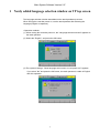
(1) When turning the controller power on, the “Language selection window” appears on
the teach pendant.
(2) Select the “English”, and press the OK button.
(3) The system message “ Show language select menu on next power on?” appears.
If you select “No” and press the OK button, the teach pendant is usable in English
after this operation.
1
Main System Software Version 2.3*
2 Free Curve Interpolation Control
Refer to the PROGRAMMER'S MANUAL (I), Section 3.3
"Interpolation Control."
Main system software version 2.3* supports the free curve interpolation control that is
useful in sealing, packing, and deburring.
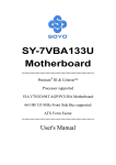
2.1 Overview
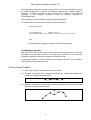
As shown below, the free curve interpolation control moves the robot tool tip on a free
curve passing through a series of specified viapoints at a constant speed. The tool tip
can accelerate to a constant speed and then decelerate to a stop at the end point.
This control provides stabilized robot motions in sealing, packing, and deburring.
Viapoints
Free Curve Interpolation Control
2.2 Programming
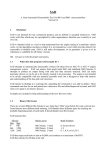
(1) Teaching viapoints
Use the teach pendant to teach viapoints with position (P) or joint (J) variables. Position
data taught with homogeneous transform matrix (T) variables requires conversion to
position variables using a T2P command in coding described in "(2) Registering
viapoints."
Create a correspondence table as shown below for clarifying the relationship between
viapoint numbers and position/joint variable numbers.
Motion start
point
Viapoints
Variables
Correspondence Table Sample for Viapoints and Variable Numbers
2
Main System Software Version 2.3*
(2) Registering viapoints
Specify the desired free curve trajectory number and register viapoints with
SETSPLINEPOINT commands. It is necessary to specify the trajectory number per
viapoint.
As shown in coding sample 1, create source code specifying viapoints in the order of
passing through. In this sample, the trajectory number is "1."
See the descriptions of SETSPLINEPOINT and CLRSPLINEPOINT commands for
details.
Coding sample 1: Registering Viapoints
(3) Executing free curve interpolation
Execute free curve interpolation with the free curve motion command "MOVE S
<Trajectory number>." Specification of viapoints should precede the free curve motion
command. See the description of MOVE.
When specifying viapoints immediately preceding the free curve motion command, write
code as shown in coding sample 2.
PROGRAM PRO1
TakeArm
.
.
.
CALL PASSPOINT1
MOVE S, 1
.
.
.
END
'Register viapoints
''Execute free curve motion of trajectory 1
Coding sample 2: Specifying Viapoints Immediately Preceding a
Free Curve Motion Command
3
Main System Software Version 2.3*
When specifying viapoints in programs other than free curve motion programs, execute
an xdSPLClrTakeArm(0) to prevent the specified viapoints from getting erased by
execution of TakeArm command in free curve motion programs. This is because
execution of the TakeArm command erases all viapoints specified by
SETSPLINEPOINT.
Coding sample 3 is an initialization program specifying viapoints.
For details, refer to the description of library xdSPLClrTakeArm.
PROGRAM INITIAL
.
.
.
CALL PASSPOINT 1
'Register viapoints
CALL xdSPLClrTakeArm(0) 'Make viapoint clearing by TakeArm invalid
.
.
.
END
Coding sample 3: Specifying Viapoints in Initialization Program
(4) Adjusting viapoints
Run the robot in Teach check mode to check the free-curved path move by using Halt,
Step Back, and Step Start functions. If the path move deviates from the ideal one,
interpolate viapoints to shorten the viapoint-to-viapoint intervals.
Increasing the speed may cause the path move to deviate inside the curve. To adjust it,
teach viapoints outside the ideal curve.
2.3 Free Curve Features
(1) Specifying a single viapoint produces a linear motion.
(2) Teaching four viapoints on a straight line produces a straight path between the
middle two viapoints as shown below.
(3) Modifying a viapoint(s) automatically modifies the path between the preceding and
following viapoints as shown below.
4
Main System Software Version 2.3*
(4) If the free-curved path move deviates from the ideal one, shorten the
viapoint-to-viapoint interval.
(5) Specifying such viapoints that produce reciprocating motions or sharp-angled
motions decreases the speed at the viapoints, triggering the "676* Jx command
accel limit over" or "60D0 Motion optimization function unexecutable" error. To
prevent occurrence of such errors, decrease the speed specified.
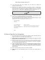
(6) To execute a non-motion command such as I/O setting in synchronization with a
motion, use an xdWAITSPLINE (library) as shown below.
The coding sample below sets I/O when the robot tool tip passes through P11 (4th
viapoint) on the free curve path given in Section 1.2, (1).
PROGRAM PRO1
TakeArm
.
.
.
CALL PASSPOINT 1
MOVE S, 1, NEXT
CALL xdWAITSPLINE (4,1)
SET IO[240]
.
.
.
END
'Register viapoints
'Execute free curve motion specified by trajectory 1
'Wait for the tool tip to pass through 4th viapoint
2.4 Notes on Using Free Curve Interpolation
(1) Up to 200 viapoints can be specified every trajectory number. Exceeding the limit
triggers the "685A Free curve pass point overflow" error.
(2) Up to 20 trajectory numbers can be specified. Exceeding the limit triggers the "685B
Number of free curve mismatch" error.
(3) Modifying viapoints after a free curve motion does not allow a Step Back operation
on the free curve path specified before the modification of viapoints, and triggers
the "737D Cannot step back further" error.
(4) If the move distance between viapoints is short and the posture change is great, the
"608* Jx command speed limit over" or "60D0 Motion optimization function
unexecutable" error may occur. To prevent occurrence of such errors, decrease the
speed specified.
(5) During conveyor tracking, no free curve motion is allowed.
(6) Under the free curve interpolation control, no recovery from power failure is
allowed.
5
Main System Software Version 2.3*
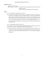
2.5 Addition of “Free Curve Interpolation” to Operation Command “MOVE”
Refer to the PROGRAMMER'S MANUAL (I), Section 12.1
"Operation Control MOVE."
MOVE (Statement)
Format
MOVE <Interpolation method>, [@<Pass start displacement>] <Pose> [<EX or EXA option>] [,
[@<Pass start displacement>] <Pose > <EX or EXA option>] ---] [, <Motion option>] [, NEXT]
[Ver. 2.3 or later]: Add the following.
For a free curve MOVE S, [@<Pass start displacement>] <Trajectory number> [<EX or EXA
option>] [, <Motion option>] [, NEXT]
Explanation
[Ver. 2.3 or later: Add S to the interpolation method.
Selection from four types, P, L, C and S, is possible as the <Interpolation method>.
Interpolation method
Meaning
P (or PTP)
The robot moves from the current position to the
designated coordinates using PTP control.
L
The robot moves from the current position to the
designated coordinates using CP control.
C
The robot moves to a purpose pose performing arc
interpolation via a relay point pose from the current
position.
The robot performs an interpolation motion from the
figure of the current position to that of the purpose pose
(the figure of the relay point pose is ignored).
In arc interpolation, a relay point pose and a purpose
pose must be designated.
(A pose array cannot be used for C.)
Even if pass start displacement is designated to a relay
point pose, the motion does not change.
Use MOVE C, P1, @P P2 to designate the pass taken
when the arc interpolation motion is finished.
S (Free curve)
[Ver.2.3 or later]
Moves from the current position to the final viapoint
through the registered viapoints by SETSPLINEPOINT.
The path becomes a smooth curve and the tool moves
at a constant speed on the path, except upon
acceleration/deceleration.
The pose passes each viapoint by pass movement.
<Trajectory number> is the trajectory number of the free curve and represents the free
curve viapoints registered by SETSPLINEPOINT for each <Axis Number> results. Up to
20 points can be designated.
6
Main System Software Version 2.3*
Example of use
Addition to [Ver.2.3 or later]
MOVE S, @P 2, S=10, NEXT ‘Pass operation at an internal speed of 10% for a free curve with
‘Trajectory number 2.
‘The next command is executed after the operation starts.
Notes
[Ver. 2.3 or later] Note 3: Including free curve motion
(3) In CP motion, arc interpolation motion and free curve interpolation motion, if the robot passes
in the vicinity of a singular point (refer to “Setting-up Guide, 4.1.3 Figures of the Shoulder,
Elbow, and Wrist, [2] Boundaries of Robot Figures”), an error with a level of 6080 (Command
speed limit over) will occur and the robot may stop. In this case, reduce the speed or set 2 or
3 in the optimal load capacity setting mode ((refer to “PROGRAMMER’S MANUAL (I), 4.6
Control Sets of Motion Optimization”). If the error still occurs, avoid the path in the vicinity of
the singular point.
[Ver. 2.3 or later] Addition of Notes (11) and (12).
(11) If the figure at the viapoint registered by SETSPLINEPOINT differs greatly from the current
figure in free curve motion, error 607F (Robot posture mismatch) results.
(12) If the figure change is great because of short moving distance between viapoints in free
curve motion, an error at a level of 6080 (designated speed limit over) may occur and motion
may stop. In this case, either slow down the speed or set 2 or 3 in optimal load capacity
setting mode.
7
Main System Software Version 2.3*
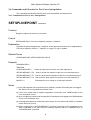
2.6 Commands and Libraries for Free Curve Interpolation
The commands and libraries used for free curve interpolation are shown below.
2.6.1 Commands for Free Curve Interpolation
SETSPLINEPOINT (statement)
Function
Registers viapoints in the free curve motion.
Format
SETSPLINEPOINT <Free curve trajectory number> <Viapoint>
Explanation
Registers the points designated by <Viapoint> as the viapoints of the free curve designated by <
Free curve trajectory number>. < Viapoint> is a type P or type J variable.
Related Terms
CLRSPLINEPOINT, GETSPLINEPOINT, MOVE
Example
PROGRAM PRO1
TAKEARM
CLRSPLINEPOINT 5
‘Clears all viapoints for the free curve with trajectory 5.
SETSPLINEPOINT 5, P4 ‘Sets P4 as the first viapoint for the free curve with trajectory 5.
SETSPLINEPOINT 5, P1 ‘Sets P1 as the second viapoint for the free curve with trajectory 5.
SETSPLINEPOINT 5, J5 ‘Sets J5 as the third viapoint for the free curve with trajectory 5.
MOVE S, 5
‘Executes free curve motion to J5 through P4 and P1.
Notes
(1) Up to 200 viapoints can be specified every trajectory number. Exceeding the limit triggers
the "685A Free curve pass point overflow" error.
(2) If free curve motion with no viapoint registration is executed, error “685B Number of free
curve mismatch” occurs.
(3) Up to 20 trajectory numbers can be specified. Exceeding the limit triggers the "685B Number
of free curve mismatch" error.
(4) If a designated viapoint is outside the motion range, an error at the level of 6070 (J* software
motion limit over) occurs.
(5) Before executing the “SETSPLINEPOINT” command, change the tool coordinates or the
work coordinates to the same ones as teaching viapoints, with the “CHANGETOOL” or
“CHANGEWORK” command.
8
Main System Software Version 2.3*
CLRSPLINEPOINT (statement)
Function
Clears all viapoints for free curve motion.
Format
CLRSPLINEPOINT <Free curve trajectory number>
Explanation
Clears all viapoints registered by SETSPLINEPOINT for the free curve trajectory designated by
<Free curve trajectory number>.
Related Terms
SETSPLINEPOINT, GETSPLINEPOINT
Example
PROGRAM PRO1
TAKEARM
CLRSPLINEPOINT 5
‘Clears all viapoints for the free curve with trajectory 5.
SETSPLINEPOINT 5, P4 ‘Sets P4 as the first viapoint for the free curve with trajectory 5.
SETSPLINEPOINT 5, P1 ‘Sets P1 as the second viapoint for the free curve with trajectory 5.
SETSPLINEPOINT 5, J5
‘Sets J5 as the third viapoint for the free curve with trajectory 5.
MOVE S, 5
‘Executes free curve motion via P4 and P1 to J5.
Notes
Executing CLRSPLINEPOINT results in non-registration of viapoints. Execution of free curve
motion without viapoint registration results in error “685B Number of free curve mismatch”.
9
Main System Software Version 2.3*
GETSPLINEPOINT (statement)
Function
Gets the viapoints for a registered free curve motion.
Format
<Approach point> = GETSPLINEPOINT (<Free curve trajectory number>, <Viapoint number>)
Explanation
Outputs each viapoint designated by <Viapoint number> for the free curve designated by <Free
curve trajectory number> to the <Viapoint>. The <Viapoint> is a type P variable.
Related items
CLRSPLINEPOINT, SETSPLINEPOINT
Example
PROGRAM PRO1
TAKEARM
CLRSPLINEPOINT 5
‘Clears all viapoints for the free curve with trajectory 5.
SETSPLINEPOINT 5, P4 ‘Sets P4 as the first viapoint for the free curve with trajectory 5.
SETSPLINEPOINT 5, P1 ‘Sets P1 as the second viapoint for the free curve with trajectory 5.
SETSPLINEPOINT 5, J5
‘Sets J5 as the third viapoint for the free curve with trajectory 5.
P10=GETSPLINEPOINT(5,2) ‘Sets the second viapoint for the free curve with trajectory 5 as
‘P10. (The data for P1 is set as P10.)
Notes
Designating an unregistered viapoint results in error “685C Number of free curve pass point
mismatch”.
10
Main System Software Version 2.3*
2.6.2 Libraries for Free Curve Interpolation
xdWAITSPLINE (library)
Function
Waits for the free curve to pass the designated viapoint.
Format
xdWAITSPLINE (<Viapoint number>, <Waiting condition>)
Explanation
Free curve motion in progress waits until passage on the point designated by the <Viapoint
number>.
If 0 is designated as the <Waiting condition>, the robot waits until the command value passes
the designated viapoint.
If a different value is specified, the robot waits until the encoder value passes the designated
viapoint.
Related Terms
MOVE, SETSPLINEPOINT
Example
PROGRAM PRO1
TAKEARM
CLRSPLINEPOINT 5
‘Clears all viapoints for the free curve with path No. 5.
SETSPLINEPOINT 5, P4
‘Sets P4 as the first viapoint for the free curve with trajectory 5.
SETSPLINEPOINT 5, P1
‘Sets P1 as the second viapoint for the free curve with trajectory 5.
SETSPLINEPOINT 5, J5
‘Sets J5 as the third viapoint for the free curve with trajectory 5.
MOVE S, 5, NEXT
‘Executes free curve motion to J5 through P4 and P1.
CALL xdWAITSPLINE(1,1)
SET IO[240]
‘Waits until the robot passes the first viapoint (P4).
‘Sets port 240 to ON.
CALL xdWAITSPLINE(2,1)
‘Waits until the robot passes the second viapoint (P1).
RESET IO[240]
‘Sets port 240 to OFF.
Notes
When xdWAITSPLINE is called with the free curve not executed, the robot does not wait.
Also, if xdWAITSPLINE is called after passing the viapoint designated by the <Viapoint number>,
the robot does not wait.
11
Main System Software Version 2.3*
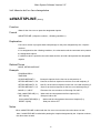
xdSPLPASSNUM (library)
Function
Obtains the viapoint through which the free line has passed.
Format
xdSPLPASSNUM (<Viapoint number>)
Explanation
For free curve motion in progress, the robot sets the viapoint number through which the
command value has passed to the <Viapoint number>.
Related Terms
MOVE, SETSPLINEPOINT
Example
PROGRAM PRO1
TAKEARM
CLRSPLINEPOINT 5
‘Clears all viapoints for the free curve with trajectory 5.
SETSPLINEPOINT 5, P4
‘Sets P4 as the first viapoint for the free curve with trajectory 5.
SETSPLINEPOINT 5, P1
‘Sets P1 as the second viapoint for the free curve with trajectory 5.
SETSPLINEPOINT 5, J5
‘Sets J5 as the third viapoint for the free curve with trajectory 5.
MOVE S, 5, NEXT
‘Executes free curve motion to move to J5 through P4 and P1.
DELAY 500
CALL xdSPLPASSNUM(I1)
‘Sets the passed viapoint number to I1.
12
Main System Software Version 2.3*
xdSPLClrTakeArm (library)
Function
Changes the validity of free curve viapoint clear process execution during TakeArm.
Format
xdSPLClrTakeArm (<Set value>)
Explanation
If the <Set value> is 0, the viapoint of the free curve during TakeArm is not cleared.
If the <Set value> is a different value, the viapoints of the free curve during TakeArm are
cleared.
Related Terms
CLRSPLINEPOINT、SETSPLINEPOINT
Example
PROGRAM INITIAL
CLRSPLINEPOINT 5
‘Clears all viapoints for the free curve with trajectory 5.
SETSPLINEPOINT 5, P4
‘Sets P4 as the first viapoint for the free curve with trajectory 5.
SETSPLINEPOINT 5, P1
‘Sets P1 as the second viapoint for the free curve with trajectory 5.
SETSPLINEPOINT 5, J5
‘Sets J5 as the third viapoint for the free curve with trajectory 5.
CALL xdSPLClrTaleArm (0) ‘Does not clear the viapoints of the free curve during TakeArm.
Notes
In the initial state after controller power on, free curve viapoints are cleared during TakeArm. To
register the free curve notion viapoints other than by the free curve motion program (for registration
by the intialization program), set by CALL xdSPLClrTakeArm(0) so as not to clear the viapoints for the
free curve during Take Arm.
13
Main System Software Version 2.3*
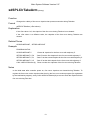
3 Reading and writing plural projects by USB flash memory
Refer to the “SETTING-UP MANUAL, Chapter 5”.
The robot controller RC7M supports to read/write plural projects using the USB flash
memory. The following USB flash memories are available to the controller.
Manufacturer
Model
EDP-###M, EDC-###M
I-O DATA
LMC-###UDA
Logitec
Note: (1) ### denotes the capacity.
(2) When formatting the USB flash memory, select tne “FAT” in the file system
menu.
(3) Never touch or remove a USB flash memory drive or turn the controller power
off when the USB flash memory drive is being accessed. (For details about
the USB flash memory access status, refer to the memory's user's manual.)
14
Main System Software Version 2.3*
Data that can be handled by USB flash memory drive
The table below lists data that can be handled by USB flash memory drives. Select the
appropriate data to read or write as necessary.
Data Type
File or Data
Source program
data
Source program files (PAC, H, PNL)
Executable files (NIC, MAP)
Settings files (DAT)
Only files with their compile
flags active ("Enable" in the
Use column) can be written
into USB flash memory.
All global data
Number of variables used
Reading variables data into
the robot controller
automatically changes the
"number of variables used" in
the controller.
Variables data
I/O data
I/O settings
Settings for expansion board
Arm parameters
Tool/work/area coordinates
definition
• Never read in arm data
prepared for other robots.
Visual equipment settings
Write (to USB flash memory)
only.
Arm data
Visual-related
data
Remarks
Log data
Communications settings
Version information
Various log data
Backup data
Various data
• Tool and work data
modified by TOOL or
WORK command will not
be updated when written
into the memory. To write
updated data, first save the
system parameters (see
the SETTING-UP
MANUAL, p. 5-179) and
then write data into the
USB flash memory.
Version 2.3 or later
Data exchange between robot controller and WINCAPSII
Data can be exchanged between the robot controller and WINCAPSII by means of a
USB flash memory drive.
For the operating procedures in WINCAPSII, refer to WINCAPSII Guide, Chapter 4,
Sections 4.3.4 and 4.3.5.
USB memory data modification not allowed
Never modify data stored in the USB flash memory drive from the robot controller. Any
modification makes it impossible to access the memory because USB memory data
contains check codes used for checking data corruption and guaranteeing accurate data
read/write.
15
Main System Software Version 2.3*
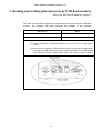
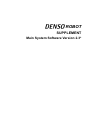
3.1 Reading USB Memory Data into Robot Controller
Access: [F6 Set]—[F3 USB Memory]—[F1 Read.]
Reads data stored in a USB flash memory into the robot controller.
(1) Press [F3 USB Memory] in the Setting (Main window), and the USB Memory Access
Menu appears as shown below.
F1
F2
(2) Press [F1 Read.] in the USB Memory Access Menu, and plural projects stored in a
USB flash memory appear as shown below.
Select data to read from the USB flash memory and then press the OK button.
16
Main System Software Version 2.3*
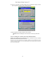
(3) The “Select File to Read” window appears as shown below.
Select data to read from the USB flash memory and then press the OK button.
Caution: Never read in arm data prepared for other robots. Doing so will
cause the robot to malfunction. It is very DANGEROUS.
(4) System message “ CALSET, RANG will be update. Are you sure?” appears.
17
Main System Software Version 2.3*
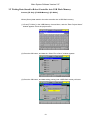
(5) Press the OK button, and data reading from the USB flash memory will start.
Upon completion of reading, system message appears.
(6) Upon completion of reading, restart the robot controller.
Caution: Without restarting the robot controller, the robot may malfunction.
Notes on reading new variables data from USB flash memory
Reading new variables from the USB flash memory overwrites the current variables
stored in the robot controller with the new ones.
Note that, if the robot controller has 50 integer variables and the USB flash memory
contains 30 integer variables, the 31st to 50th variables in the controller will be lost at the
end of the read operation.
18
Main System Software Version 2.3*
3.2 Writing Data Stored in Robot Controller into USB Flash Memory
Access: [F6 Set]—[F3 USB Memory]—[F2 Write.]
Writes (Saves) data stored in the robot controller into a USB flash memory.
(1) Press [F2 Write.] in the USB Memory Access Menu, and the “Enter Project Name”
window appears. Enter the project name.
(2) Press the OK button, and data the “Select File to Save” window appears.
(3) Press the OK button, and data writing (saving) into a USB flash memory will start.
19
Main System Software Version 2.3*
4 Newly added operations by the mini-pendant
Refer to the “SETTING-UP MANUAL, Chapter 6”.
You can operate the following items by the mini-pendant from Ver.2.3 or later.
(1) Performing CALSET
(2) Resetting the motor encoder data
(3) Setting the calendar clock built in the robot controller (Date setting)
(4) Setting the next battery replacement date
4.1 Performing CALSET
Access: [AUX key]—[ArmAux]—[CalSet.]
(1) The “ Select Joint “ screen for CALSET will appear as shown below.
M
VM XY
WOT 0
100
Select Joint
0
[Cancel / OK]
[Cancel / OK]
(2) Select the target joint for CALSET.
Note: If selecting “0”, the all-axis CALSET will be performed.
(3) If pressing the OK key, the CALSET will be executed.
TIP: For details about the CALSET procedure, refer to the INSTALLATION &
MAINTENANCE GUIDE, Chapter 4, "CALSET."
20
Main System Software Version 2.3*
4.2 Resetting the motor encoder data
( Only for the encoder model connected via bus Ex.: –G siries robot )
Access: [AUX key]—[ArmAux]—[EncRst]
You need to reset encoders and perform CALSET if:
-Error 641* occurs due to run-down encoder backup batteries, or
-Error 677* occurs due to a great impact applied to the robot when the power is off.
(* is any of 1 to 6 denoting the object axis.)
(1) The “ Select Joint “ screen for the encoder resetting will appear as shown below.
M
VM XY
WOT 0
100
Select Joint
0
[Cancel / OK]
[Cancel / OK]
(2) Select the target joint for the encoder resetting
(3) If pressing the OK key, the encoder resetting will be executed.
21
Main System Software Version 2.3*
4.3 Setting the calendar clock built in the robot controller (Date setting)
Access: [AUX key]—[Maintenance]—[Date]
Sets the calendar clock built in the robot controller.
(1) The “ Date –Display & setting “ screen will appear as shown below.
M
VM XY
WOT 0
100
Date
・Display
・Setting
[Cancel / OK]
(2) If selecting “Display”, the “Date” screen will appear as shown below.
M
VM XY
WOT 0
100
Date
2005/ 3/ 14
16h 21m 24s
[OK]
(3) If selecting “Setting”, the “Date Set” screen will appear as shown below.
M
VM XY
WOT 0
100
DateSet
2005/ 3/ 14
16h 21m 24s
[Cancel/OK]
(4) Choose an input field with the right and left cursor keys, then enter a new value with
the numeric keypad. If pressing the OK key, the date will be set.
22
Main System Software Version 2.3*
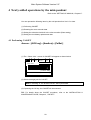
4.4 Setting the next battery replacement date
Access: [Aux key]—[Maintenance]—[Battery]
Sets the next replacement date of the memory backup battery of the robot controller.
When the replacement day comes, an error 2103 (level 1) - " Time to change controller
backup battery " will occur.
(1) The next “Battery Replacement“ date screen will appear as shown below.
VM XY
M
WOT 0
100
Battery
2005/ 3/
14
[Cancel/OK]
(2) Choose an input field with the right and left cursor keys, then enter a new value with
the numeric keypad. If pressing the OK key, the date will be set.
Note:
For the battery replacement procedure, refer to the “INSTALLATION &
MAINTENANCE GUIDE”.
23
Main System Software Version 2.3*
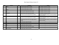
5 Error Code Tables Modified
Refer to the ERROR CODE TABLES.
The table below lists the error codes that are modified in Ver. 2.3 or later.
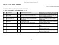
5.1 Error codes added or modified in version 2.3* (1)
Code
202E
Message
Mini I/O data error
Level
5
Description
Data error from the mini I/O occurred.
202F
Controller specifications error
4
The robot type does not match the controller type.
602A
Motor on failure
2
Communication timeout occurred and failed motor on.
602B
Motor on failure
2
Communication data error occurred and failed motor on.
602C
PWR communication error1
1
602D
PWR communication error 2
1
6101
Watchdog error
5
6140
Motor brake fuse blown
4
Power communication timeout occurred and stopped to
execute a process.
Power communication data error occurred and stopped to
execute a process.
(1) Interrupt process stopped.
(2) Power supply CPU stopped.(Only for RC7M)
(1) The motor brake fuse was blown.
(2) The contactor was failed (Only for RC7M).
660A
Safety board communication error
(ESC)
5
Safety board communication error detected.
660B
Safety board communication error
(BOX)
5
Safety box communication error detected.
24
Remedy
Check that there is no noise source (e.g., welding machine)
near the robot unit or controller. And restart the controller.
Make a suitable combination of the robot unit and controller.
And restart the controller.
If the error persists after turning the motor on again, you
need to investigate or repair the controller.
If the error persists after turning the motor on again, you
need to investigate or repair the controller.
If the error occurs frequentry, you need to investigate or
repair the controller.
If the error occurs frequentry, you need to investigate or
repair the controller.
If the error persists after rebooting the controller, you need
to investigate or repair the controller.
Check the motor-encoder cable.
Check the motor.
(3) You need to investigate or repair the contactor (Only for
RC7M).
(1) Check the connections between the I/O board and
peripheral devices.
(2) Check that there is no noise source (e.g., welding
machine) near the robot controller.
(1) Check the connections between the I/O board and
peripheral devices.
(2) Check that there is no noise source (e.g., welding
machine) near the robot controller.
Main System Software Version 2.3*
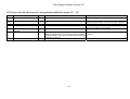
5.2 Error codes for the free curve interpolation added in version 2.3* (2)
Code
6858
Message
Free curve calculation error
6859
Free curve exec. condition error
685A
685B
685C
Level
3
Description
Free curve calculation error occurred.
Remedy
Check that via points are adequate or not.
3
Free curve motion can not be executed,
Free curve pass point overflow
Number of free curve mismatch
3
3
Exceeding 200 viapoints were specified in free curve.
Free curve trajectory number is mismatched.
3
The viapoint number is mismatch.
685D
Number of free curve pass point
mismatch
Free curve step back error
Check the executable conditions.
During conveyor tracking, no free curve motion is allowed.
Reduce viapoints up to 200.
Check the trajectory number of free curve.
Specify the viapoints if not specified.
Check the viapoint number of free curve.
3
685E
Free curve path deviation error
3
Step back error is occurred in the free curve.
Modifying viapoints after a free curve motion does not allow a
Step Back operation on the free curve path specified before the
modification of viapoints.
Path deviation is too much.
25
After execution of the free curve motion, execute Step Back
operation.
Check that via points are adequate or not.
Main System Software Version 2.3*
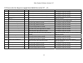
5.3 Error codes for the power supply board added in version 2.3* (3)
Code
230D
Message
Power supply start error
Level
5
Description
230E
Power supply A watchdog error
5
A watchdog error occurred in the power supply A.
230F
Power supply B watchdog error
5
A watchdog error occurred in the power supply B.
240D
4
Power supply communication failed.
2C07
Power supply communication
time-out
Interruption power detected
5
Interruption power detected in the AC power supply.
2C09
DC-BUS over voltage
5
2C0A
DC-BUS under voltage
5
2C0C
DC-output over voltage
5
2C0E
IPM module over voltage
5
2C0F
IPM module under voltage
5
2C2B
Regenerative-resistor overheated
5
2C2E
11VH over voltage
5
2C2F
11VH under voltage
5
2C30
Power board overheated (A)
5
The DC-BUS voltage exceeded the permissible upper value in
the power supply inside the controller.
The DC-BUS voltage exceeded the permissible lower value in
the power supply inside the controller.
The DC-output voltage exceeded the permissible upper value
in the power supply inside the controller.
The voltage to the IPM module exceeded the permissible
upper value in the power supply inside the controller.
The voltage to the IPM module exceeded the permissible lower
value in the power supply inside the controller.
The temperature of regenerated-resistor exceeded the
permissible upper value in the power supply inside the
controller.
The voltage of 11V-line exceeded the permissible upper value
in the power supply inside the controller.
The voltage of 11V-line exceeded the permissible lower value
in the power supply inside the controller.
The temperature of board (A) exceeded the permissible upper
value in the power supply inside the controller.
2C50
DC5V of power board over voltage
5
2C51
DC5V of power board under voltage
5
2C52
DC12V of power board over voltage
5
Power supply start failed.
The voltage of 5V-line exceeded the permissible upper value in
the power supply inside the controller.
The voltage of 5V-line exceeded the permissible lower value in
the power supply inside the controller.
The voltage of 12V-line exceeded the permissible upper value
in the power supply inside the controller.
26
Remedy
If the error persists after rebooting the controller, you need
to investigate or repair the controller.
If the error persists after rebooting the controller, you need
to investigate or repair the controller.
If the error persists after rebooting the controller, you need
to investigate or repair the controller.
If the error occurs frequentry, you need to investigate or
repair the controller.
(1) Check the connection of the AC power supply cable.
(2) Check the AC power supply voltage.
If the error persists after rebooting the controller, you need
to investigate or repair the controller.
If the error persists after rebooting the controller, you need
to investigate or repair the controller.
If the error persists after rebooting the controller, you need
to investigate or repair the controller.
If the error persists after rebooting the controller, you need
to investigate or repair the controller.
If the error persists after rebooting the controller, you need
to investigate or repair the controller.
Check the filter clogged or low rotation of the fan.
If the error persists after checking, you need to investigate or
repair the controller.
If the error persists after rebooting the controller, you need
to investigate or repair the controller.
If the error persists after rebooting the controller, you need
to investigate or repair the controller.
If the error persists after rebooting the controller, you need
to investigate or repair the controller.
Main System Software Version 2.3*
Code
2C53
Message
DC12V of power board under
voltage
DC24V of power board over voltage
Level
5
5
2C80
DC24V of power board under
voltage
DC24V of power board over voltage
(IO)
DC24V of power board under
voltage (IO)
Power board overheated (B-1)
Code
2C81
Message
Power board overheated (B-2)
2C82
IPM harness board overheated (B)
5
2CA1
Caution: Power board overheated
(A)
Cooling fan error
Caution: Fan speed dropped
Caution: Power board overheated
(B-1)
Caution:IPM Board overheated
1
Lamp disconnection
Caution:Power board
overheated(B-2)
2
1
2C54
2C55
2C56
2C57
2CB0
2CB1
2CB2
2CB3
2CB4
2CB5
5
5
5
5
Level
5
2
1
1
1
Description
The voltage of 12V-line exceeded the permissible lower value
in the power supply inside the controller.
The voltage of 24V-line exceeded the permissible upper value
in the power supply inside the controller.
The voltage of 24V-line exceeded the permissible lower value
in the power supply inside the controller.
The voltage of 24V-(I/O)-line exceeded the permissible upper
value in the power supply inside the controller.
The voltage of 24V-(I/O)-line exceeded the permissible lower
value in the power supply inside the controller.
The temperature of board (B-1) exceeded the permissible
upper value in the power supply inside the controller.
Description
The temperature of board (B-2) exceeded the permissible
upper value in the power supply inside the controller.
The temperature of IPM harness board (B) exceeded the
permissible upper value in the power supply inside the
controller.
The temperature of board (A) exceeded the warning value in
the power supply inside the controller.
The coolling fan stop detected inside the controller.
The low rotation of cooling fan detected inside the controller.
The temperature of board (B-1) exceeded the warning value in
the power supply inside the controller.
The temperature of IPM harness board exceeded the warning
value in the power supply inside the controller.
Disconnection of the motor-on detected lampe.
The temperature of board (B-2) exceeded the warning value in
the power supply inside the controller.
27
Remedy
If the error persists after rebooting the controller, you need
to investigate or repair the controller.
If the error persists after rebooting the controller, you need
to investigate or repair the controller.
If the error persists after rebooting the controller, you need
to investigate or repair the controller.
If the error persists after rebooting the controller, you need
to investigate or repair the controller.
If the error persists after rebooting the controller, you need
to investigate or repair the controller.
Check the filter clogged or low rotation of the fan.
If the error persists after checking, you need to investigate or
repair the controller.
Remedy
Check the filter clogged or low rotation of the fan.
If the error persists after checking, you need to investigate or
repair the controller.
Check the filter clogged or low rotation of the fan.
If the error persists after checking, you need to investigate or
repair the controller.
Check the filter clogged and cooling fan.
Check the cooling fan.
Check the cooling fan.
Check the filter clogged and cooling fan.
Check the filter clogged and cooling fan.
Check the wiring or connection.
Check the filter clogged and cooling fan.
SUPPLEMENT
Main System Software Version 2.3*
First Edition
July 2005
DENSO WAVE INCORPORATED
7G
The purpose of this manual is to provide accurate information in the handling and operating of the
robot. Please feel free to send your comments regarding any errors or omissions you may have
found, or any suggestions you may have for generally improving the manual.
In no event will DENSO WAVE INCORPORATED be liable for any direct or indirect damages
resulting from the application of the information in this manual.