1
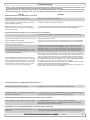
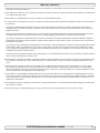
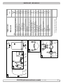
SE 30/125 S Ignition Protected thruster assembly SIDE-POWER Thruster Systems is rd th a p bo ee n K al o u an m ! SLEIPNER MOTOR AS P.O. Box 519 N-1612 Fredrikstad Norway Tel: +47 69 30 00 60 Fax: +47 69 30 00 70 w w w. s i d e - p o w e r. c o m s i d e p o w e r @ s l e i p n e r. n o Made in Norway Installation and user manual © Sleipner Motor AS version 1.- 201 Contents Contents specifications ......................................................... 2 Technical Planning & specifications.............................................................. important precautions ......................................... 32 Technical Stern thruster installation considerations ............................. 33 Planning & important precautions.............................................. Bolt on installation .................................................................. Stern thruster installation considerations...................................43 Mould on installation installation..................................................................... ............................................................... 54 Bolt on Gearhouse and motorbracket ................................................ 65 Mould on installation .................................................................. OilGearhouse tank & propellers .............................................................. and motorbracket. ....................................................76 Electromotor IP assembly ...................................................... 87 Oil tank & propellers.................................................................. Electrical installation ............................................................... Electromotor IP assembly. ..........................................................98 Control panel and control-leads .......................................... 109 Electrical installation .................................................................. Visual wiring ........................................................... 11 Control paneldiagram and control-leads............................................... 10 Visual wiring diagram............................................................... 11 Technical wiring diagram ..................................................... 12 Technical wiring diagram ......................................................... 12 Electrical installation of stern thruster systems ................... 12 Electrical............................................................................... installation of stern thruster systems ........................12 Checklist 13 Checklist................................................................................... 13 Important user precautions .................................................. 14 Important precautions. ...................................................... 14 How to use user Sidepower thrusters ......................................... 15 How to use .......................................................................... Sidepower thrusters..............................................16 15 Maintenance Maintenance............................................................................. 16 Troubleshooting .................................................................... 17 Troubleshooting. ....................................................................... 17 Warranty statement ............................................................... 18 Warranty statement .................................................................19 18 Parts list ................................................................................ Parts list. . .................................................................................. 19 Service centres ...................................................................... 20 Service centres ........................................................................ 20 DECLARATION OF CONFORMITY DECLARATION OFASCONFORMITY We, Sleipner Motor Box Motor 519 AS We, P.O. Sleipner Norway N-1612 P.O. BoxFredrikstad, 519 declare that thisFredrikstad, product withNorway accompanying N-1612 standard remote complies with the declare that this control productsystems with accompanying standardhealth remote control complies with the essential and safetysystems requirements according essential health 89/336/EEC and safety requirements according to the Directive of 23 May 1989 to the Directive 89/336/EEC of 23 May 1989 amended by 92/31/EEC and 93/68/EEC. amended by 92/31/EEC and 93/68/EEC. Technical specifications Technical specifications Motor: Motor: Gearhouse: Gearhouse: Custom made reversible DC-motor. Custom made reversible DC-motor. Seawater resistant bronze. Ballbearing at propellershaft; combination of ballbearing and slide bearing at Seawater resistant bronze. Ballbearing at propellershaft; combination of ballbearing and slide bearing at driveshaft. driveshaft. Motor bracket: Seawaterresistant aluminium. Motor bracket: Seawaterresistant aluminium. Ignition protection: Conforms to ISO 8846 Ignition protection: Conforms to ISO 8846 Propeller: Symmetrical 4 blade kaplan propeller, fibreglass reinforced composite. Propeller: 5-blade Skew-back design "Q-prop" propeller, reinforced composite. Batteries: Minimum recommended battery capacity (cold crank capacity by DIN standard) Batteries: Minimum recommended battery capacity (cold crank capacity by DIN standard) SP 30 Si IP 12V : 200 CCA DIN / 380 CCA SAE SE30/125S-12V : 200 CCA DIN/380 CCA SAE Max. use: Max. use: Safety: Safety: S2 electromotors are are protected protected against against overheating. overheating. S2==33min. min.ororappr. appr.7-10% 7-10% within within aa limited limited time time frame. frame. All All electromotors Electronic protectsagainst againstsudden sudden change of drive direction. Electric thermal Electronictime-lapse time-lapse device device protects change of drive direction. Electric thermal cut-offcut-off switch in switch in electromotor protects against over heating (auto electro reset when motor cools down). electromotor protects against over heating (auto reset when motorelectro cools down). Shearpin anddriveshaft driveshaftprotects protects electromotor gearsystem if propeller gets Shearpinbetween between electro-motor electro-motor and electromotor andand gearsystem if propeller gets jammed. jammed. If original Sidepower panel is used, the panel shuts off automatically 6 minutes after last use. If original Sidepower panel is used, the panel shuts off automatically 6 minutes after last use. Integrated microprocessor monitors solenoids, reducing wear and risk of solenoid lock-in. Auto-stop of thruster in Integrated microprocessor monitors solenoids, reducing wear and risk of solenoid lock-in. Auto-stop of thruster in case of accidental solenoid lock-in or if run signal is continous for more than 3 minutes. case of accidental solenoid lock-in or if run signal is continous for more than 3 minutes. Measurements ref. mm / inch A B C D E F G H Inside tunnel dia. Max. stern thickness Motor output Voltage W.L. SE30/125S SP30 S2iIPIP B 200mm /7.87" 190mm / 7.48" 135mm / 5.31" 197mm / 7.76" ø217mm / 8.54" ø160mm / 6.30" 6x ø6.5mm / 0.26" ø98mm / 3.86" 125mm / 4.92" C D 60° 14mm / 0.55" 1.5 KW / 2 HP 12 Volt Bolt holes dia: G Bolt position radius: H Cut out in stern: F A Outside of flange: E SE 30/125S ignition protected thruster assembly 1.01.- 2007 - 201 SP30S2i ignition protected thruster assembly 22 Planning and important precautions Prior to installation, it is important that the installer reads this guide to ensure necessary acquaintance with this product. The electromotor assembly must be handled carefully. Do not put it down on the driveshaft. Beware to keep installation within advised measurements. We advice to paint the gearhouse and propellers with antifouling. PS! Do not paint the zinc anodes, sealings or propellershafts. Do not finish the inside of the tunnel with a layer of gelcoat / topcoat or similiar. It is only room for a thin layer of primer and two layers of anti-fouling between the tunnel and the props. With the boat on land, only run the thruster for a fraction of a second, as without resistance it will accelerate very fast to a damaging rpm. Also, while the thruster is in air, make sure to avoid direction changes while the thruster is still running, as it might cause damage to the thruster. This manual is intended to support educated / experienced staff and is therefore not sufficient in all details for the correct installation. The thruster IP assembly has been tested to be fully ignition protected so that it can be installed in an area with the possibility of explosive gases in accordance to ISO 8846. Do not install the thruster in a position where you need to cut a stiffener/stringer/support for the hull integrity without checking with the boatbuilder that this can be safely done. When installed in boats approved or classified according to international or special national rules, the installer is responsible for following the demands in accordance with these regulations / classification rules. The instructions in this guide can not be guaranteed to comply with all different regulations / classification rules. NB ! Faulty installation of the tunnel, thruster or panel will render all warranty given by Sleipner Motor AS void. Stern thruster installation considerations To achieve maximum effect, reliability and durability from your Sidepower stern thruster, a correct installation is very important. Please follow the instructions carefully, and make sure that all checkpoints are carefully controlled. Additional considerations for positioning of the stern thruster Make sure that the stern-tunnel does not disturb the waterflow under the hull Ensure that when installed the thruster does not foul existing equipment inside the boat like steerage links etc. Make sure that the water flow from the thruster are not interfered too much by sterndrives, trimtabs etc. as this will reduce the thrust considerably. It is possible to mount the tunnel off the boat’s centre line if necessary. If the stern thickness is to much for the thruster in question you can easily remove hull material in the necessary area to fit the thruster. You only have to reduce the stern thickness down to the max. thickness measurement in the drawing. SE 30/125S ignition protected thruster assembly 1. - 201 3 Fig. 1 SEALANT Fig. 2 WASHERS LOCKNUT OR DOUBLE NUTS SEALANT Bolt on installation of the stern tunnel 1. Make sure that there are enough space both inside and outside the transom of the boat. 2. Once the place for the installation has been decided, hold the tunnel in place in the horizontal position and mark the bolt holes. Remove the tunnel and it is then possible to calculate and mark the centre. 3. It is important that the tunnel flange sits flush on the transom. If this is not so, then the area on the transom will have to be flattened to ensure a snug fit. PS ! Take care with grinders as it is very easy to remove to much in fibreglass At this time, cut out the centre hole and the transom to the same internal diameter as the tunnel flange and drill the bolt holes. Before bolting on the stern tunnel, the prepared area must be sealed with a gelcoat or similar to ensure there is no water ingress into the hull. 6. Refer to the installation manual for the recommended thruster fitting. If a bow thruster is also installed, we strongly advice to use separate battery banks for the two thrusters to avoid extreme voltage drop if both thrusters are to be used at the same time. Refer to the thruster manuals for advised battery capacity and cable sizes for each thruster. Also ensure that you do not have direct connections of both + and - if you have built together controls for both thrusters to avoid current leakage between separate battery banks. If you are installing the standard Side-Power dual joystick panel this is already secured. 4. Before fitting the tunnel to the transom, fit the lower gear leg to the tunnel as described on page 6. We recommend that you fit the oil feed pipe also before the tunnel is bolted to the transom. 5. When fitting the tunnel, ensure that there is ample sealant (Sikaflex or similar) in the sealing tracks of the tunnel flange and around the bolts to make a water tight fitting (Fig. 1/2). Bolts, washers and nuts are not included as they will wary depending on the transom thickness We recommend A4 stainless with A4 lock nuts and A4 washers of a large diameter on both outside and inside. Bolts diameter: ø 10mm or 3/8” stainless steel SE 30/125S ignition protected thruster assembly 1. - 201 4 Fig. 1 Fig. 2 Grind off the bolt flange and the gelcoat both inside and outside in the areas shown. Boat transom Bond multiple layers both inside and outside Boat transom Stern tunnel Mould on installation of the stern tunnel 1. Make sure that there are enough space both inside and outside the transom of the boat. 2. Cut of the bolting flange on the stern-tunnel 3. Grind off the gelcoat both inside and outside the remaining “tube” atleast 10 cm down on the “tube” (Fig. 1). 4. Offer the stern tunnel to the desired position on the transom and mark around the tube. 5. Cut the marked hole in the transom of the boat. If a bow thruster is also installed, we advice to use separate battery banks for the two thrusters to avoid extreme voltage drop if both thrusters were to be used at the same time. Refer to the thruster manuals for advised battery capacity and cable sizes for each thruster. Also ensure that you do not have direct connections of both + and - if you have built together controls for both thrusters to avoid current leakage between separate battery banks. If you are installing the standard Side-Power dual joystick panel this is already secured. 6. Grind off the gelcoat on the transom of the boat in an area of at least 10 cm / 4” around the hole, both outside and inside (Fig. 1). 7. Offer the stern tunnel to the transom in the desired horizontal position, then bond to the transom with multi layers matt both inside and outside (Fig. 2). Take care not to reduce the internal diameter much, as this will make it more difficult to mount the thruster 8. Apply gelcoat or similar on all bonded areas. 9. Install the gear leg on the stern-tunnel as described in the installation manual for the thruster. 10.Basic installation of the motor assembly and electrical installation are described later in this manual. SE 30/125S ignition protected thruster assembly 1. - 201 5 6 Fig. 1 5 4 3 Fig. 2 2 1 D D 5 C C Bolt tightening forces: Bolts (2x) holding gearhouse to bracket: 17 Nm (12,4 lb/ft) 5 B B Designed by Date Material Type R. Hansen A Copyright All rights reserved SLEIPNERMOTORAS Drawing nr 13.09.2011 SM-101539 Weight Part nr N/A 6 5 4 3 Tolerance NS-ISO 2768-1 A Title 2 Size A3 Scale Edition 1 1 Sheet 1/1 Fitting gearhouse and motor bracket Fitting gearhouse and motor bracket 1. Try the lower-unit in the tunnel (remove the zinc anode) first by using the gasket inside the tunnel. Try on the propeller to make sure it centred in the tunnel turn (remove freely with samefirst clearance from blade to the 1).the propeller to make sure it is 1. isTry the lower-unit in theand tunnel thethe anode) by using theeach gasket inside the tunnel tunnel.(Fig. Try on centred in the tunnel and turn freely with the same clearance from each blade to the tunnel (Fig. 1). 2. Apply a thin layer of sealant on both sides of the gasket (5) and place it carefully on the gearhouse, making sure no sealant gets into 2. the Apply a thin or layer sealant sides of(Fig the1). gasket (5) and place it carefully on the gearhouse, making sure no sealant gets oil holes boltofholes on on theboth gearhouse into the bolt holes on the gearhouse (Fig 1). 3. Push the gearhouse through the main hole in the tunnel and push the gearhouse and motor-bracket gently together. 3. Push the gearhouse through the main hole in the tunnel and push the gearhouse and motor-bracket gently together. 4. Screw the lower unit and the motor bracket together with the two provided bolts. Tighten with 17 Nm / 12,4 lb/ft (Fig. 2). 4. Screw the lower unit and the motor bracket together with the two provided bolts. Tighten with 17 Nm / 12,4 lb/ft (Fig. 2). SE 30/125S ignition protected thruster assembly SP55S2i ignition protected thruster assembly 1. - 201 1.1 - 2006 6 6 Fig. 1 1 2 4 3 Thread glue Fitting propellers 1. Push the propeller on to the shaft and turn until the internal spline in the propeller hub aligns with the external spline on the propeller shaft. 2. Push the propeller onto the shaft with the track for the drivepin in an horizontal position (same direction as you set the drivepin), all the way in. There should be almost no gap between the propeller hub and the gearhouse. 3. Place the washer (4) on the propeller shaft and then tighten the lock-nut (3) on the propeller shaft. 4. Place the anode (2) in its designated position and tighten the anode holding screw (1). Apply a thread glue (Loctite or similar) to ensure that the anode holding screw does not un-screw itself from the propellers rotation. Parts description: 1 : Screw for anode 2 : Anode 3 : Propeller lock nut 4 : Washer SE 30/125S ignition protected thruster assembly 1.- 201 7 D Fig. 2 Fig. 1 6 5 4 3 2 1 D C C B B Designed by Copyright All rights reserved A SLEIPNERMOTORAS 5 4 3 Date Material Type R. Hansen 6 Drawing nr 13.09.2011 SM-101539 Tolerance NS-ISO 2768-1 Designed by R. Hansen Title SLEIPNERMOTORAS Weight Part nr 5 N/A 2 Size Scale Edition 1 1 4A3 Date Material Type A Copyright All rights reserved Sheet Drawing nr 13.09.2011 SM-101539 Weight Part nr 1 / 31 Size N/A 2 Fitting the electromotor IP assembly 1. Remove the 2 bolts in the motorbracket (Fig 1). 2. Use the enclosed template to measure that the driveshaft has come through the motorbracket with the correct height (Fig 2). 3. Place the motor assembly gently on the motorbracket. Make sure that the drive pin in motor drive shaft fits the into the corresponding grove in the gearleg shaft. Be careful, the motor is heavy! 4. Fasten the motor assembly to the bracket with the 4 bolts and cross tighten them first with 15Nm (11lb/ft) and then with 33Nm (24lb/ft). NB ! Paint the gearhouse and propeller with antifouling for propellers to prevent growth of barnacles or similar which would reduce the performance dramatically. Do not paint the propeller shaft, the anodes or the end face of the gearhouse. NB ! Do not run the thruster for more than very short bursts without being in the water. SE 30/125S ignition protected thruster assembly 1. - 201 Tolera Title 8 A3 Scale Editio 1 1 6 5 4 3 2 1 D C *C RED: + *D B Battery 12V + Designed by Copyright All rights reserved Battery & cable recommendations: Model 6 Voltage 5 SE30/125S 12 V 195 A DIN: 200 SAE:380 >7m total + & - 7-14m total + & Min. mm2 AWG 25 1 3 Drawing nr 30.08.2011 SM-101462 Tolerance NS-ISO 2768-1 A Title SLEIPNERMOTORAS Nominal Min. battery current CCA4 draw Date Material Type R. Hansen - Part nr 2 15-21m total + & Weight N/A Size Scale A3 Rec. Min. Rec. Min. Rec. 35 1 35 1 50 1/0 50 1/0 95 3/0 22-28m total + & - Edition 1 1 Sheet 1/1 28-35m total + & - 36-45m total + & - Min. Rec. Min. Rec. Min. Rec. 70 2/0 120 4/0 95 3/0 2x70 2x 2/0 120 4/0 2x95 2x 3/0 Minimum and recommended cable dimensions can be identical due to safety margins and cable heat considerations for short cable lenghts. * Minimum or recommended cable cross section in mm2 Electrical installation • Explanation of electrical table - All cable lengths are the total of + and - (to and from). - Battery size is stated as minimum cold crank capacity, not Ah. - Use slow fuse rated to hold stated Amp-Draw for min. 5 minutes. * Cable size and main battery size when an extra bow battery with minimum the CCA mentioned as A is installed. • It is important that you use a good cable size and batteries with a high cranking capacity to feed the thruster, because it is the actual voltage at the motor while running the thruster that decides the output rpm of the motor and thereby the actual thrust. Please see the list below for advised min. sizes of cables and batteries. You can of course use larger cables for even better results. • A main switch (*C) that can take the load without noticeable voltage drop must be installed in the main positive lead so the power for the thruster can be turned off independently of the rest of the system when not on board or in emergencies. This should be placed in an easily accessible place and the boats instructions should include information that this should be turned off like the other main switches of the boat. • We also advice to install a fuse (*D) in the positive lead for protection against short-circuiting of the main cables. This fuse should be of a adequate quality which normally means that it is physically large as these have less voltage drop than the simple / small ones. It should be of the slow type and sized to take the amperage draw for at least 5 minutes. • Remember to use ignition protected fuses and switches if fitted in areas that require this feature. • A circuit breaker can be used instead of the fuse and main power switch as long as the functionality is the same. • The cable ends must be fitted with terminals and these must be well isolated against contact with anything but the proper connection point. • If the main switch and fuse are installed in the same gas area they also have to be ignition protected. • The negative / minus cable connects to the (-) terminal. Bolt M10. Tighten with 20 Nm / 14.75 lb/ft. • The positive / plus cable connects to the "+" terminal. Bolt M10. Tighten with 20 Nm / 14.75 lb/ft. Place the included red protection cap firmly on the terminal bolt, as shown in illustration above. SE 30/125S ignition protected thruster assembly 1. - 201 9 Pin configuration in contacts 3 4 4 3 SIDEPOWER SIDEPOWER THRUSTER 1 2 THRUSTER 1 2 Connect round end of m control adapter cable to the round socket on IP casing ON ON OFF ON SLEIPNER ON OFF SLEIPNER Control Control panel panel and and control-leads control-leads •• You panels as as you you wish wish by by using usingoptional optionalY-connectors. Y-connectors.IfIftwo twoorormore morepanels panelsare areoperated operated same time You can can install install as as many many panels at at thethe same time in in opposite directions, the electronic controlbox will stop the thruster until it only receives a signal to go in one direction. opposite directions, the electronic controlbox will stop the thruster until it only receives a signal to go in one direction. •• When Sidepower equipment equipmentititisisall all"plug "plug&&go". go". When using using original original Sidepower •• IfIf the of the the thruster thrusterisisthe theopposite oppositeofofwhat whatex-pected, expected,the theblue blueand andgrey greywire wiremust mustbebechanged changedononeach each panel. the drive drive direction direction of panel. •• The installation of of the the panel panelisisdescribed describedininthe themanual manualfollowing followingthe thepanel. panel. The mechanical mechanical installation •• The gas proof proof based based on on the the control controlpanel panellead leadending endingoutside outsideofofthe thearea areathat thatrequires requires ignition protection. The 1m conThe IP IP thruster thruster is is gas ignition protection. The prefitted trol adapter lead must be fitted in the boat so there is no risk of damage to the insulation, causing explosive gas penetration. control lead must be fitted in the boat so there is no risk of damage to the insulation, causing explosive gas penetration. •• The should be be placed placedininaaposition positionwere wereititisiseasy easytotouse, use,and andit itis is very common use thruster at the same time The thruster thruster control control should very common to to use thethe thruster at the same time as as your gear / throttle lever so it is normally a user friendly solution to be able to access these with one hand for each control. your gear / throttle lever so it is normally a user friendly solution to be able to access these with one hand for each control. Pin configuration of 4 pole AMP contact: Pin configuration of 4 pole AMP contact: Pin1:BLACK Pin1: BLACK = = Ground Ground Pin2: Pin2: BLUE BLUE = SB solenoid solenoid = Engages Engages thruster thruster SB Pin3: Port solenoid solenoid Pin3: GREY GREY = = Engages Engages thruster thruster Port Pin4: Pin4: RED RED = for control control panel panel = Positive Positive voltage voltage for SESP55S2i 30/125Signition ignitionprotected protectedthruster thrusterassembly assembly 1.- -2006 201 1.1 10 10 red Battery main switch Battery 12V Thermal switch A1 brown M A2 black Fuse blue red red white grey 6 1232i Electronic control box 7 53 4 2 1 8 6 9 red grey blue black 4 3 2 1 "Visual" wiring diagram "Visual" wiring diagram SE 30/125S ignition protected thruster assembly 1.11.- 2006 - 201 SP55S2i ignition protected thruster assembly 11 11 Technical wiring diagram Round connector 4 pin AMP on motor housing connector On Motor blue (sig -) 4 red 3 Fused 9 red (+) inside 1A 4 8 blue (sig +) 2 Electronic interface box 6 1232i red white 7 2 black (-) 1 1 6 grey (sig -) 5 grey (sig +) 3 4 2 1 3 A2 black M brown Fuse Thermal switch Battery main switch Electrical installation of stern thruster systems We advice to use different battery banks for each thruster to ensure maximum performance when both are used at the same time. When using the original Sidepower control cables just connect them to the corresponding joystick There are no plus/positive power connected from the bowthruster Visual connection diagram for dual joystick panel SIDEPOWER THRUSTERS To bowthruster BOW To sternthruster STERN ON ON OFF SLEIPNER Wiring diagram (simplified) for dual joystick panel yellow Positive lead from sternthruster have been removed in panel to avoid current leakage between different battery banks if the thrusters are powered by different battery banks. Control light STERN Joystick for bowthruster ON / OFF System red grey blue black Joystick for sternthruster grey blue black A1 BOW SESP55S2i 30/125Signition ignitionprotected protectedthruster thrusterassembly assembly 1.- -2006 201 1.1 12 12 Checklist Propeller is fastened correctly to the shaft. Propeller turns freely in tunnel. The anode holding screw is tightened well with thread glue. There is a sturdy additional support under the electric motor, taking the weight load of the electromotor assembly away from the stern tunnel. All electrical wiring, cable sizes and battery capacity is according to the thruster installation manual. All bolts are securely tightened and sealant are applied as instructed. Anti-fouling have been applied to the gearhouse and propeller but NOT on the zincanode or the gearhouse lid where the propeller is fastened. Correct drive direction as per controlpanel. All electrical connections are clean, dry and tight, and the correct cable, fuse and main switch sizes have been used. The bolts holding the gearhouse and motorbracket together are tightened correctly. Very important for IP protection: The original O-ring seal between the motor assembly and the motor bracket is present and the bolt tightening procedure is done. The main power cables have securely been connected as described. The control lead ends out of the explosive area and has been properly fitted and secured against damage. The thruster has been installed as per the instructions in this manual and all points in checklist above have been controlled. Signed: ..................................... Date: ....................................... Extra pre-delivery tests by installer / yard who does not use other quality control systems ! Thruster type: ................................................. Voltage: ...................... Serial number: ..................................................................................... Date of delivery: .................................................................................. Correct drive direction as per controlpanel: ....................................... Voltage at thruster when running: ...................................................... Battery cable size used: ..................................................................... Other comments by installer: SE 30/125S ignition protected thruster assembly 1. - 201 13 Important user precautions Ensure that you know the location and how to operate the main battery switch and that disonnects the thruster from all power sources (batteries) so that the thruster can be turned off in case of a malfunction. Always turn the main power switch off before touching any part of the thruster, as an incidental start while touching moving parts can cause serious injuries. Always turn the control device off when the thruster is not in use. The maximum continuous usage time of the electrical thruster is approximately 3 minutes. The electromotor has a built in thermal cut-off switch that will shut off the electromotor if it is overheating and re-engage it when it has cooled down some. This should be considered when planning your manoeuvring. This also means that the thruster will limit its total running time per time period so that you can not count on the thruster to hold you in a current and sidewind for extensive time periods. Depending on the ambient temperatures etc. the thruster will be able to run approximately 10 % of the time. Never use a thruster close to somebody in the water, as the thruster will draw objects close by into the tunnel and contact with the rotating propellers will cause serious injuries. Never run a thruster for more that one second when the boat is not in the water, as this can damage the electromotor seriously. If the thruster stops giving thrust while the electromotor is running, chances are that there is a problem in the drive-system. You must then immediately stop trying to run it, and turn it off, as running the electromotor for more than a few seconds without resistance from the propeller, can cause serious damage to the electromotor. When leaving the boat always turn off the main power switch for the thruster. We advice to always keep the main engine(s) running while using a thruster. This will keep the batteries in a good charge condition. This will also give better performance to the thruster, as a higher voltage at the thruster results in a higher torque (power) in the electromotor. Please note that the performance of a thruster strongly depends on the voltage available at the electromotor. This voltage will decrease by time because aging batteries have a reduction of capacity. By installing new batteries the effect of the thruster should be back at the original level. Make sure that only one control is used at the same time, if two panels are operated in opposite directions at the same time the thruster will not run at all. If they are operated in the same direction the thruster will run in this direction. If the thruster is not performing or functioning as usual, the cause for this must be found and corrected as soon as possible so to avoid causing any other or further damage to the equipment. You must also turn off the main battery switch immediately in case the problem is of electric origin. To activate the control panel, push the two “ON” buttons simultaneously. The control panel shuts of automatically approx. 6 minutes after it was energized. To use the control panel later, push the two “ON” buttons simultaneously. The control panel is an on/off switch device only that controls your thruster(s). The thruster(s) will run at a constant speed regardless of how hard you pull/push the joystick/touch button/control switch. Warning: Tampering with the Ignition Protected stern thruster assembly or any attempt to disassemble anything on this thruster assembly inside the boat can cause an explosion with very serious consequences. If there is a problem with your Ignition Protected stern thruster, please contact your dealer. Danger: NEVER Disassemble any part of the Ignition Protected stern thruster assembly SE 30/125S ignition protected thruster assembly 1. - 201 14 To turn panel ON Turn boat to port To turn panel OFF Turn boat to starboard Bow+Stern Thruster How to use Sidepower thrusters to use a bowthruster HowHow to use a bowthruster 1. Turn main power switch bowthruster on.(Always (Alwaysturn turnoff offthe themain main power power switch 1. Turn main power switch for for thethe bowthruster on. switch when whennot notonboard.) onboard.) 2. Please some time to exercise thruster usageininopen openwater waterto to avoid avoid damages damages to 2. Please taketake some time to exercise thruster usage toyour yourboat. boat. 3. Turn controlpanel on pushing both "ON"buttons buttons on the original Side-Power panel simultaneously. If another type of control is 3. Turn the the controlpanel on On/Off by by pushing "ON" installed, engage the switchboth bowthruster.on the original Sidepower panel simultaneously. If another type of control is installed, engage the On/Off switch forfor thethe bowthruster. 4. Turn the bow in the desired direction by pushing the red button for port movement or the green button for starboard movement. If you 4. Turnhave the bow in thecontrol, desiredmove direction by direction pushing the for to port movement or the green button for starboard movement. you a joystick it in the you red wishbutton the bow move. Other controls like footswitches or toggle-switches on Ifthe havethrottle a joystick control, in the direction you wish the bow move. Other controls likethe footswitches or toggle-switches on the can be used.move Theseitare normally logically installed, so bytoengaging the port control, bow goes port etc. In case of any throttle can be These are normally logically installed, so by engaging the port control, the bow goes port etc. In case of any doubts, try used. in open waters first. doubts, try in open waters first. 5. Depending on the sideways speed of the bow, you must disengage the control device shortly before the bow is in the desired direc- tion, as on thethe boat will continue to of move bowthruster. 5. Depending sideways speed the after bow,stopping you mustthe disen-gage the control device shortly before the bow is in the desired direction, as the boat will continue to move after stopping the bowthruster. How to use a single stern thruster How to Some use a boats singlemight sternhowever thruster have installed a single stern thruster because of space limitation in the bow. In this case the stern thruster used however in the same way as a single bow thruster (see above) for moving thelimitation boat's stern. Some boatsismight have installed a single stern thruster because of space in the bow. In this case the stern thruster is used in the same way as a single bow thruster (see above) for moving the boat's stern. How to use a bow and stern thruster combined The combination of a bow and stern thruster offers total manoeuvrability to the boat and the opportunity to move the bow and the How to stern use aseparately bow and stern thruster from each other.combined This enables you to move the boat sideways in both directions and to turn the boat around it's The own combination of aatbow and stern thruster offers total manouverability to the boat and the opportunity to move the bow and the axis staying the same place. stern separately from each other. This enables you to move the boat sideways in both directions and to turn the boat around it's own axis staying at the same place. • Again, if in doubt, try in open water first! • Again, if in doubt, try in open water first! SE 30/125S ignition protected thruster assembly SP55S2i ignition protected thruster assembly 1. - 201 1.1 - 2006 15 15 1 2 3 4 Electromotor assembly Composite 5-blade propeller for ultimate performance. Pre-filled lifetime lubricated gearhouse. Changeable anode protects gearhouse from corrosion in seawater. 1 3 2 4 1 2 4 3 Thread glue 1 2 3 4 5 Fastening screw for anode Anode Propeller lock nut Washer Drivepin for propeller Maintenance » Keep the propeller and gearhouse clean from growth by painting with antifouling before every season. PS ! The anode, sealing and propeller shafts must absolutely not be painted. Be careful that you don't fill paint in the "tracks" in the gearhouse that the propeller hub moves in. » Change the anode before every season, or when about half the anode is gone. Always use a sealant on the screw holding the anode to ensure that it does not fall off. Please observe that in some water conditions it can be necessary to install an extra anode to ensure that it lasts for the whole period between regular service lifts of the boat. Consult your dealer for information on how to do this. » As a part of the seasonal service of your boat, and before every season, always check that: • The propeller is securely fastened • The bolts holding the electric motor to the motorbracket are fastened correctly. • The area where the thruster is installed is clean and dry. If there are signs of water you must try to find the source and eliminate it. • All electrical connections are clean and fastened firmly. • Make sure that your batteries are in a good condition so that the thruster gets a good voltage. Old or bad batteries will give a reduced performance from the thruster. Warning: Tampering with the Ignition Protected stern thruster assembly or any attempt to disassemble anything on this thruster assembly inside the boat can cause an explosion with very serious consequences. If there is a problem with your Ignition Protected stern thruster, please contact your dealer. Danger: NEVER Disassemble any part of the Ignition Protected stern thruster assembly SE 30/125S ignition protected thruster assembly 1. - 201 16 Troubleshooting Before seeking assistance at the help desk of your Sidepower dealer / distributor please perform these tests and make notes of all measurements to ensure that they have as much information as possible to work on. NB! All check points and solutions must be carried out after consulting the relevant information elsewhere in this manual to understand how the system is intended to work. If you are unable to understand what to check, you must consult a professional. » » Check Solution The electromotor runs, but there is no thrust. If the drive pin on the motor shaft is broken Remove motor and replace the drive pin Are the propellers in the tunnel fastened correctly on the prop-shaft (key present) Re-fasten or replace the propeller and/or key. With the motor removed, turn the driveshaft from inside the boat to feel if the gears are engaging and turning the prop-shaft. In case of a failure inside the gearhouse, we advice to get a replacement gear-house instead of attempting to repear the internal gear and bearing system. The thruster does not start at all or works only in one direction. If wrong, contact your dealer or distributor to obtain parts with the correct voltage. Check that the voltage of the electromotor are correct for your installation by their labels. Check the voltage at the thruster between main minus input and main plus input point: Check the voltage at the thruster while you are trying to run it. Keep main engine(s) running to have continous charge to the batteries. If the main solenoids on the thruster are not even trying to engage (clicking) they are probably not getting a "run" signal from the control system. Try to run the thruster without the panel by directly connecting the red and the blue or the red and the grey wires in the controlcable contact coming from the thruster. If the thruster does not run at all, or only in one direction in the above tests, check the internal wiring on the thruster motor, solenoids and electronic motor inter-face box to be in accordance with the wiring diagram and ensure that all connections are clean and tight. » » If less than 8,5V at the thruster the voltage is to low for the thruster to operate correctly. In a 24V boat the thruster will operate down to approx. 12V, but the performance will be very bad. Find and correct the reason for this low voltage which will probably be one or more of these points: main battery cable sizes and connections, battery size and condition, fuse and main power switch performance. If the thruster runs in both directions, try the same in the connector that goes into the back of the control panel. If it also works in this position, check the contact and wires on the back of the panel and try to engage this again by pushing both ON buttons simultaneously. If the panel does not turn on (see control light), measure the voltage between the Red and the Black in the contact going into the thruster. If the voltage is good, chances are that the panel is not working. If it works by the thruster, and not by the panel there is a bad contact or a broken lead in the controlcables between these two test points. Measure that you have the correct voltage between the Red (+) and all the other colours in the contact. If you do not get a reading. Between main minus (A1 on motor) and the blue and the grey wire connected to the sides of the main solenoids you should have the same voltage as between the main battery cables on the thruster. If not, check that the internal wiring on the solenoid is ok and measure that there is contact through the magnetising spools of each side of the solenoid (measure between the red and blue on one side, and red and grey on the other side with an Ohm meter.). If there are no contact between these, the solenoid is broken and needs replacing. The thruster has an unexpected low performance. Check voltage at thruster when running If less than 10,5 V, the thruster will not perform at specified effect. Check that all the brush-springs sits correctly on the brushes in the electromotor. If one or more brushes are loose/has no tension from the brush-spring, the performance will be low. Check that the propeller, gearhouse and tunnel is free from growth / barnacles etc. If there are growth in the tunnel, this will disturb / block the waterflow and especially barnacles on the propeller will greatly reduce performance. The thruster runs for approximately 0,5 seconds every 4 seconds. Solenoid flapping, most probable cause: low voltage. » The no load voltage should be: 12V system =12,7V. If below 12,3V,your batteries are not in a good charge state or worn out and must be recharged or replaced before trying to run the thruster. Re-charge battery(ies), if this is not sufficient, replace battery(ies). Check for bad cable connections, if necessary tighten/re-adjust connections. Check cable size in accordance to manual. The thruster runs for approximately 0,5 seconds every 10 seconds. Solenoid lock-in, auto stop of thruster, auto retry every 10 seconds. Shut off thruster main switch, tap slightly on the motor to see if it will release. Turn on thruster main switch. If solenoid is still in lock-in mode, contact your dealer. SE 30/125S ignition protected thruster assembly 1. - 201 17 Warranty statement 1.The equipment manufactured by Sleipner Motor AS (The “Warrantor”) is warranted to be free from defects in workmanship and materials under normal use and service. 2.This Warranty is in effect for of two years from the date of purchase by the user. Proof of purchase must be included, to establish that it is inside the warranty period. 3.This Warranty is transferrable and covers the product for the specified time period. 4.In case any part of the equipment proves to be defective, other than those parts excluded in paragraph 5 below, the owner should do the following: (a) prepare a detailed written statement of the nature and circumstances of the defect, to the best of the Owner's knowledge, including the date of purchase, the place of purchase, the name and address of the installer, and the Purchaser’s name, adress and telephone number; (b) the Owner should return the defective part or unit along with the statement referenced in the preceding paragraph to the warrantor, Sleipner Motor AS or an authorized Service Centre, postage/shipping prepaid and at the expense of the Purchaser; (c) if upon the Warrantor’s or Authorized Service Centre’s examination, the defect is determined to result from defective material or workmanship, the equipment will be repaired or replaced at the Warrantor’s option without charge, and returned to the Purchaser at the Warrantor’s expense; (d) no refund of the purchase price will be granted to the Purchaser, unless the Warrantor is unable to remedy the defect after having a reasonable number of opportunities to do so. Prior to refund of the purchase price, Purchaser must submit a statement in writing from a professional boating equipment supplier that the installation instructions of the Installation and Operation Manual have been complied with and that the defect remains; (e) warranty service shall be performed only by the Warrantor, or an authorized Service Centre, and any attempt to remedy the defect by anyone else shall render this warranty void. 5.There shall be no warranty for defects or damages caused by faulty installation or hook-up, abuse or misuse of the equipment including exposure to excessive heat, salt or fresh water spray, or water immersion except for equipment specifically designed as waterproof. 6.No other express warranty is hereby given and there are no warranties which extend beyond those described in section 4 above. This Warranty is expressly in lieu of any other expressed or implied warranties, including any implied warranty of merchantability, fitness for the ordinary purposes for which such goods are used, or fitness for a particular purpose, and any other obligations on the part of the Warrantor or its employees and representatives. 7.There shall be no responsibility or liability whatsoever on the part of the Warrantor or its employees and representatives for injury to any person or persons, or damage to property, loss of income or profit, or any other consequential or resulting damage or cost which may be claimed to have been incurred through the use or sale of the equipment, including any possible failure or malfunction of the equipment, or part thereof. 8.The Warrantor assumes no liability for incidental or consequential damages of any kind including damages arising from collision with other vessels or objects. 9.This warranty gives you specific legal rights, and you may also have other rights which vary from country to country. SE 30/125S ignition protected thruster assembly 1. - 201 18 28 27 26 25 24 23 50 SP 30 S2i / SP 40 S2 i/ SP 55 S2i 3.7 - 2006 SE 30/125S ignition protected thruster assembly 1.0 1.-- 2007 201 21 4 3 1 11 22 10 13 21 17 19 16 5 7 10 18 28. 27. 26. 25. 24. 23. 22. 21. 20. 19. 18. 17. 16. 15. 14. 13. 12. 11. 10. 9. 8. 7. 6. 5. 4. 3. 2. 1. Other comments: Com plete electric m otor assem bly Nut for solenoid cover Solenoid cover Complete solenoid kit Solenoid Internal w iring loom Electronic control box Solenoid bracket kit Shear pin for electric motor shaft Retaining ring Electric motor Brush springs for electric motor (kit) Brushes for electric motor (kit) Oil container w ith holder Oil hose w ith hose clam ps Com plete m otor bracket O-ring seals in motor bracket Com plete gearleg Gearleg bolt Drive shaft seal Propeller shaft seal Gasket Oil drain screw w ith gasket Zinc anode Locknut Propeller w asher Propeller drive pin Propeller w hen ordering brushes and brush springs. * Please provide thruster serial number Ref: Model period Original model 2 0101 12 6 8810 3 2024 2 0131 12 41571123 6 1200B 6 1232i 2 0135 3 2050 3 1143 N/A 2 0170 12* 2 0180 12* N/A N/A 3 0501 N/A 3 0601 3 1080 N/A N/A 3 1310 10 N/A 3 1180 3 1250 3 1365 N/A 1261 331260A Part # 12V 02/05 < 09/07 < SE S SP30/125 30 S2i SP 30 S2i PARTS LIST - SE 30/125 S 19 SIDE-POWER SERVICE CENTRES Argentina Trimer SA Buenos Aires Tel:+54 11 4580 0444 Fax:+54 11 4580 0440 www.trimer.com.ar [email protected] Estonia/Latvia/Lithuania Miltec Systems OÜ Tallin Tel: +372 5013997 Fax: +372 6442211 www.miltec.ee [email protected] Japan Turtle Marine Inc. Nagasaki Tel:+81 95 840 7977 Fax:+81 95 840 7978 www.turtle-marine.com [email protected] Spain Imnasa Marine Products Girona Tel:+34 902 300 214 Fax:+34 902 300 215 www.imnasa.com [email protected] Australia AMI Sales Freemantle, WA Tel:+61 89 331 0000 Fax:+61 89 314 2929 [email protected] Finland Nautikulma OY Turku Tel:+358 2 2503 444 Fax:+358 2 2518 470 www.nautikulma.fi nautikulma@ nautikulma.fi Malta S & D Yachts Ltd. Cali Tel:+356 21 339 908 Fax:+356 21 332 259 www.sdyachts.com [email protected] Sweden Sleipner AB Strömstad Tel:+46 526 629 50 Fax:+46 526 152 95 www.sleipnerab.se [email protected] France Kent Marine Equipment Nantes Tel:+33 240 921 584 Fax:+33 240 921 316 www.kent-marine.com [email protected] New Zealand Advance Trident Ltd. Auckland Tel:+64 9 845 5347 Fax:+64 9 415 5348 www.advancetrident.com [email protected] Switzerland Senero AG Winterthur Tel:+41 52 203 66 55 Fax:+41 52 203 66 56 www.senero.ch [email protected] Germany Jabsco GmbH Norderstedt Tel:+49 40 535 373-0 Fax:+49 40 535 373-11 www.xylemflowcontrol.com [email protected] Norway Sleipner Motor AS Fredrikstad Tel:+47 69 30 00 60 Fax:+47 69 30 00 70 www.sleipner.no [email protected] Greece Amaltheia Marine Athens Tel:+30 210 2588 985 Fax:+30 210 2588 986 www.amaltheiamarine.com [email protected] Poland Taurus Sea Power SP. Z.O.O Gdansk Tel:+48 58 344 30 50 Fax:+48 58 341 67 62 www.taurus.gda.pl Singapore/Malaysia/ Indonesia/ Vietnam/Phillipines/Thailand Island Marine Services Pte Ltd Singapore Tel:+65 6795 2250 Fax:+65 6795 2230 www.island-marine.com [email protected] Austria G. Ascherl GmbH Hard, Bregenz Tel:+43 5574 899000 Fax:+43 5574 89900-10 www.ascherl.at offi[email protected] Benelux ASA Boot Electro Watergang Tel:+31 20 436 9100 Fax:+31 20 436 9109 www.asabootelectro.nl [email protected] Brazil Electra Service Ltda. Guaruja Tel:+55 13 3354 3599 Fax:+55 13 3354 3471 www.electraservice.com.br [email protected] Bulgaria Yachting BG Burgas tel: +359 56 919090 fax: +359 56 919091 www.yachting.bg [email protected] China/Hong Kong Storm Force Marine Ltd. Wanchai, Hong Kong Tel:+852 2866 0114 Fax:+852 2866 9260 www.stormforcemarine.com [email protected] Croatia Yacht Supplier Icici Tel:+385 51 704 500 Fax:+385 51 704 600 [email protected] Cyprus Ocean Marine Equipment Ltd Limassol Tel: +357 253 69731 Fax: +357 253 52976 [email protected] Denmark Gertsen & Olufsen AS Hørsholm Tel:+45 4576 3600 Fax:+45 4576 1772 www.gertsen-olufsen.dk [email protected] Iceland Maras EHF Reykjavik Tel:+354 555 6444 Fax:+354 565 7230 www.maras.is [email protected] India Indo Marine Engineering Co. Pvt. Ltd Pune, Maharashtra Tel:+91 20 2712 3003 Fax:+91 20 2712 2295 [email protected] Israel Atlantis Marine Ltd. Tel Aviv Tel:+972 3 522 7978 Fax:+972 3 523 5150 www.atlantis-marine.com [email protected] Italy Saim S.P.A. Assago-Milan Tel:+39 02 488 531 Fax:+39 02 488 254 5 www.saim-group.com Portugal Krautli Portugal Lda. Lisboa Tel:+351 21 953 56 00 Fax:+351 21 953 56 01 www.krautli.com [email protected] Russia Standarte Starbeyevo Tel:+7 495 575 67 23 Fax:+7 4 95 575 39 77 www.standarte.ru [email protected] South Africa PowerSol Cape Town Tel: +27 21 552 1187 Fax: +27 21 555 2503 [email protected] South Korea D-I Iindustrial Co Ltd Jinju-si, Kyungnam-do Tel: +82 55 760 5520 Fax: +82 55 755 9188 www.d-i.co.kr [email protected] Sleipner Motor AS • P.O. Box 591, N1612 Fredrikstad • Norway Tel: +47 69 30 00 60 • Fax: +47 69 30 00 70 [email protected] • www.side-power.com Taiwan Mercury Marine Supply Kaohsiung Tel:+886 7 3317 293 Fax:+886 7 3314 232 Turkey Denpar Ltd. Istanbul Tel:+90 212 346 1332 Fax:+90 212 346 1329 [email protected] UK/Ireland Sleipner Motor Ltd. South Brent Tel:+44 1364 649 400 Fax:+44 1364 649 399 [email protected] Ukraine Yachtglanz Marine Equipment Tel:+49 231 474 09 599 Fax:+49 231 474 11 594 www.yachtglanz.com [email protected] United Arab Emirates Teignbridge Propellers & Marine Equipment Co. Ltd. Dubai Tel:+971 4 324 0084 Fax:+971 4 324 0153 [email protected] USA/Canada/Carribean Imtra Corporation New Bedford, MA Tel:+1 508 995 7000 Fax:+1 508 998 5359 www.imtra.com [email protected]