1
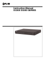
Instruction Manual
D3300 D3200 SERIES
Instruction Manual
D3300 D3200 SERIES
#LX400005; r. 6.0/23115/23116; en-US
iii
Thank you for purchasing this product. FLIR is committed to providing our customers with a high quality,
reliable security solution.
This manual refers to the following models:
D3200 Series
D3300 Series
For the latest online manual, downloads and product updates, and to learn about our complete line of
accessory products, please visit our website at:
www.flirsecurity.com/pro
WARNING
RISK OF ELECTRIC SHOCK
DO NOT OPEN
WARNING: TO REDUCE THE RICK OF ELECTRIC SHOCK DO NOT REMOVE
COVER. NO USER SERVICABLE PARTS INSIDE.
REFER SERVICING TO QUALIFIED SERVICE PERSONNEL.
The lightning flash with arrowhead symbol, within an equilateral
triangle, is intended to alert the user to the presence of uninsulated
"dangerous voltage" within the product’s enclosure that may be of
sufficient magnitude to constitute a risk of electric shock.
The exclamation point within an equilateral triangle is intended to
alert the user to the presence of important operating and
maintenance (servicing) instructions in the literature accompanying
the appliance.
WARNING: TO PREVENT FIRE OR SHOCK HAZARD, DO NOT EXPOSE THIS UNIT
TO RAIN OR MOISTURE.
CAUTION: TO PREVENT ELECTRIC SHOCK, MATCH WIDE BLADE OF THE PLUG
TO THE WIDE SLOT AND FULLY INSERT.
#LX400005; r. 6.0/23115/23116; en-US
iv
Table of contents
1
Important Safeguards ..........................................................................1
1.1
General Precautions.................................................................... 1
1.2
Installation................................................................................. 1
1.3
Service ..................................................................................... 3
1.4
Use.......................................................................................... 3
2
Features .............................................................................................4
3
Getting Started....................................................................................5
4
Front Panel .........................................................................................6
4.1
4/8/12/16-Channel ...................................................................... 6
4.2
D3332 (32-Channel) .................................................................... 7
5
Rear Panel ..........................................................................................9
5.1
D3304 (4-Channel) ..................................................................... 9
5.2
D3308 (8-Channel) ..................................................................... 9
5.3
D3312 (12–Channel) ................................................................... 9
5.4
D3316 (16-Channel) .................................................................. 10
5.5
D3216 (16-Channel) .................................................................. 10
5.6
D3332 (32-Channel) .................................................................. 11
6
Basic Setup ...................................................................................... 12
6.1
Step 1: Connect the BNC Cameras............................................... 12
6.2
Step 2: Connect the Mouse......................................................... 12
6.3
Step 3: Connect the Ethernet Cable .............................................. 12
6.4
Step 4: Connect the Monitor........................................................ 12
6.5
Step 5: Connect the Power Adapter and Power on the DVR................ 13
6.6
Default System Password & Port Numbers ..................................... 13
6.7
Quick Access to System Information ............................................. 13
7
Mouse Control .................................................................................. 14
8
Remote Control ................................................................................. 15
8.1
Setting the Remote Control ID ..................................................... 16
9
Using the On-Screen Display .............................................................. 18
9.1
Using the Menu Bar................................................................... 18
9.2
Using the Virtual Keyboard and Mini-Keyboard ................................ 19
9.3
Using the Zoom Mode................................................................ 20
9.4
Using Picture in Picture (PIP) Mode .............................................. 21
10
Setting the Date and Time................................................................... 23
10.1
Configuring Daylight Savings Time (DST)....................................... 23
10.2
Using a NTP Server to set your System Time .................................. 24
11
Recording......................................................................................... 26
11.1
Event Recording ....................................................................... 26
11.2
Recording Audio....................................................................... 26
12
Playback and Backup......................................................................... 27
12.1
Playing Back Recorded Video ..................................................... 27
12.1.1 Using Playback Controls .................................................. 28
12.1.2 Finding Events in the Playback Bar .................................... 30
12.1.3 Controlling the Time Range of the Playback Bar.................... 30
12.1.4 Using Zoom in Playback Mode .......................................... 31
12.1.5 Using Video Clip Backup ................................................. 32
12.2
Backing Up Video ..................................................................... 33
12.3
Viewing Backed Up Video........................................................... 34
12.4
Converting Backed Up Video to AVI Files ....................................... 34
#LX400005; r. 6.0/23115/23116; en-US
v
Table of contents
13
Managing Passwords......................................................................... 36
13.1
Enabling and Changing Passwords............................................... 36
13.2
Adding Users ........................................................................... 37
14
Using the Main Menu ......................................................................... 39
14.1
Display ................................................................................... 39
14.1.1 Configuring Custom Channel Names.................................. 39
14.1.2 Changing the Position of the Channel Name......................... 40
14.1.3 Adjusting Camera Color Settings ....................................... 40
14.1.4 Enabling Covert Recording............................................... 41
14.1.5 Configuring the Time and Recording Time Display................. 41
14.1.6 Configuring Sequence Time ............................................. 41
14.1.7 Changing the Video-out Resolution .................................... 41
14.1.8 Restoring the System’s Resolution if you see a Blank
Screen......................................................................... 42
14.1.9 Adjusting Menu Transparency ........................................... 42
14.1.10 Adjusting the Video Margin............................................... 42
14.1.11 Adding Privacy Zones ..................................................... 43
14.1.12 Creating a Custom Split-screen Display .............................. 44
14.2
Record ................................................................................... 45
14.2.1 Configuring Pre-recording Settings..................................... 45
14.2.2 Configuring Backup File Duration (Pack Duration) ................. 46
14.2.3 Configuring the Recording Schedule (Continuous, Motion,
Alarm) ......................................................................... 46
14.2.4 Enabling Audio Recording................................................ 47
14.2.5 Configuring Recording Quality, Resolution, and Video
Frame Rate................................................................... 48
14.3
Search ................................................................................... 48
14.3.1 Searching for Video on the System .................................... 49
14.3.2 Backing up Video Files .................................................... 50
14.3.3 Using the Event Search ................................................... 51
14.3.4 Using the Log Search...................................................... 53
14.4
Network .................................................................................. 53
14.4.1 Configuring Network Type: DHCP & Static IP........................ 53
14.4.2 Enabling Auto Port Forwarding .......................................... 54
14.4.3 Changing the DVR’s Client and HTTP Port........................... 54
14.4.4 Adjusting Remote Connectivity Streaming Rates................... 55
14.4.5 Setting up Email Notification ............................................. 56
14.4.6 Setting Up an Email Notification Schedule ........................... 57
14.4.7 Configuring DDNS settings............................................... 58
14.5
Alarm ..................................................................................... 58
14.5.1 Configuring Motion Detection............................................ 58
14.5.2 Configuring Alarm Settings ............................................... 60
14.6
Device.................................................................................... 61
14.6.1 Configuring Hard Drive settings ......................................... 61
14.6.2 Formatting USB Flash Drive ............................................. 62
14.6.3 Formatting eSATA Backup Drives ...................................... 62
14.7
System ................................................................................... 63
14.7.1 Changing Date Format .................................................... 63
14.7.2 Changing Time Format .................................................... 63
14.7.3 Changing the System Language ........................................ 64
14.7.4 Changing Video Output - NTSC & PAL ................................ 64
#LX400005; r. 6.0/23115/23116; en-US
vi
Table of contents
14.8
14.7.5 Configuring Menu Time Out and Auto Logout ....................... 64
14.7.6 Adding Users & Changing the Admin Password .................... 64
14.7.7 Viewing System Information.............................................. 64
Advanced................................................................................ 64
14.8.1 Upgrading the System Firmware........................................ 64
14.8.2 Restoring to Factory Default Settings .................................. 65
14.8.3 Restarting or Shutting Down the DVR ................................. 66
14.8.4 Configuring System Warnings ........................................... 67
14.8.5 Saving Your System Configuration to a USB Flash
Drive ........................................................................... 68
14.8.6 Loading a System Configuration from a USB Flash
Drive ........................................................................... 68
15
Setting up Your DVR for Remote Connectivity ....................................... 70
15.1
System Requirements................................................................ 70
15.2
Accessing your DVR within a local network (LAN) ............................ 71
15.2.1 Step 1 of 3: Connect your DVR to the Local Area
Network ....................................................................... 71
15.2.2 Step 2 of 3: Obtain the DVR’s Local IP Address..................... 72
15.2.3 Step 3 of 3: Connect to the DVR’s Local IP Address ............... 72
15.3
Accessing your DVR Remotely over the Internet .............................. 74
15.3.1 Step 1 of 4: Port Forwarding ............................................. 74
15.3.2 Step 2 of 4: Create a DDNS Account .................................. 74
15.3.3 Step 3 of 4: Enable DDNS on the DVR ................................ 75
15.3.4 Step 4 of 4: Connect to the DDNS Address .......................... 76
16
Remote Viewing Interface ................................................................... 78
16.1
Changing Viewing Modes ........................................................... 79
16.2
Taking Screen Shots.................................................................. 79
16.3
Recording Video....................................................................... 79
16.4
Showing / Hiding Channels ........................................................ 79
16.5
Adjusting Sub-menu Options ....................................................... 80
16.6
Changing the Save Directory of Screenshots or Recorded
Video ..................................................................................... 80
16.7
Changing the Format of Recorded Video (PC Only) .......................... 80
16.8
Configuring PTZ Settings............................................................ 81
16.9
Video Playback ........................................................................ 82
16.9.1 Video Playback Controls .................................................. 83
16.10 Configuring Display Settings ....................................................... 84
16.11 Configuring Privacy Zone Settings ................................................ 84
16.12 Configuring Recording Parameters ............................................... 86
16.13 Configuring the Recording Schedule ............................................. 86
16.14 Configuring System Recording Quality .......................................... 87
16.15 Configuring Basic Network Settings .............................................. 88
16.16 Configuring the System Substream ............................................... 88
16.17 Configuring Email Notification Settings .......................................... 89
16.18 Configuring DDNS Settings......................................................... 90
16.19 Configuring Motion Detection Settings........................................... 90
16.20 Configuring your System to "Beep" During Motion ............................ 91
16.21 Configuring Alarm Notifications .................................................... 92
16.22 Configuring Hard Drive Recording Mode ........................................ 93
16.23 Configuring PTZ Parameters ....................................................... 93
16.24 Configuring the System Time and Date.......................................... 94
#LX400005; r. 6.0/23115/23116; en-US
vii
Table of contents
16.25
16.26
16.27
16.28
16.29
16.30
Changing the System’s Menu Time Out ......................................... 95
Configuring System User Accounts............................................... 95
Viewing System Information ........................................................ 96
Upgrading System Firmware ....................................................... 96
Restoring Default Settings .......................................................... 97
Configuring Event Settings.......................................................... 98
17
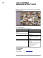
CMS-D3 CENTRAL MANAGEMENT SOFTWARE..................................... 99
17.1
System Requirements................................................................ 99
17.2
Installing CMS-D3 ..................................................................... 99
17.3
Adding DVRs ......................................................................... 100
17.3.1 Adding a DVR from the local area network (LAN) ................ 100
17.3.2 Adding a DVR using a DDNS address............................... 104
17.4
Control Panel ......................................................................... 106
17.5
Main View ............................................................................. 107
17.5.1 Using Multiple Windows or Monitors ................................. 109
17.5.2 Using Sequence Mode .................................................. 110
17.5.3 Using PTZ Controls ...................................................... 111
17.5.4 PTZ Controls............................................................... 111
17.5.5 Using PTZ Presets ....................................................... 112
17.5.6 Using PTZ Cruise ......................................................... 112
17.6
Remote Playback.................................................................... 112
17.6.1 Remote Playback Controls ............................................. 114
17.6.2 Downloading Video Files ............................................... 115
17.7
Group Device Management ...................................................... 117
17.7.1 Modifying DVRs ........................................................... 118
17.7.2 Deleting DVRs ............................................................. 119
17.7.3 Remotely Configuring DVRs ........................................... 119
17.7.4 Creating Camera Groups ............................................... 119
17.7.5 Modifying Camera Groups ............................................. 119
17.7.6 Deleting Camera Groups ............................................... 120
17.8
Local Log Search.................................................................... 120
17.8.1 Backing up Logs .......................................................... 121
17.9
Account Management.............................................................. 121
17.9.1 Enabling Passwords for the Admin Account ....................... 122
17.9.2 Adding User Accounts................................................... 122
17.9.3 Modifying User Accounts ............................................... 123
17.9.4 Deleting User Accounts ................................................. 123
17.10 Using File Management ........................................................... 124
17.11 Video Player .......................................................................... 125
17.11.1 Video Player Controls.................................................... 126
17.12 System Configuration .............................................................. 126
17.12.1 General...................................................................... 126
17.12.2 File ........................................................................... 127
17.12.3 Alarm Sound ............................................................... 127
18
FLIR Player: Playing Backed up Video on PC....................................... 129
18.1
Installing FLIR Player ............................................................... 129
18.2
Running FLIR Player................................................................ 129
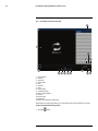
18.3
FLIR Player Interface Overview .................................................. 130
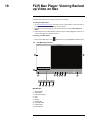
19
FLIR Mac Player: Viewing Backed up Video on Mac ............................. 132
19.1
FLIR Mac Player Interface......................................................... 132
#LX400005; r. 6.0/23115/23116; en-US
viii
Table of contents
19.2
19.3
Loading Individual Video Files ................................................... 133
Loading Multiple Video Files...................................................... 133
20
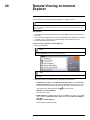
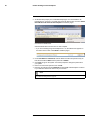
Remote Viewing on Internet Explorer ................................................. 134
21
Mobile Apps: Accessing your DVR Using a Mobile Device .................... 136
21.1
Compatible Devices and Platforms ............................................. 136
21.2
Before you Begin .................................................................... 136
21.3
iPhone.................................................................................. 136
21.3.1 System requirements .................................................... 136
21.3.2 Prerequisites ............................................................... 136
21.3.3 Connecting to your System Using Digi Summit.................... 137
21.3.4 Digi Summit Interface .................................................... 139
21.3.5 Using Remote Playback Mode on iPhone .......................... 141
21.3.6 Viewing Screenshots .................................................... 143
21.3.7 Viewing Manual Recordings ........................................... 143
21.3.8 Using Device Manager to Manage DVR’s .......................... 144
21.4
iPad ..................................................................................... 145
21.4.1 System requirements .................................................... 145
21.4.2 Prerequisites ............................................................... 145
21.4.3 Connecting to your System Using Digi SummitHD ............... 145
21.4.4 Digi Summit Interface .................................................... 146
21.4.5 Using Remote Playback Mode on iPad.............................. 148
21.4.6 Viewing Screenshots .................................................... 150
21.4.7 Viewing Manual Recordings ........................................... 150
21.4.8 Using Device Manager to Manage DVR’s .......................... 151
21.4.9 Managing Favorites ...................................................... 152
21.5
Android ................................................................................ 152
21.5.1 System requirements .................................................... 152
21.5.2 Prerequisites ............................................................... 152
21.5.3 Connecting to your System Using Digi Summit.................... 153
21.5.4 Digi Summit Interface .................................................... 155
21.5.5 Using Remote Playback Mode on Android ......................... 157
21.5.6 Viewing Screenshots .................................................... 159
21.5.7 Viewing Manual Recordings ........................................... 160
21.5.8 Using Device Manager to Manage DVR’s .......................... 161
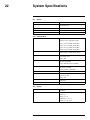
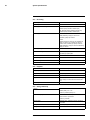
22
System Specifications ..................................................................... 163
22.1
System ................................................................................. 163
22.2
Inputs/Outputs ....................................................................... 163
22.3
Display ................................................................................. 163
22.4
Recording ............................................................................. 164
22.5
Playback............................................................................... 164
22.6
Storage & Backup ................................................................... 164
22.7
Network ................................................................................ 165
22.8
General ................................................................................ 165
23
Connecting a PTZ Camera ................................................................ 166
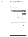
23.1
Configuring PTZ Settings.......................................................... 166
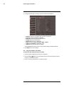
23.2
Using the PTZ Menu (Local DVR) ............................................... 167
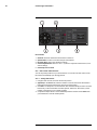
23.3
PTZ Presets and PTZ Cruise ..................................................... 168
23.3.1 Setting PTZ Presets...................................................... 168
23.3.2 Selecting PTZ Presets................................................... 169
23.3.3 Deleting PTZ Presets .................................................... 169
#LX400005; r. 6.0/23115/23116; en-US
ix
Table of contents
23.3.4 Starting / Stopping PTZ Cruise ........................................ 169
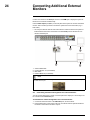
24
Connecting Additional External Monitors ........................................... 170
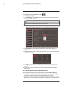
24.1
Customizing the Channel Arrangement on the External
Monitor ................................................................................. 170
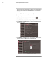
24.2
Main and Spot Video Outputs (D3316/D3332 Only) ........................ 171
24.2.1 Configuring the Spot Monitor for Full-Screen or SplitScreen....................................................................... 172
25
Recording Audio ............................................................................. 174
26
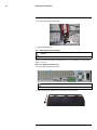
Replacing the Hard Drive.................................................................. 175
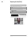
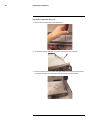
26.1
Removing the Hard Drive.......................................................... 175
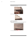
26.2
Installing the Hard Drive ........................................................... 176
26.3
Installing Hard Drives (D3332) ................................................... 178
26.4
Formatting the Hard Drive......................................................... 181
27
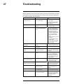
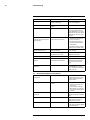
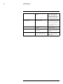
Troubleshooting .............................................................................. 182
27.1
Troubleshooting Remote Connections ......................................... 183
28
Notices........................................................................................... 185
28.1
FCC/IC Notice........................................................................ 185
28.2
Modification........................................................................... 185
28.3
RoHS ................................................................................... 185
#LX400005; r. 6.0/23115/23116; en-US
x
1
Important Safeguards
In addition to the careful attention devoted to quality standards in the manufacturing process of your product, safety is a major factor in the design of every instrument. However,
safety is your responsibility too. This sheet lists important information that will help to ensure your enjoyment and proper use of the product and accessory equipment. Please read
them carefully before operating and using your product.
1.1 General Precautions
1. All warnings and instructions in this manual should be followed.
2. Remove the plug from the outlet before cleaning. Do not use liquid aerosol detergents.
Use a water-dampened cloth for cleaning.
3. Do not use this product in humid or wet places.
4. Keep enough space around the product for ventilation. Slots and openings in the storage cabinet should not be blocked.
5. It is highly recommended to connect the product to a surge protector to protect from
damage caused by electrical surges. It is also recommended to connect the product to
an uninterruptible power supply (UPS), which has an internal battery that will keep the
product running in the event of a power outage.
CAUTION
Maintain electrical safety. Power line operated equipment or accessories connected to this product
should bear the UL listing mark or CSA certification mark on the accessory itself and should not be modified so as to defeat the safety features. This will help avoid any potential hazard from electrical shock or
fire. If in doubt, contact qualified service personnel.
1.2 Installation
1. Read and Follow Instructions - All the safety and operating instructions should be
read before the product is operated. Follow all operating instructions.
2. Retain Instructions - The safety and operating instructions should be retained for future reference.
3. Heed Warnings - Comply with all warnings on the product and in the operating
instructions.
4. Polarization - Do not defeat the safety purpose of the polarized or grounding-type
plug.
A polarized plug has two blades with one wider than the other.
A grounding type plug has two blades and a third grounding prong.
The wide blade or the third prong are provided for your safety.
If the provided plug does not fit into your outlet, consult an electrician for replacement
of the obsolete outlet.
#LX400005; r. 6.0/23115/23116; en-US
1
1
Important Safeguards
5. Power Sources - This product should be operated only from the type of power source
indicated on the marking label. If you are not sure of the type of power supplied to your
location, consult your video dealer or local power company. For products intended to
operate from battery power, or other sources, refer to the operating instructions.
6. Overloading - Do not overload wall outlets or extension cords as this can result in the
risk of fire or electric shock. Overloaded AC outlets, extension cords, frayed power
cords, damaged or cracked wire insulation, and broken plugs are dangerous. They
may result in a shock or fire hazard. Periodically examine the cord, and if its appearance indicates damage or deteriorated insulation, have it replaced by your service
technician.
7. Power-Cord Protection - Power supply cords should be routed so that they are not
likely to be walked on or pinched by items placed upon or against them. Pay particular
attention to cords at plugs, convenience receptacles, and the point where they exit
from the product.
8. Surge Protectors - It is highly recommended that the product be connected to a
surge protector. Doing so will protect the product from damage caused by power
surges. Surge protectors should bear the UL listing mark or CSA certification mark.
9. Uninterruptible Power Supplies (UPS) - Because this product is designed for continuous, 24/7 operation, it is recommended that you connect the product to an uninterruptible power supply. An uninterruptible power supply has an internal battery that will
keep the product running in the event of a power outage. Uninterruptible power supplies should bear the UL listing mark or CSA certification mark.
10. Ventilation - Slots and openings in the case are provided for ventilation to ensure reliable operation of the product and to protect it from overheating. These openings must
not be blocked or covered. The openings should never be blocked by placing the product on a bed, sofa, rug, or other similar surface. This product should never be placed
near or over a radiator or heat register. This product should not be placed in a built-in
installation such as a bookcase or rack unless proper ventilation is provided and the
product manufacturer’s instructions have been followed.
11. Attachments - Do not use attachments unless recommended by the product manufacturer as they may cause a hazard.
12. Water and Moisture - Do not use this product near water — for example, near a bath
tub, wash bowl, kitchen sink or laundry tub, in a wet basement, near a swimming pool
and the like.
13. Heat - The product should be situated away from heat sources such as radiators, heat
registers, stoves, or other products (including amplifiers) that produce heat.
14. Accessories - Do not place this product on an unstable cart, stand, tripod, or table.
The product may fall, causing serious damage to the product. Use this product only
with a cart, stand, tripod, bracket, or table recommended by the manufacturer or sold
with the product. Any mounting of the product should follow the manufacturer’s instructions and use a mounting accessory recommended by the manufacturer.
15. Camera Extension Cables – Check the rating of your extension cable(s) to verify
compliance with your local authority regulations prior to installation.
16. Mounting - The cameras provided with this system should be mounted only as instructed in this guide or the instructions that came with your cameras, using the provided mounting brackets.
#LX400005; r. 6.0/23115/23116; en-US
2
1
Important Safeguards
17. Camera Installation - Cameras are not intended for submersion in water. Not all cameras can be installed outdoors. Check your camera environmental rating to confirm if
they can be installed outdoors. When installing cameras outdoors, installation in a
sheltered area is required.
1.3 Service
1. Servicing - Do not attempt to service this product yourself, as opening or removing
covers may expose you to dangerous voltage or other hazards. Refer all servicing to
qualified service personnel.
2. Conditions Requiring Service - Unplug this product from the wall outlet and refer
servicing to qualified service personnel under the following conditions:
•
•
•
•
•
When the power supply cord or plug is damaged.
If liquid has been spilled or objects have fallen into the product.
If the product has been exposed to rain or water.
If the product has been dropped or the cabinet has been damaged
If the product does not operate normally by following the operating instructions. Adjust only those controls that are covered by the operating instructions. Improper adjustment of other controls may result in damage and will often require extensive
work by a qualified technician to restore the product to its normal operation.
• When the product exhibits a distinct change in performance. This indicates a need
for service.
3. Replacement Parts - When replacement parts are required, have the service technician verify that the replacements used have the same safety characteristics as the original parts. Use of replacements specified by the product manufacturer can prevent fire,
electric shock, or other hazards.
4. Safety Check - Upon completion of any service or repairs to this product, ask the
service technician to perform safety checks recommended by the manufacturer to determine that the product is in safe operating condition.
1.4 Use
1. Cleaning - Unplug the product from the wall outlet before cleaning. Do not use liquid
cleaners or aerosol cleaners. Use a damp cloth for cleaning.
2. Product and Cart Combination - When product is installed on a cart, product and
cart combination should be moved with care. Quick stops, excessive force, and uneven surfaces may cause the product and cart combination to overturn.
3. Object and Liquid Entry - Never push objects of any kind into this product through
openings as they may touch dangerous voltage points or “short-out” parts that could
result in a fire or electric shock. Never spill liquid of any kind on the product.
4. Lightning - For added protection of this product during a lightning storm, or when it is
left unattended and unused for long periods of time, unplug it from the wall outlet and
disconnect the antenna or cable system. This will prevent damage to the product due
to lightning and power line surges.
#LX400005; r. 6.0/23115/23116; en-US
3
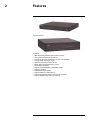
2
Features
4/8/12/16-channel
32-channel
•
•
•
•
•
•
•
•
•
•
•
•
•
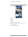
960H Super-Res (960x480) with real-time recording
34% greater resolution than standard D1
True aspect ratio wide screen format, sharper, non-stretched
Looping, HDMI, VGA, Spot outputs
CMS-D3 remote access SW, multi-site
Mobile Apps: iPhone®, Android™, iPad®
Fully PC/Mac compatible
Supports additional HDDs for expandible storage
Pentaplex operation
FLIR DDNS service included
Supports USB 2.0 or eSata back-up
Auto Port Forwarding wizard for easy remote connection
Supports RS485 (PTZ), Audio I/O, Alarm I/O
#LX400005; r. 6.0/23115/23116; en-US
4
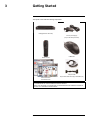
3
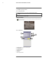
Getting Started
The system comes with the following components:
DVR (Digital Video Recorder)
12V DC power Supply*
(may not be exactly as shown)
USB Mouse
Remote Control
Octopus Cable
Quick Start Guides
Only included with: D3316 (x2), D3332/3216 (x1)
Documentation CD
HARD DRIVE SIZE, NUMBER OF CHANNELS, AND CAMERA CONFIGURATION MAY VARY BY MODEL. PLEASE REFER TO YOUR PACKAGE FOR SPECIFIC DETAILS.
CHECK YOUR PACKAGE TO CONFIRM THAT YOU HAVE RECEIVED THE COMPLETE SYSTEM, INCLUDING ALL COMPONENTS SHOWN ABOVE.
#LX400005; r. 6.0/23115/23116; en-US
5
4
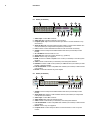
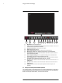
Front Panel
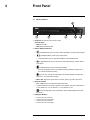
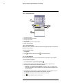
4.1 4/8/12/16-Channel
1. IR Sensor: IR receiver for the remote control.
LED Indicators:
• PWR: Power LED.
• HDD: Hard disk activity LED.
2. Menu & Playback Controls:
•
•
: In Playback Mode, press to rewind. Press repeatedly to increase rewind speed.
: In Playback Mode, press to play / pause video.
• In Viewing mode, press to open Search Menu to select playback time.
•
•
: In Playback Mode, press to fast forward. Press repeatedly to increase fast forward speed.
: In Playback Mode, press to stop video playback.
• In Live Viewing Mode, press to stop DVR recording. Password required; does
not override scheduled recording.
•
: Press to stop / resume recording. When the channel displays a red box with
the letter "C", the channel is recording.
• Menu / Esc: Opens the system menu. In menus, press to go back / exit menus.
3. Channel Controls:
• Ch1 ~ Ch0: Press to view channel in Full-screen View.
• (16-Channel models) To access channels 10 and greater: Press 0 for channel 10 or
1+0 for channel 10, 1+1 for channel 11, 1+2 for channel 12, etc.
•
: In Live Viewing Mode, press repeatedly to switch between Split-screen Viewing modes.
4. Navigation Buttons:
•
•
•
•
▲: Press to move cursor up.
▼: Press to move cursor down.
◀: Press to move cursor left.
▶: Press to move cursor right.
#LX400005; r. 6.0/23115/23116; en-US
6
4
Front Panel
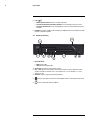
5. PTZ /
:
• Within system menus: Press to confirm a selection.
• To open the System Information window: In Live Viewing mode, press once.
• To open PTZ Controls: In Live Viewing Mode, press once and release then press
and hold.
6. USB Port: Connect a USB mouse (included) or USB flash drive (not included) for data
backup or firmware updates.
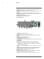
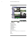
4.2 D3332 (32-Channel)
1. LED Indicators:
• PWR: Power LED.
• HDD: Hard disk activity LED.
2. IR Sensor: IR receiver for the remote control.
3. Ch1 ~ Ch0: Press to view channel in Full-screen View. To access channels 10 and
greater: Press 0 for channel 10 or 1+0 for channel 10, 1+1 for channel 11, 1+2 for
channel 12, etc.
4. CH-/CH+: Press to select previous/next channel.
5.
: Press to open split-screen view. Press multiple times to select split-screen mode.
6.
: Press to start/stop Sequence Mode.
#LX400005; r. 6.0/23115/23116; en-US
7
4
Front Panel
7. Menu & Playback Controls:
: In Playback Mode, press to rewind. Press repeatedly to increase rewind speed.
•
: In Playback Mode, press to play / pause video.
•
• In Viewing mode, press to open Search Menu to select playback time.
•
: In Playback Mode, press to fast forward. Press repeatedly to increase fast forward speed.
•
: In Playback Mode, press to stop video playback.
• In Live Viewing Mode, press to stop DVR recording. Password required; does
not override scheduled recording.
•
: Press to stop / resume recording. When the channel displays a red box with
the letter "C", the channel is recording.
• Menu / Esc: Opens the system menu. In menus, press to go back / exit menus.
8. Navigation Buttons:
•
•
•
•
▲: Press to move cursor up.
▼: Press to move cursor down.
◀: Press to move cursor left.
▶: Press to move cursor right.
9. PTZ /
:
• Within system menus: Press to confirm a selection.
• To open the System Information window: In Live Viewing mode, press once.
• To open PTZ Controls: In Live Viewing Mode, press once and release then press
and hold.
• USB Port: Connect a USB mouse (included) or USB flash drive (not included) for
data backup or firmware updates.
#LX400005; r. 6.0/23115/23116; en-US
8
5
Rear Panel
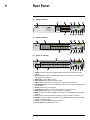
5.1 D3304 (4-Channel)
5.2 D3308 (8-Channel)
5.3 D3312 (12–Channel)
1. eSATA: Connect a self-powered eSATA external hard drive (not included) for data
backup.
2. Audio Input: BNC inputs for audio-enabled cameras (not included) or self-powered
microphones (not included).
3. Video Input: Connect BNC cameras.
4. Video Output: BNC output for external monitor.
5. VGA: Connect a VGA monitor (not included) to view the system interface.
6. PTZ / Alarm Block: Connect compatible PTZ cameras (not included) or alarm devices
(not included).
7. IR-EXT: Service only; not supported.
8. Loop Out: BNC outputs to connect each channel to a Loop Out monitor.
9. Audio Output: BNC output for 1 audio channel (e.g. speakers).
10. HDMI: Connect to a HDMI-compatible TV or monitor (not included) to view the system
interface.
11. LAN: Connect a CAT 5 RJ45 Ethernet cable for local and remote connectivity.
12. USB Port: Connect a USB mouse (included) or USB flash drive (not included) for data
backup or firmware updates.
13. DC12V: Connect the included AC power adapter.
14. On / Off Switch: Turns the DVR on or off.
#LX400005; r. 6.0/23115/23116; en-US
9
5
Rear Panel
5.4 D3316 (16-Channel)
1. Video Input: Connect BNC cameras.
2. Video Out: BNC outputs for external or spot monitors.
3. Loop Out (CH1~16): Connect included Octopus cable to connect channels to Loop
Out monitors.
4. Audio In (CH1~16): Connect included Octopus cable to connect audio-enabled cameras (not included) or self-powered microphones (not included).
5. LAN: Connect a CAT 5 RJ45 Ethernet cable for local and remote connectivity.
6. eSATA: Connect a self-powered eSATA external hard drive (not included) for data
backup.
7. On / Off Switch: Turns the DVR on or off.
8. Audio Out: BNC output for 2 audio channels (e.g. speakers).
9. IR-EXT: Service only; not supported.
10. HDMI: Connect to a HDMI-compatible TV or monitor (not included) to view the system
interface.
11. VGA: Connect a VGA monitor (not included) to view the system interface.
12. USB Port: Connect a USB mouse (included) or USB flash drive (not included) for data
backup or firmware updates.
13. PTZ / Alarm Block: Connect compatible PTZ cameras (not included) or alarm devices
(not included).
14. DC12V: Connect the included AC power adapter.
5.5 D3216 (16-Channel)
1. eSATA: Connect a self-powered eSATA external hard drive (not included) for data
backup.
2. Audio Input: BNC inputs for audio-enabled cameras (not included) or self-powered
microphones (not included).
3. Video Input: Connect BNC cameras.
4. Video Output: BNC output for external monitor.
5. VGA: Connect a VGA monitor (not included) to view the system interface.
6. PTZ / Alarm Block: Connect compatible PTZ cameras (not included) or alarm devices
(not included).
7. IR-EXT: Service only; not supported.
8. Loop Out 5~16: Connect Octopus cable to connect channels 5~16 to a Loop Out
monitor.
#LX400005; r. 6.0/23115/23116; en-US
10
5
Rear Panel
9. Loop Out 1~4: BNC outputs to connect channels 1~4 to a Loop Out monitor.
10. Audio Out: BNC output for 1 audio channel (e.g. speakers).
11. HDMI: Connect to a HDMI-compatible TV or monitor (not included) to view the system
interface.
12. LAN: Connect a CAT 5 RJ45 Ethernet cable for local and remote connectivity.
13. USB Port: Connect a USB mouse (included) or USB flash drive (not included) for data
backup or firmware updates.
14. DC12V: Connect the included AC power adapter.
15. On / Off Switch: Turns the DVR on or off.
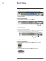
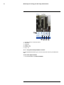
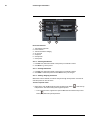
5.6 D3332 (32-Channel)
1. Video Input: Connect BNC cameras.
2. Video Output: BNC output for external or spot monitors.
3. eSATA: Connect a self-powered eSATA external hard drive (not included) for data
backup.
4. IR-EXT: Service only; not supported.
5. AC Input: Connect the included AC power cable.
6. On / Off Switch: Turns the DVR on or off.
7. PTZ / Alarm Block: Connect compatible PTZ cameras (not included) or alarm devices
(not included).
8. Not supported
9. VGA: Connect a VGA monitor (not included) to view the system interface.
10. LAN: Connect a CAT 5 RJ45 Ethernet cable for local and remote connectivity.
• USB Port: Connect a USB mouse (included) or USB flash drive (not included) for
data backup or firmware updates.
11. HDMI: Connect to a HDMI-compatible TV or monitor (not included) to view the system
interface.
12. Audio In 5~16: Connect Octopus cable to connect audio-enabled cameras (not included) or self-powered microphones (not included) to channels 5 through 16.
13. Audio Out: BNC output for 2 audio channels (e.g. speakers).
14. Line in: Service only; not supported.
15. Audio In: BNC inputs for audio-enabled cameras (not included) or self-powered microphones (not included) connected to channels 1 through 4.
16. Loop Out 1~16: BNC outputs to connect channels 1~16 to a Loop Out monitor.
#LX400005; r. 6.0/23115/23116; en-US
11
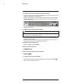
6
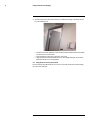
Basic Setup
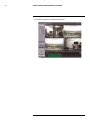
6.1 Step 1: Connect the BNC Cameras
• Connect BNC cameras to the Video Input ports on the rear panel of the DVR.
8–channel model shown
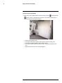
6.2 Step 2: Connect the Mouse
• Connect a USB mouse (included) to one of the USB ports.
8–channel model shown
6.3 Step 3: Connect the Ethernet Cable
• Connect an Ethernet cable (not included) to the LAN port on the rear panel of the DVR.
Connect the other end of the Ethernet cable to a router on your network.
8–channel model shown
6.4 Step 4: Connect the Monitor
• Connect an HDMI cable (not included) from the HDMI port to the TV or monitor
(recommended).
• Connect a VGA cable (not included) from the VGA port to the monitor.
#LX400005; r. 6.0/23115/23116; en-US
12
6
Basic Setup
6.5 Step 5: Connect the Power Adapter and Power on the DVR
• Connect the included power adapter to the DC 12V port. Connect the end of the power
adapter to a wall socket or a surge protector.
• Turn the power switch to I to turn on the DVR. At startup, the system performs a basic
system check and runs an initial loading sequence. After a few moments, the system
loads a live display view.
8–channel model shown
6.6 Default System Password & Port Numbers
CAUTION
By default, the system user name is admin and the password is 000000. Passwords are enabled by default and are required to access the Menu Bar or Main Menu. It is essential that you create your own password. For details, see 13 Managing Passwords, page 36
• The system requires a user name and password to log in to the system remotely using
a computer or mobile device.
• ALL the system port numbers below must be port forwarded on your router to log in to
your system over the Internet or an internal network (LAN).
Local DVR user name and password:
• Username: admin / Password: 000000
Default ports for remote access:
• Port 80 (HTTP port)
• Port 9000 (Client port)
Remote connectivity (LAN & Internet) to the DVR:
• User Name: admin
• Password: 000000
6.7 Quick Access to System Information
• To quickly open a window that displays vital system information, press the PTZ /
button on the front panel of the system.
#LX400005; r. 6.0/23115/23116; en-US
13
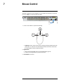
7
Mouse Control
The DVR is designed for mouse navigation. To use a USB mouse (included), connect the
mouse to a USB port on the rear panel of the DVR.
1. Use the mouse buttons to perform the following:
• Left-Button: Click to select a menu option. During live viewing in Split-screen View,
double-click on a channel to view the selected channel in full-screen; double-click
the channel again to return to Split-screen View.
2. Right-Button:
• Click to open the Menu Bar (see 9.1 Using the Menu Bar, page 18).
• In menus, use the right-button to go back / exit menus.
3. Scroll-Wheel: No function.
#LX400005; r. 6.0/23115/23116; en-US
14
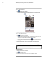
8
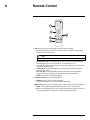
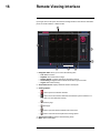
Remote Control
1. REC: Press to resume recording after recording has been stopped.
• ID: This button controls ID function for remote control. For details, see 8.1 Setting
the Remote Control ID, page 16.
NOTE
• Number Keys (1-0): In Live Viewing Mode, press to open the desired channel in
Full-screen view. Press 1+0 for channel 10, 1+1 for channel 11, etc.
• 0: Press 0 three times to show the mouse cursor on the BNC monitor or the monitor
connected with HDMI / VGA.
• Display Mode: In Live Viewing Mode, press repeatedly to switch through splitscreen viewing modes.
• 2x2 / 3x3 / 4x4: In Live Viewing Mode, press to open the corresponding Splitscreen View. Press repeatedly to change channels shown in split-screen.
• AUTO: Press to start / stop Sequence Mode.
2. Navigation Cursors: Press to navigate menus.
• ENTER: In menus, press to confirm selections.
• In Live Viewing Mode, press to access System Information.
3. MENU / ESC: Press to open the system menu. In menus, press to go back / exit menu.
• MUTE: In Live Viewing and Playback Modes, press to mute / un-mute audio.
• PIP: In Live Viewing Mode, press once to open Picture in Picture (PIP) 1X1 or twice
to open PIP 1X2. Mouse is required to change channels shown in PIP.
#LX400005; r. 6.0/23115/23116; en-US
15
8
Remote Control
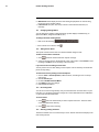
4. Playback Controls:
• FWD: In Playback Mode, press to fast forward / increase fast forward speed.
• REW: In Playback Mode, press to rewind / increase rewind speed.
• PLAY: In Playback Mode, press to play / pause video.
• In Live Viewing Mode, press to open the Record Search Menu.
• STOP: In Playback Mode, press to pause playback.
• In Live Viewing Mode, press to stop recording. Password required; does not
override scheduled recording.
• SLOW: In Playback Mode, press to play video in slow motion. Press repeatedly to
change slow motion playback speed.
• PAUSE / FRAME: In Playback Mode, press to pause. Press repeatedly to view recordings frame by frame.
5. PTZ Controls:
•
•
•
•
Z+ / Z-: Adjust camera Zoom.
F+ / F- : Adjust camera Focus.
I+ / I-: Adjust camera Iris.
PTZ: Opens the PTZ menu.
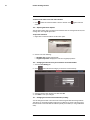
8.1 Setting the Remote Control ID
If you have more than one DVR, you can use the ID function to pair the remote control with
a specific DVR.
To pair the remote control:
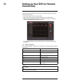
1. On the DVR, right-click to open the menu bar and click
.
2. Enter the DVR user name (default: admin) and password (default: 000000).
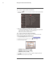
3. Click System > Control Device.
4. Under System ID, enter the desired ID number.
5. Click Apply to save your settings. Right-click repeatedly to return to live view.
#LX400005; r. 6.0/23115/23116; en-US
16
8
Remote Control
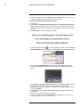
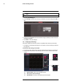
6. On the remote control press ID, then press the ID number you entered in step 4 and
press Enter to confirm.
NOTE
You do not need to enter 0’s in the ID for unused digits. For example, if the ID is "004," press ID > 4 >
Enter.
#LX400005; r. 6.0/23115/23116; en-US
17
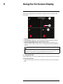
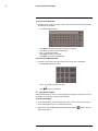
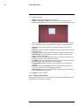
9
Using the On-Screen Display
Use the system’s graphical on-screen display to navigate menus and configure options
and settings.
1. Date & Time: Displays the date and time on the system
2. Record Status: Displays the current recording status of the system: C=continuous
(normal recording); M=motion recording; A=alarm recording.
3. Channel number / Channel title: Displays channel number or channel title. To rename the channel number to a title, see 14.1.1 Configuring Custom Channel Names,
page 39.
NOTE
If you can’t see your mouse cursor on screen:
You may have switched output modes from VGA / HDMI to BNC. By default, the DVR outputs to VGA
/ HDMI mode. To change the video output, press 0 three times on the remote control.
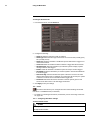
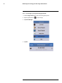
9.1 Using the Menu Bar
The Menu Bar allows you to access the Main Menu and control basic functions of the DVR.
To access the Menu Bar:
1. Right-click or move the mouse cursor to the bottom of the screen to access the Menu
Bar.
#LX400005; r. 6.0/23115/23116; en-US
18
9
Using the On-Screen Display
1.1.
1.2.
Main Menu: Opens the Main Menu.
Lock: Click to lock the Main Menu unless the password is entered. Lock icon is
not visible unless passwords are enabled.
1.3. Split Screen buttons: Select split-screen layout.
1.4. PTZ: Opens the PTZ controls.
1.5. Start / Stop PTZ Cruise: Start or stop the PTZ cruise function.
1.6. Zoom: Opens digital zoom. Must be in Full-screen / Live Viewing Mode.
1.7. Record Search: Opens the DVR Search Menu. This allows you to search for
video recorded on the DVR.
1.8. Start / Stop Recording: Start or stop DVR recording on all channels. Password required; does not override scheduled recording.
1.9. Start / Stop SEQ: Start or stop Sequence Mode. In Sequence Mode, DVR automatically switches between channels every few seconds.
1.10. PIP 1X1: Enable Picture in Picture Mode with 1 camera in full screen and 1 in a
small window.
1.11. PIP 1X2: Enable Picture in Picture Mode with 1 camera in full screen and 2 in
small windows.
1.12. Volume: Adjust the DVR volume (audio-capable cameras required, not
included).
9.2 Using the Virtual Keyboard and Mini-Keyboard
You can input numeric or text values using the on-screen virtual keyboard. You will need to
use the Virtual Keyboard when entering your User ID and Password. The Virtual Mini-Keyboard is used to input numeric values, such as the time and date.
#LX400005; r. 6.0/23115/23116; en-US
19
9
Using the On-Screen Display
To use the Virtual Keyboard:
1. Using the mouse, click on an option or field, such as the User ID and Password fields
(if passwords are enabled).
• The Virtual Keyboard opens.
•
•
•
•
•
Click Shift to switch between upper and lowercase letters.
Click ◀ ▶ to move the cursor between letters.
Click ← to backspace/delete.
Click Enter to enter your selection.
Click ESC to close the virtual keyboard.
To use the Virtual Mini-Keyboard:
1. Using the mouse, click on an option or field, such as the Time or Date fields.
• The Virtual Mini-Keyboard opens.
• Click ← to go back to the previous option.
• Click
to enter your selection.
9.3 Using the Zoom Mode
Zoom Mode allows you to zoom in on an image while viewing your cameras live. This can
be useful if you want to get a closer look at a situation.
To use the Zoom Mode:
1. In Live Viewing Mode, select the channel you want to zoom in on in full-screen (double-click the channel if you are in a Split-screen View).
2. Right-click to open the Menu Bar and select the Zoom button (
pears on the screen.
#LX400005; r. 6.0/23115/23116; en-US
). A Zoom icon ap-
20
9
Using the On-Screen Display
3. Click and drag on the area of the screen you would like to enlarge. The image zooms
in on the selected area.
• The box in the lower right-hand corner shows the entire camera picture with a black
box around the zoomed-in area.
• Click inside the box and drag to move the zoom area.
• Right-click to exit and select a different zoom area. Right-click again to exit Zoom
Mode and return to Live Viewing Mode.
9.4 Using Picture in Picture (PIP) Mode
Picture in Picture (PIP) Mode allows you to view one channel in full-screen while viewing
up to two other channels.
#LX400005; r. 6.0/23115/23116; en-US
21
9
Using the On-Screen Display
To use Picture in Picture Mode:
1. Right-click to open the Menu Bar and select the PIP1X1 button (
) or PIP1X2 button
(
). PIP1X1 shows 1 channel in full screen and 1 other channel; PIP1X2 shows 1
channel in full screen and 2 other channels.
•
•
•
•
Picture in Picture Mode opens.
To change the full-screen channel, click anywhere in the main viewing area.
To change the smaller channels, click inside the channel.
To move the smaller channels around the screen, click inside the white bar and
drag.
• Right-click to exit and return to Live Viewing Mode.
#LX400005; r. 6.0/23115/23116; en-US
22
10
Setting the Date and Time
CAUTION
It is highly recommended to set the date and time when first setting up your system.
Inaccurate time stamps may render your footage unusable for court evidence.
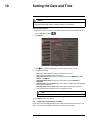
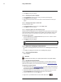
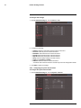
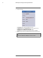
To set the date and time:
1. Right-click or move your mouse to the bottom of the screen to open the Menu Bar and
click the Main Menu button (
).
2. Click System.
Press
on the Mini-Keyboard after you have entered the Date or Time
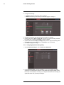
3. Configure the following:
• Date: Click inside the field and enter the month, date, and year.
• Time: Click inside the field and enter the time.
• (Optional) Date Format: Use the drop-down menu to select MM/DD/YY or, DD/
MM/YY, or YY-MM-DD.
• (Optional) Time Format: Use the drop-down menu to select 12HOURS or
24HOURS.
• (Optional) DST: Click the Setup button next to DST to configure automatic Daylight
Savings Time adjustments.
• (Optional) NTP: Click the Setup button next to NTP to synchronize your DVR’s
time and date with a Network Time Protocol (NTP) time server.
NOTE
A constant internet connection is required for the NTP server feature to function.
4. Click Apply to save your settings.
10.1 Configuring Daylight Savings Time (DST)
If your region observes Daylight Savings Time (DST), follow the instructions below to configure your DVR to automatically update the time when the clock updates.
#LX400005; r. 6.0/23115/23116; en-US
23
10
Setting the Date and Time
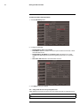
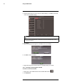
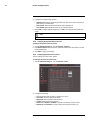
To enable automatic DST adjustments:
1. Click the DST Setup button.
2. Configure the following:
• Daylight Saving Time: Select Enable.
• Time Offset: Select the number of hours the system should move forward or backward when DST occurs.
• Daylight Saving Time Mode: Select Week or Date. This allows you to select
whether DST should begin and end at the beginning of the week or on a specific
date.
• Start Time, End Time: Enter when DST starts and ends.
3. Click Apply to save your settings.
10.2 Using a NTP Server to set your System Time
A NTP (Network Time Protocol) server syncs your system time with an online time server.
NOTE
A constant Internet connection is required to use the NTP feature.
#LX400005; r. 6.0/23115/23116; en-US
24
10
Setting the Date and Time
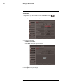
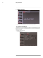
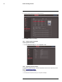
To enable NTP:
1. Right-click to open the Menu Bar and click the Main Menu button (
).
2. Click System. Beside NTP, click Setup.
3. Configure the following:
• Enable: Select Enable.
• Server Address: Select the NTP server address.
• Time Zone: Select your region’s time zone.
4. Click Update Now to connect to the time server.
5. Click Apply to save your settings.
#LX400005; r. 6.0/23115/23116; en-US
25
11
Recording
By default, the system is set to immediately record video from connected cameras in Continuous Recording Mode.
•
Recording—Continuous: Normal, continuous recording
You can set the system to stop recording once the hard drive is full, or to continually record
by overwriting previously recorded data. For more details, see 14.6.1 Configuring Hard
Drive settings, page 61.
11.1 Event Recording
The system also includes motion and alarm recording:
•
•
Recording—Motion: The system records when motion is detected by the camera
Recording—Alarm: The system records when an external senor device (not included) is triggered
11.2 Recording Audio
The system can also record audio. You must have audio-capable cameras (not included)
or self-powered microphones (not included) in order to record audio on the system.
For details, see 25 Recording Audio, page 174.
#LX400005; r. 6.0/23115/23116; en-US
26
12
Playback and Backup
You can view and back up recorded video on the system through the Search Menu.
12.1 Playing Back Recorded Video
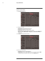
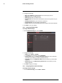
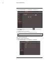
To playback a specific date and time:
1. Right-click to open the Menu Bar and click the Record Search button (
cord Search tab opens.
). The Re-
2. Configure the following:
• CH: Select the channel you wish to search. Select All to search all channels.
• Search Date: Enter the month, date, and year you wish to search for video.
• Playback Time: Enter the desired time you wish to search for video.
3. Click Play to select the exact time specified in Playback Time.
4. Select the channel or channels you want to play back and click Play.
#LX400005; r. 6.0/23115/23116; en-US
27
12
Playback and Backup
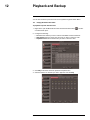
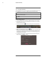
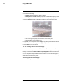
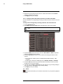
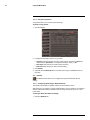
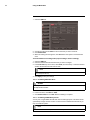
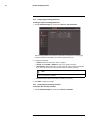
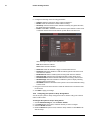
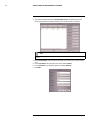
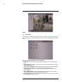
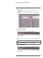
To search for recorded footage on the DVR:
1. Right-click to open the Menu Bar and click the Record Search button (
cord Search tab opens.
). The Re-
2. Configure the following:
• CH: Select the channel you wish to search. Select All to search all channels.
• Search Date: Enter the month, date, and year you wish to search for video.
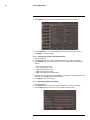
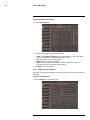
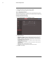
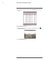
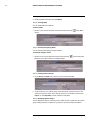
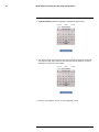
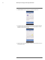
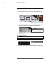
3. Click the Search button. Your search results appear in the calendar. In the top portion
of the calendar, results are shown for each day in the month. In the bottom portion, results are shown for each hour in the selected day.
Search results:
Green: Continuous recording
Red: Motion or alarm recording
Grey: No recording
4.
5.
6.
7.
Click on a date in the calendar to see the video available for that date.
Click on the hour of the video you want to play back.
Select the channel or channels you want to play back.
Click Play to begin playback.
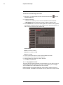
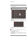
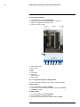
12.1.1
Using Playback Controls
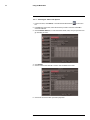
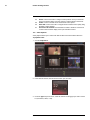
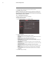
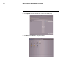
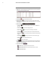
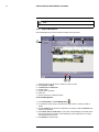
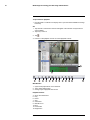
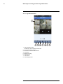
This system features advanced playback controls that allow you to see when you have recorded footage and motion events on your cameras. They also allow you to use digital
zoom in playback mode or take backups from short video clips.
Different playback controls appear depending on the number of cameras you have selected to playback. All available controls appear when you playback from a single camera.
#LX400005; r. 6.0/23115/23116; en-US
28
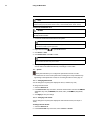
12
Playback and Backup
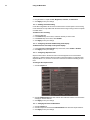
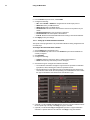
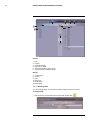
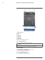
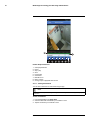
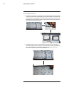
1. Progress bar: Shows available footage for the selected time period as different colors.
D3304 / D3308 / D3216:
•
: Continuous recording
•
: Alarm or motion recording
D3312 / D3316 / D3332:
•
: Continuous recording
•
: Motion recording
•
: Alarm recording
•
: A+M (Alarm+Motion) recording
2. Start time of footage shown in bar
3. Rewind
4. Slow
5. Play
6. Pause
7. Fast Forward
8. Zoom
9. Video clip backup
10. Mute
11. Exit playback
12. End time of footage shown in bar
13. Show playback time controls
14. Change range of time shown in playback bar
To use the advanced playback controls:
1. Move the mouse slightly to display the on-screen playback controls. You can also use
the playback control buttons on the remote control.
• Click the playback controls to play, pause, fast forward, rewind, and slow down
playback.
• Click X or right-click to quit playback and return to the Search Menu.
#LX400005; r. 6.0/23115/23116; en-US
29
12
Playback and Backup
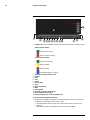
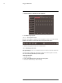
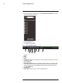
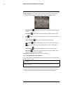
12.1.2
Finding Events in the Playback Bar
The advanced playback controls show the time and type of video footage available. The
playback bars are color coded to show different recording types:
• D3304 / D3308 / D3216: Continuous recordings are shown in green and motion or
alarm recordings are in red.
• D3312 / D3316 / D3332: Continuous recordings are shown in green, motion recordings
in yellow, alarm recordings in red, and A+M (alarm + motion) recordings in blue.
• All models: White spaces indicate that no recordings are available.
NOTE
Motion detection and/or alarms must be enabled for each channel before they will be highlighted, for
details see 14.5 Alarm, page 58.
When up to four channels are selected for playback, multiple channels are shown.
D3304 / D3308 / D3216
D3312 / D3316 / D3332
If more than four channels are selected, one bar is shown that combines all the selected
channels. This means that video available on any selected channel will be shown in the
bar.
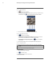
12.1.3
Controlling the Time Range of the Playback Bar
The time range is the start and end times of the footage displayed in the Playback bar. By
default, the Playback bar displays recordings recorded on the day selected for playback
(from 00:00~24:00). You can change the time range to narrow in on a specific time.
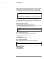
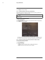
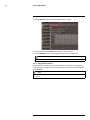
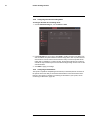
To control the time range of the Playback bar:
1. During Playback mode, click
#LX400005; r. 6.0/23115/23116; en-US
to open the time range controls.
30
12
Playback and Backup
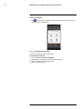
2. Click 30m, 1H, 2H, or 24H to select a time range. For example, if 30m is selected, the
playback bar will show 15 minutes before to 15 minutes after the currently playing time.
OR
• To create a custom time range, click
. The button will become colored. Move
your mouse to the time you where you would like the range to start and click. Then,
move your mouse to the time you where you would like the range to end and click.
The start and end times will be replaced by the 1st and 2nd times that you clicked
on.
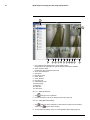
12.1.4
Using Zoom in Playback Mode
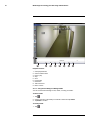
You can use Zoom in Playback Mode. This is useful if you need a closer look at recorded
video.
NOTE
Zoom is only available when a single channel is selected for Playback.
To use zoom in playback mode:
1. Open Playback mode with only one channel selected. For details, see 12.1 Playing
Back Recorded Video, page 27.
2. Click
to open Zoom.
NOTE
Playback controls are not available when Zoom is activated. If you want to pause the video before
you zoom, you will have to pause it before entering Zoom.
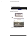
3. Click and drag on the area of the screen you would like to enlarge. The image zooms
in on the selected area.
• The box in the lower right-hand corner shows the entire camera picture with a black
box around the zoomed-in area.
• Click inside the box and drag to move the zoom area.
4. Right-click to exit and select a different zoom area. Right-click again to exit Zoom
Mode and return to Playback Mode.
#LX400005; r. 6.0/23115/23116; en-US
31
12
Playback and Backup
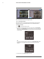
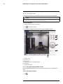
12.1.5
Using Video Clip Backup
Video clip backup allows you to select a duration of video during playback mode and save
it to a USB flash drive (not included) or eSATA external hard drive (not included).
NOTE
You must format an eSATA hard drive before you can use it to backup data. For information on formatting
backup drives, see 14.6 Device, page 61.
NOTE
Video clip backup is only available when a single channel is selected for Playback.
To create a backup video clip:
1. Connect a USB flash drive (not included) or eSATA external hard drive to the DVR.
2. Open Playback mode with only one channel selected. For details, see 12.1 Playing
Back Recorded Video, page 27.
3. Click the clip backup button (
) to start your backup at the current playback time.
4. When you want the backup clip to stop, click
again.
TIP: You can use fast forward or click-and-drag the video cursor to select the stop time
for the clip. This is useful because it allows you to backup longer segments of video
without having to watch the whole video each time. You must have enough space on
your backup drive to save the file.
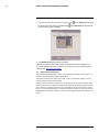
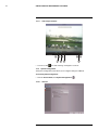
5. A confirmation window appears, showing information about the backup file you are
about to create. Click Backup to confirm.
#LX400005; r. 6.0/23115/23116; en-US
32
12
Playback and Backup
6. Check AVI or H264 to select the backup video file type and click Apply. Wait for the file
to be saved before removing the USB memory drive.
For details on viewing backed up video, see 18 FLIR Player: Playing Backed up Video
on PC, page 129 or 19 FLIR Mac Player: Viewing Backed up Video on Mac, page 132.
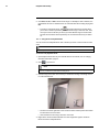
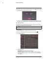
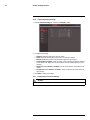
12.2 Backing Up Video
You can back up video to a USB flash drive (not included) or eSATA external hard drive
(not included) connected to the rear panel of the DVR.
NOTE
For information on formatting USB or eSATA drives, see 14.6 Device, page 61.
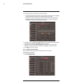
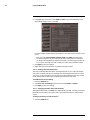
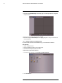
To back up video:
1. Connect a USB flash drive or eSATA external hard drive to the DVR.
2. Right-click to open the Menu Bar and click the Record Search button (
).
3. Click the Event Search tab.
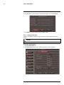
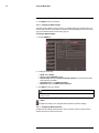
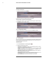
4. Configure the following:
•
•
•
•
Search Date: Enter the desired month, date, and year
Search Time: Enter the time range you wish to search.
CH: Select the channel you wish to search. To search all channels, select All.
Type: Select the type of recording you wish to search. Choose from All, Continuous, or Alarm.
#LX400005; r. 6.0/23115/23116; en-US
33
12
Playback and Backup
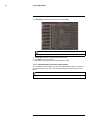
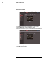
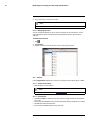
5.
6.
7.
8.
9.
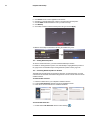
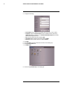
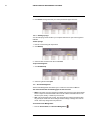
Click Search. A list of videos populate in the window.
Click ◀ ▶ to scroll through the list of videos. The videos are named by time.
Click the BAK checkbox beside the video you wish to back up.
Click Backup.
Check AVI or H264 to select the backup video file type and click Apply.
10. Wait for the backup to finish before removing the USB memory drive.
12.3 Viewing Backed Up Video
To view the downloaded video, you must install the FLIR Player software.
For details on viewing backed up video, see 18 FLIR Player: Playing Backed up Video on
PC, page 129 or 19 FLIR Mac Player: Viewing Backed up Video on Mac, page 132.
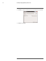
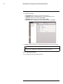
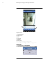
12.4 Converting Backed Up Video to AVI Files
The DVR saves its backup files as proprietary video files. To share these files, you must
convert them into .AVI files. Note that the AVI generator can also convert audio from audioenabled cameras.
To install the AVI converter:
1. Insert the software disc in your computer’s CD/DVD rom drive.
2. Locate the AVI Generator software from the CD installation wizard.
3. Follow the on-screen instructions to install AVI Generator.
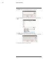
To start the AVI Generator:
1. Double-click the AVI Generator shortcut on the desktop (
#LX400005; r. 6.0/23115/23116; en-US
).
34
12
Playback and Backup
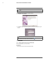
2. Click Open and then locate the backed up video file on your hard drive.
3. Select the desired file format (.264 , h.264, All File) that you wish to search for. Click
Open.
4. Click Start to convert and save the file in the default save folder.
• Or click Save As to select a desired save folder, then click Start to convert the file.
5. Locate the file in the folder you selected in step 4.
#LX400005; r. 6.0/23115/23116; en-US
35
13
Managing Passwords
WARNING
By default, the system user name is admin and the password is 000000. Passwords are required to access the Menu Bar or Main Menu or to log into the system remotely.
• ADMIN—system administrator: has full control of the system, and can change both administrator and user passwords and enable/disable password protection.
• USER—normal user: only has access to live viewing, search, playback, and other functions. You may set up multiple USER accounts with varying levels of access to the
system.
For security reasons, it is essential to create a custom password for the system.
13.1 Enabling and Changing Passwords
You can change the system password of user accounts from the Users menu.
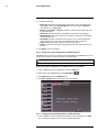
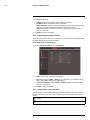
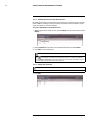
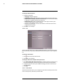
To enable the admin password:
1. Right-click to open the Menu Bar and click the Main Menu button (
).
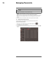
2. Click System and select the Users tab.
3. Select the checkbox beside admin to change the admin password, then click the Edit
button.
#LX400005; r. 6.0/23115/23116; en-US
36
13
Managing Passwords
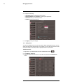
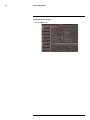
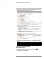
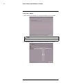
4. Configure the following:
•
•
•
•
User Name: Enter the desired admin user name.
Password Enable: Select Enable to enable system passwords.
Password: Enter your desired password.
Confirm: Re-enter the password.
5. Click Apply to save your settings.
13.2 Adding Users
You can allow multiple users to log in to the system. When adding different users, you can
assign what menus they have access to. For example, you may want your friend to monitor
your system while you are away, while not giving full access to your system.
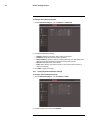
To add a new user:
1. Right-click to open the Menu Bar and click the Main Menu button (
).
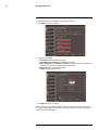
2. Click System > Users tab.
3. Select the checkbox beside User1 (or any other user), then click the Permission
button.
#LX400005; r. 6.0/23115/23116; en-US
37
13
Managing Passwords
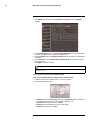
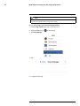
4. Select the menus and channels the user will have access to.
5. Click Apply to save your settings.
6. Configure the following:
• User Name: Enter the desired user name.
• User Enable: Select Enable to enable the user account.
• Password Enable: Select Enable or Disable to enable or disable the system from
prompting you for a user or admin password during log in.
• Password: Enter your desired password.
• Confirm: Re-enter the password.
7. Click Apply to save your settings.
Now, you can log in to the system locally, or remotely using the user name or password
you created. When logging into the system with a user account, the user will only have access to the menus you assigned.
#LX400005; r. 6.0/23115/23116; en-US
38
14
Using the Main Menu
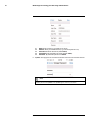
To open the Main Menu:
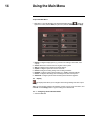
• Right-click to open the Menu Bar and click the Main Menu button (
). Enter the
system user name (default: admin) and password (default: 000000) and click Apply.
1. Display: Configure display options (e.g. camera color settings, camera title, video
output).
2. Search: Search for recorded video and log files on the system.
3. Alarm: Configure motion detection and alarm settings.
4. System: Configure system time and user accounts.
5. Record: Configure recording settings and recording schedules.
6. Network: Configure system network settings (e.g. DDNS, email alert settings).
7. Device: Configure PTZ settings, HDD recording mode, HDD format option.
8. Advanced: Configure system restart schedule, perform firmware upgrades.
14.1 Display
The display menu allows you to configure camera image settings and video output
settings.
Tip: If you want to apply settings to all channels, use the "Copy To" drop-down menu, and
select All. Click the Copy button to copy the setting across all channels.
14.1.1
Configuring Custom Channel Names
1. Select the Live tab.
#LX400005; r. 6.0/23115/23116; en-US
39
14
Using the Main Menu
2. In the Channel drop-down menu, select the channel that you wish to rename.
3. Click the Name field. Use the Virtual Keyboard to enter in the new channel name.
4. Click Apply to save your settings.
14.1.2
Changing the Position of the Channel Name
1. Select the Live tab.
2. In the Channel drop-down menu, select the channel you would like to configure.
3. In the Position drop-down menu, select where you would like the channel names to
appear:
•
•
•
•
•
U-L: Upper left hand corner.
D-L: Lower left hand corner.
U-R: Upper right hand corner.
D-R: Lower right hand corner.
OFF: Do not display the channel name.
4. (Optional) Use the drop-downs next to Copy to copy settings to another channel or all
channels. Click the Copy button to copy settings.
5. Click Apply to save your settings.
14.1.3
Adjusting Camera Color Settings
1. Select the Live tab.
2. In the Channel drop-down menu, select the channel that you wish to configure.
3. Click the Setup button next to Color. The Color Setup window opens.
#LX400005; r. 6.0/23115/23116; en-US
40
14
Using the Main Menu
4. Drag the sliders to adjust the Hue, Brightness, Contrast, and Saturation.
5. Click Apply to save your settings.
14.1.4
Enabling Covert Recording
Covert Recording blanks out the screen so that it seems as if the system is not recording.
Covert channels are only visible when the admin account logs in using a remote computer
or mobile device.
To enable covert recording:
1.
2.
3.
4.
Select the Live tab.
In the Channel drop-down menu, select the channel you wish to hide.
In the Covert drop-down menu, select Enable.
Click Apply to save your settings.
14.1.5
Configuring the Time and Recording Time Display
To add/remove the time stamp in the system display:
1. In the Live Time and Record Time drop-down menu, select enable or disable.
2. Click Apply to save your settings.
14.1.6
Configuring Sequence Time
Sequence time refers to the amount of time a channel appears on the screen before
changing to a different channel when the DVR is in Sequence Mode. For example, when
Sequence Mode is on, channel 1 is shown for several seconds before switching to channel 2.
To configure the sequence time:
1. Click the Output tab.
2. Click the SEQ Dwell time field and enter the time channels remains on-screen before
changing to another channel.
3. Click Apply to save your settings.
14.1.7
Changing the Video-out Resolution
1. Click the Output tab.
2. Click the drop-down menu beside VGA Resolution and select the output resolution.
3. Click Apply to save your settings.
#LX400005; r. 6.0/23115/23116; en-US
41
14
Using the Main Menu
4. Right-click repeatedly to exit all menus. The DVR prompts you to restart. Click OK.
5. The DVR restarts and asks you to confirm the new resolution. Click Yes to confirm or
No to revert to the old resolution. If you do nothing, the DVR will revert to the last selected resolution and restart.
NOTE
If you select a resolution that is greater than what your monitor supports, you may see a blank screen
when your DVR restarts. If this occurs, do not do anything and wait until the DVR restarts. If the
screen remains blank, press and hold the Stop button on the remote control until the DVR restarts.
Your system resolution will default to 1024 x 768.
14.1.8
Restoring the System’s Resolution if you see a Blank Screen
If you see a blank screen on your monitor after turning on your system, the DVR’s output
resolution may be higher than what your monitor supports. Follow the steps below to restore the DVR’s default resolution to 1024 x 768.
To restore the DVR’s default resolution:
1. Ensure the power and video cables are properly connected.
2. Press and hold the Stop button on the remote control until the DVR restarts. The DVR
will restart with the default resolution of 1024 x 768.
3. When the DVR restarts, click Yes to confirm the default resolution.
NOTE
If your system resolution is already in 1024 x 768, pressing and holding the Stop button will not restart
the system.
14.1.9
Adjusting Menu Transparency
You can increase or decrease the transparency of the on-screen menus.
To adjust the transparency of on-screen menus:
1. Click the Output tab.
2. Drag the Transparency slider to adjust transparency.
3. Click Apply to save your settings.
14.1.10
Adjusting the Video Margin
If you connect your DVR to a BNC monitor, you can adjust the video margins.
NOTE
You must select the BNC output mode to adjust the margins. Press 0 three times on the remote control to
switch the output mode between BNC mode and VGA/HDMI mode. When BNC mode is selected, the
mouse cursor appears on the BNC monitor.
To adjust the video margin:
1. Click the Output tab.
2. Click the Margin button.
#LX400005; r. 6.0/23115/23116; en-US
42
14
Using the Main Menu
3. Drag the sliders to the left or right to adjust the Left, Right, Top, or Bottom Margin.
4. Click Apply to save your settings and click OK to confirm.
14.1.11
Adding Privacy Zones
A privacy zone allows you to block out up to 4 portions of each channel with a black
square.
WARNING
Areas covered by privacy zones are not visible in recordings.
To configure a privacy zone:
1. Click the Privacy Zone tab.
2. In the Channel drop-down menu, select the channel you wish to configure.
#LX400005; r. 6.0/23115/23116; en-US
43
14
Using the Main Menu
3. Configure the following:
• Channel: Select the channel you wish to configure.
• Privacy Zone: Select ON to enable privacy zones or OFF to disable privacy zones.
• Area Setup: Select the Area1~4 checkboxes to enable up to 4 privacy zones.
4. Click the Setup button next to Mask Area. The Privacy Area setup screen opens.
• Click on a privacy area and drag to change its location.
• Click on the edge of a privacy area and drag to resize a privacy area.
• Right-click when you are finished to exit.
5. (Optional) Use the drop-downs next to Copy to copy privacy areas to another channel
or all channels. Click the Copy button to copy privacy areas.
6. Click Apply to save your settings.
14.1.12
Creating a Custom Split-screen Display
You can create a custom split-screen display and re-arrange where channels are placed.
TIP: You can use the steps below to create a custom split-screen display on a secondary
monitor connected to the Video Out (Main on D3316/D3332) port. First, move the mouse
and system interface to the Video Out monitor by pressing 0 three times on the remote
control. Complete the steps, and then press 0 three times on the remote control again to
return the mouse and system interface to the VGA or HDMI monitor. Your custom display
will be saved on the secondary monitor.
To re-arrange the split-screen display:
1. Select the Output tab.
#LX400005; r. 6.0/23115/23116; en-US
44
14
Using the Main Menu
2. Under View Setup, select Enable. This lets you select and arrange the channels you
want to show on the screen.
NOTE
Enabling View Setup disables your ability to change channels the normal way on the selected monitor. You will need to disable View Setup to return to normal operation.
3. Under View Mode, select the desired viewing mode: Single, Quad, Nine, or Sixteen.
4. Click Vout Setup. A menu appears that allows you to select the arrangement of
channels.
5. Click the drop-down menus to select which channels to show on the screen and the arrangement of channels.
6. Click Apply to save changes. Click Ok. Right-click repeatedly to exit all menus and return to live viewing.
14.2 Record
The Record menu allows you to configure recording settings, such as the recording
resolution, recording schedule, and audio recording.
14.2.1
Configuring Pre-recording Settings
1. Select the Rec Para tab.
2. In the Channel drop-down menu, select the desired channel you wish to configure.
3. In the PreRecord drop-down menu, select Enable to enable pre-recording or Disable
to disable pre-recording.
#LX400005; r. 6.0/23115/23116; en-US
45
14
Using the Main Menu
4. Click Apply to save your settings.
14.2.2
Configuring Backup File Duration (Pack Duration)
"Pack Duration" refers to the duration of a backed up file in the system. By default, a recording is "packaged" into 15 minute video files.
NOTE
This feature is not supported on D3312 / D3316 / D3332, which package video files into files of a maximum size of 255MB.
To change the DVR’s backed up file size:
1. Select the Rec Para tab.
2. In the Pack Duration drop-down menu, select the desired duration (15~60 minutes).
3. Click Apply to save your settings.
Changing the file size changes the duration of backed up files. For example, if you select 15 minutes as your file size, the system stores video files in 15 minute durations.
14.2.3
Configuring the Recording Schedule (Continuous, Motion, Alarm)
To configure the recording schedule:
1. Click the Schedule tab.
2. Configure the following:
• Channel: Select the channel you wish to configure the schedule for.
• Week: Select the day of the week you wish to configure.
#LX400005; r. 6.0/23115/23116; en-US
46
14
Using the Main Menu
3. Click inside the grid to configure the recording schedule:
• The recording schedule is arranged as a grid. Each row represents a recording type
(Continuous, Motion, and Alarm), and each box represents an hour.
• Recording for each recording type is enabled during the selected hour when the
box is filled in with the corresponding color. Recording for each recording type is
disabled for the selected hour when the box is gray.
4. (Optional): Use the top Copy and Copy To drop-down to copy the recording schedule
to a specific day or all days. Click Copy to copy the schedule.
5. (Optional): Use the bottom Copy and Copy To drop-down to copy the recording
schedule to a specific channel or all channels. Click Copy to copy the schedule.
6. Click Apply to save your settings.
14.2.4
Enabling Audio Recording
Audio-capable cameras are required (not included) for audio recording.
To enable audio recording:
1. Click the MainStream tab.
#LX400005; r. 6.0/23115/23116; en-US
47
14
Using the Main Menu
2. Beside the corresponding channel, select or deselect the checkbox under Audio to
enable or disable audio recording.
3. Click Apply to save your settings.
14.2.5
Configuring Recording Quality, Resolution, and Video Frame Rate
You can configure the recording quality, recording resolution and video frame rate for each
channel.
To change the recording quality, recording resolution, and video frame rate:
1. Click the MainStream tab.
2. Under Mode, select D1 or 960H. 960H will enable larger, wide-screen formats.
NOTE
If you change this setting, the DVR will restart when you save changes.
3. Under the Quality drop-down menu, select from Good, Better, or Best to adjust the
quality of recordings on each channel.
4. Under the Resolution drop-down menu, select the Recording Resolution for each
channel:
• If D1 is selected, available options are CIF (320x240), HD1 (720x240), or D1
(720x480).
• If 960H mode is selected, available options are 480x240, 960x240, or 960x480.
5. Under the FPS drop-down menu, select the number of frames per second you want
the DVR to record on each channel.
6. (Optional) Use the Copy and Copy To drop-down menus to copy recording settings to
one or all channels. Click Copy to copy recording settings.
7. Click Apply to save your settings.
14.3 Search
The Search menu allows you to search for saved video on your system for playback
and backup.
#LX400005; r. 6.0/23115/23116; en-US
48
14
Using the Main Menu
14.3.1
Searching for Video on the System
1. In the main menu, click Search, or click the Search Menu button (
bar.
) in the menu
2. In the CH drop-down menu, select the channel you wish to search or select All to
search all channels.
3. Click the Search Date field, to enter the desired month, date, and year you wish to begin searching for video.
4. Click Search.
5. Click on a date in the calendar to see the video available for that date.
6. Click on the hour of the video you want to play back.
#LX400005; r. 6.0/23115/23116; en-US
49
14
Using the Main Menu
7. Select the channel or channels you want to play back.
8. Click Play to begin playback.
14.3.1.1
Video Playback Controls
Move the mouse slightly to display the on-screen playback controls. You can also use the
playback control buttons on the remote control or front panel of the system.
• Click X to quit playback and return to the Search menu.
14.3.2
Backing up Video Files
You can back up video files on your USB flash drive (not included) or external eSATA hard
drive (not included).
You must format an eSATA hard drive before you may use it with the system. For details,
see 14.6.3 Formatting eSATA Backup Drives, page 62.
To back up video files:
1. Perform a search.
2. Insert a blank USB flash drive in the rear panel of the system.
3. Click on the desired date you wish to back up.
#LX400005; r. 6.0/23115/23116; en-US
50
14
Using the Main Menu
4. Click the Backup button. A list of files appears in the Log menu.
5. Click the checkbox under BAK next to the file you want to backup.
6. Click the Backup button to begin copying the video files to your flash drive.
NOTE
You will need the FLIR Player (included on the CD) to view the saved files.
14.3.3
Using the Event Search
Event Search allows you to find videos that are marked as a specific recording type (e.g.,
motion recording). This allows you to quickly and easily sort through videos that only have
certain attributes.
NOTE
Videos are not marked as Alarm unless continuous recording is turned off and motion or alarm settings
are enabled.
#LX400005; r. 6.0/23115/23116; en-US
51
14
Using the Main Menu
To perform an Event Search:
1. Click the Event Search tab.
2. Configure the following:
•
•
•
•
Search Date: Enter the Month, Date, and Year.
CH: Select the channels you wish to search.
Search Time: Enter the time range you wish to search.
Type: Select the recording type you wish to search for. Choose from Normal (continuous recording), Motion, Alarm, or A+M (alarm + motion; D3312 / D3316 /
D3332 only).
3. Click Search. A list populates with videos.
4. Perform one of the following:
• Play video: Double-click on the desired file.
• Back up a file: Connect a blank USB flash drive to your system. Select the BAK
checkbox beside the desired file name. Then, click the Backup button.
#LX400005; r. 6.0/23115/23116; en-US
52
14
Using the Main Menu
14.3.4
Using the Log Search
A log search allows you to search system event logs.
To perform a Log search:
1. Click the Log tab.
2. Configure the following to perform a Log search:
• Log Type: Select the log type you wish to search under. Choose from Alarm (i.e.
motion events), Operation (i.e. Configuration changes, Setup), or All.
• Start Time: Enter the time you wish to begin searching.
• End Time: Enter the time you wish to end searching.
3. Click Search.
4. (Optional) Click the Backup button to backup system logs to a USB flash drive (not
included).
14.4 Network
The Network menu allows you to configure the system’s DDNS and network
settings.
14.4.1
Configuring Network Type: DHCP & Static IP
The system has the ability to operate in DHCP mode and Static IP mode.
After setting up your system, it is highly recommended to set your system to use a static IP
address. This ensures that the IP address will not change if the power goes out or your
router resets.
To configure DHCP and Static IP settings:
1. Select the Network tab.
#LX400005; r. 6.0/23115/23116; en-US
53
14
Using the Main Menu
2. In the Type drop-down menu, select DHCP or Static. If you select DHCP, the router
automatically assigns an IP to your DVR.
If you select Static, click the field beside IP Address, and enter in the IP address of your
choice.
• Enter your custom Subnet Mask, Gateway, DNS1 and DNS2 using the mouse.
• You must assign the IP in your router that you wish to make static. For example, if
you assign 192.168.2.89 as the static IP in the DVR, you must assign 192.168.2.89
in your router as a static IP as well. Consult your router’s user’s manual for details.
3. Click Apply to save your settings.
4. Right-click until you exit all menus. You will be prompted to restart.
14.4.2
Enabling Auto Port Forwarding
Auto Port Forwarding allows the DVR to open required ports on your router. This feature
only works on certain router models. If the Auto Port Forwarding feature does not work on
your router, it is recommended to use the Auto Port Forwarding Wizard (PC only), located
on the software CD. You may have to manually open the port on your router.
To Enable Auto Port Forwarding:
1. Select the Network tab.
2. In the Auto Port Forwarding drop-down menu, select Enable or Disable.
3. Click Apply to save your settings.
14.4.3
Changing the DVR’s Client and HTTP Port
The DVR’s Default Client port is 9000. The default HTTP port is 80. You must port forward
the Client Port and HTTP port on your router to your DVR’s IP address to enable remote
access.
To change the Client port and HTTP port:
1. Select the Network tab.
#LX400005; r. 6.0/23115/23116; en-US
54
14
Using the Main Menu
2. In Client Port, enter the desired Client Port (default: 9000).
NOTE
9000 is represented as "09000."
3. In HTTP Port, enter the desired HTTP Port (default: 80).
4. Click Apply to save your settings.
5. Right-click to exit all menus. You will be prompted to restart.
14.4.4
Adjusting Remote Connectivity Streaming Rates
You can adjust the data streaming rate (also called the SubStream) when you connect to
the system remotely. If you want to conserve bandwidth, select a lower frame rate and
bitrate.
NOTE
Setting your system to stream with a lower frame and bitrate may cause the video to appear choppy or
slow.
#LX400005; r. 6.0/23115/23116; en-US
55
14
Using the Main Menu
To adjust the SubStream settings:
1. Click the SubStream tab.
2. Configure the following beside the desired channel:
• Video: Select Enabled or Disabled. If you select Disabled, you will not be able to
view the channel when connecting remotely to the system.
• FPS: Select the desired frames per second.
• Bitrate: Select the desired video bitrate.
• Audio: Select or deselect the checkbox to enable or disable the system from
streaming audio when viewing the system remotely.
3. Click Apply to save your settings.
14.4.5
Setting up Email Notification
The system can send email notifications when it detects motion or when an alarm parameter triggers.
To set up email notification:
1. Click the Email tab in the Network menu.
#LX400005; r. 6.0/23115/23116; en-US
56
14
Using the Main Menu
2. From the Email drop-down menu, select Enable.
3. Configure the following:
•
•
•
•
SSL: Select Enable or Disable to configure Secure Socket Layer protocol.
SMTP Port: Enter your SMTP address.
SMTP Server: Enter your SMTP Server.
Sender Email: Enter the sender email address. This can be any address of your
choice.
• Sender Password: Enter your email server’s password.
• Receiver Email: Enter the recipient’s email address.
• Interval: Enter the interval the DVR waits before sending a new email notification.
4. Click Apply to save your settings.
14.4.6
Setting Up an Email Notification Schedule
The system can be programmed to only send email notifications during designated hours
on certain days.
To configure the email notification schedule:
1. Click the Email tab in the Network menu.
2. Ensure the Email drop-down menu is set to Enable and your email credentials are
correctly configured.
3. Click Schedule.
4. Configure the following:
• Channel: Select the channel you wish to configure the schedule for.
• Week: Select the day of the week you wish to configure.
5. Click inside the grid to configure the notification schedule:
• The notification schedule is arranged as a grid. Each row represents a notification
type (Motion, Alarm, Warning) and each box represents an hour.
• Email notifications for each notification type are enabled during the selected hour
when the box is filled in with the corresponding color. Notifications for each notification type are disabled for the selected hour when the box is gray.
6. (Optional): Use the top Copy and Copy To drop-downs to copy the notification schedule to a specific day or all days. Click Copy to copy the schedule.
7. (Optional): Use the bottom Copy and Copy To drop-downs to copy the notification
schedule to a specific channel or all channels. Click Copy to copy the schedule.
#LX400005; r. 6.0/23115/23116; en-US
57
14
Using the Main Menu
8. Click Apply to save your settings.
14.4.7
Configuring DDNS settings
You must create a DDNS account and enter your DDNS settings into the DVR before you
can remotely connect to your system. For details on creating a DDNS account, see 15 Setting up Your DVR for Remote Connectivity, page 70.
To configure DDNS settings:
1. Click the DDNS tab.
2. Configure the following:
• DDNS: Select Enable.
• Server: Select FLIRDDNS (default).
• Domain Name: Enter the Domain name/URL Request you received in the email
after registering for DDNS.
• User Name: Enter your DDNS User Name.
• Password: Enter your DDNS Device password.
3. Click Apply to save your settings.
NOTE
Please allow 10~15 minutes for the DDNS servers to update with your new DDNS address before attempting to connect.
14.5 Alarm
The Alarm tab allows you to configure Motion Detection and Alarm settings.
14.5.1
Configuring Motion Detection
Configure motion settings to determine the area you wish to monitor for motion events,
and the outcome if a motion event occurs.
#LX400005; r. 6.0/23115/23116; en-US
58
14
Using the Main Menu
To configure motion settings:
1. Select the Motion tab.
#LX400005; r. 6.0/23115/23116; en-US
59
14
Using the Main Menu
2. Configure the following:
• Channel: Select the channel you wish to configure.
• Enable: Select Enable or Disable to activate or deactivate motion recording.
• Area: Click the Setup button to configure the area of the screen that detects motion.
Click and drag the mouse cursor to configure motion detection areas. Motion detection is enabled in red areas and disabled in transparent areas. Right-click to exit.
• Sensitivity: Select motion sensitivity. The greater the number, the greater the
sensitivity.
• Alarm Out: Select the checkbox to enable the system to trigger a device connected
to the alarm block.
• Latch Time: Enter the duration the alarm continues to trigger after the event ends.
• Show Message: Select the checkbox if you want the system to display a system
message when an alarm triggers.
• Buzzer: Select the duration the system will "beep" when motion is detected. Or select OFF to disable the "beep" during motion events.
• Send Email: Select the checkbox if you want the system to send email notifications
if an alarm triggers. Email notifications must be configured.
• Record Channel: Select the channel you wish the DVR to record during motion
recording.
• Full Screen: Select the Full Screen check box so that the system goes into full
screen mode when motion or an alarm trigger is detected.
• Post Recording: Enter the post recording duration (the time the system continues
to record after a motion event occurs).
3. Click Apply to save your settings.
14.5.2
Configuring Alarm Settings
The Alarm settings menu allows you to configure how the system behaves when an external alarm device (not included) is triggered.
#LX400005; r. 6.0/23115/23116; en-US
60
14
Using the Main Menu
To configure the Alarm tab:
1. From the Alarm menu, click the Alarm tab.
2. Configure the following:
• Alarm In: Select the channel you wish to configure.
• Alarm Type: Select the alarm type of the device. Choose from N/O (normally open),
N/C (normally closed).
• Alarm Out: Select the checkbox to enable the system’s alarm block to trigger a connected external alarm.
• Latch Time: Enter the duration the alarm continues to trigger after the event ends.
• Show Message: Select the checkbox if you want the system to display a system
message when an alarm triggers.
• Buzzer: Select the checkbox to enable the system to "beep" if an alarm triggers.
• Send Email: Select the checkbox if you want the system to send email notifications
if an alarm triggers.
• Post Recording: Select the duration the system continues to record as an event
after the alarm trigger ends. For example, if you select 30s (30 seconds), the system
continues to record for 30 seconds after the alarm trigger ends.
• Full Screen: Select the Full Screen check box so that the system goes into full
screen mode when motion or an alarm trigger is detected.
3. Click Apply to save your settings.
14.6 Device
The Device menu allows you to configure hard drive and PTZ settings and format
hard drives or a USB flash drive (not included).
• For details on connecting PTZ cameras (not included), see 23 Connecting a PTZ Camera, page 166.
14.6.1
Configuring Hard Drive settings
To format the hard drive:
WARNING
Formatting the HDD erases all data on the hard disk.
This step cannot be undone.
#LX400005; r. 6.0/23115/23116; en-US
61
14
Using the Main Menu
1. Select the HDD tab.
2. Click the checkbox under Select to choose the drive you wish to reformat.
3. Click Format HDD.
4. When the warning window appears, click OK. Wait for the system to format the hard
drive.
To set the hard drive recording mode (loop recording or linear recording):
1. Select the HDD tab.
2. Select the checkbox beside the hard drive you wish to configure.
3. In the Overwrite drop-down menu, select Auto (recommended), or select the desired
duration the hard drive should retain its data.
NOTE
If overwrite recording is enabled, the system’s hard drive automatically re-writes the hard drive’s oldest content (first in first out).
4. Click Apply to save your settings.
14.6.2
Formatting USB Flash Drive
WARNING
Formatting a USB flash drive erases all data on the drive.
This step cannot be undone.
1. Insert a USB flash drive (not included) into one of the USB ports.
2. In the main menu, click Device > HDD.
3. Click Format USB, then click OK. Wait for formatting to complete.
14.6.3
Formatting eSATA Backup Drives
You may use a single eSATA external hard drive for backup purposes. This allows for the
quick backup of large amounts of data. You must format an eSATA hard drive before you
may use it with the system.
NOTE
The eSATA hard drive must be self-powered to work with the system.
#LX400005; r. 6.0/23115/23116; en-US
62
14
Using the Main Menu
NOTE
You may use any size eSATA hard drive with the system. However, the system will only use the first
350GB for backup purposes (D3304 / D3308 / D3216) or the first 900GB (D3312 / D3316 / D3332).
To format an eSATA hard drive:
WARNING
Formatting an eSATA hard drive erases all data on the drive.
This step cannot be undone.
1. Connect an eSATA external hard drive to the system.
NOTE
If you have previously used the hard drive for another purpose, the hard drive must be formatted as
FAT32 before it will be recognized by the DVR.
2. Right-click and select
to open the Main Menu.
3. Click Device > HDD.
4. Click Format esata. Click OK to confirm.
NOTE
If the DVR cannot recognize the hard drive, restart the DVR. If it still does not recognize the hard
drive, format the hard drive using a PC to FAT32.
5. When performing backups, the DVR will now copy data to the eSATA drive. You can
view the data on the eSATA hard drive by connecting it to a PC or Mac.
14.7 System
The System tab allows you to configure the system time and user accounts.
• For instructions on how to set the system time, including how to setup automatic Daylight Savings Time adjustments or NTP, see 10 Setting the Date and Time, page 23.
14.7.1
Changing Date Format
You can change the way the system displays the time (i.e. Month, Day, Year)
To change the date format:
1. Select the General tab.
2. In the Date Format drop-down menu, select the desired format. Choose from MM/DD/
YY (Month, Day, Year), YY/MM/DD (Year, Month, Date), or DD/MM/YY (Day, Month,
Year).
3. Click Apply to save your settings.
14.7.2
Changing Time Format
You can change the way the system displays the date and time format (i.e 6:00 pm or
18:00).
To change the time format:
1. Select the General tab.
2. In the Time Format drop-down menu, select 12 Hour or 24 Hour.
#LX400005; r. 6.0/23115/23116; en-US
63
14
Using the Main Menu
3. Click Apply to save your settings.
14.7.3
Changing the System Language
1. In the Language drop-down menu, select your desired system language.
2. Click Apply to save your settings.
3. Right-click until you exit the menu. Follow the on-screen instructions to restart your
system.
14.7.4
Changing Video Output - NTSC & PAL
To change the video output:
1. In the Video Format drop-down menu, select NTSC or PAL.
2. Click Apply to save your settings.
14.7.5
Configuring Menu Time Out and Auto Logout
The Menu Time Out setting allows you to configure how long the system menu will remain
on the screen during inactivity. If passwords are enabled, it also enables the Auto Logout,
which allows the system to lock itself after the system is idle for the selected duration.
To configure Auto Logout:
1. Select the General tab. In the Menu Time Out drop-down menu, select the desired
time before the system locks itself.
2. Click Apply to save your settings.
NOTE
You will need your system’s user name and password to unlock the system.
14.7.6
Adding Users & Changing the Admin Password
• For details on changing admin and user passwords, see 13 Managing Passwords, page
36.
• For details on creating User accounts, see 13.2 Adding Users, page 37.
14.7.7
Viewing System Information
• Click the Info tab.
14.8 Advanced
The Advanced menu allows you to update system firmware, load system defaults.
14.8.1
Upgrading the System Firmware
Firmware upgrades can provide improved functionality to your DVR. When firmware upgrades become available, you can download them for free from www.flirsecurity.com/pro.
To upgrade the system firmware:
1. In your web browser, visit www.flirsecurity.com/pro and search for the model number of
your DVR (check the label underneath your DVR for the model number). Download the
free firmware upgrade if one is available.
2. Extract the firmware into a blank USB flash drive. The firmware should be in a folder
named dvrupgrade. Ensure that this is the only folder in the USB drive.
3. Insert the flash drive into one of the USB ports.
4. Right-click to open the Menu Bar and click the Main Menu button (
#LX400005; r. 6.0/23115/23116; en-US
).
64
14
Using the Main Menu
5. Click Advanced.
6. Click Firmware Update.
7. Follow the on-screen instructions to update the firmware. Do not remove the USB
flash drive or power off the DVR during the firmware update. Wait for the system
to reboot.
14.8.2
Restoring to Factory Default Settings
Restoring to factory default settings reverts any setting changes you have made to their
original settings. This does not affect the recordings saved on the DVR. You can reset a
single menu, or all menus.
To load system defaults:
1. Right-click to open the Menu Bar and click the Main Menu button (
).
2. Click Advanced. Then click Load Default.
#LX400005; r. 6.0/23115/23116; en-US
65
14
Using the Main Menu
3. Select the menus that you wish to restore to default settings, or click All to restore the
entire system to default settings.
NOTE
It is recommended to leave the Network menu unchecked when restoring the system to factory defaults. If you restore the Network menu, you will need to redo remote connectivity setup to access
your DVR over the Internet.
4. Click Apply.
5. When the warning window appears, click OK to restore your settings.
6. Click OK to return to the menu.
7. Right-click until you have exited all menus. The DVR prompts you to restart.
14.8.3
Restarting or Shutting Down the DVR
To restart or shut down the DVR:
1. Right-click to open the Menu Bar and click the Main Menu button (
).
2. Click Advanced.
#LX400005; r. 6.0/23115/23116; en-US
66
14
Using the Main Menu
3. Click Reboot or Shut Down.
4. Follow the on-screen instructions to restart or shut down your system.
14.8.4
Configuring System Warnings
The system can send out email notifications, or trigger a connected alarm device if it detects system abnormalities. For example, the system can send out a warning if the hard
drive is low on storage.
To configure system warnings:
1. Click the Events tab.
#LX400005; r. 6.0/23115/23116; en-US
67
14
Using the Main Menu
2. Configure the following:
• Event Type: Select the event that triggers the system to send out a notification or
alarm trigger. Choose from Disk No Space (low hard drive space), Disk Error
(hard drive error), or Video Loss.
• Enable: Select Enable or Disable to activate or deactivate the system from sending out notifications.
• Alarm Out: Select the checkbox to enable alarm out devices from triggering.
• Show Message: Select the checkbox for the system to display an error message
when an event occurs.
• Send Email: Select the checkbox for the system to send out email notifications
when a system error occurs. Note, email notifications must be configured.
• Latch Time: Select the delay duration in the drop-down menu.
• Buzzer: Select the buzzer (system beep) duration when the system detects a system error.
3. Click Apply to save your settings.
14.8.5
Saving Your System Configuration to a USB Flash Drive
The DVR allows you to save your current system configuration to a USB flash drive (not included). This is useful if you want to backup your current settings.
NOTE
This function only saves settings created in system menus. It does not save or backup any video.
To save your system configuration to a USB flash drive (not included):
1. Insert a USB flash drive (not included) into one of the USB ports.
2. Right-click to open the Menu Bar and click Main Menu (
).
3. Click Advanced and select the Maintain tab.
4. Click Save Settings. Wait for the system to save your settings.
14.8.6
Loading a System Configuration from a USB Flash Drive
1. Insert a USB flash drive (not included) that contains a saved configuration to a USB
port. See above for details on how to save your DVR configuration.
#LX400005; r. 6.0/23115/23116; en-US
68
14
Using the Main Menu
2. Right-click to open the Menu Bar and click Main Menu (
).
3. Click Advanced and select the Maintain tab.
4. Click Load Settings. The DVR will load the saved settings from the USB flash drive
and then restart.
#LX400005; r. 6.0/23115/23116; en-US
69
15
Setting up Your DVR for Remote
Connectivity
The system features the following PC / Mac remote connectivity options for connecting
over a LAN or the Internet:
• A PC Client Software to access a single system.
• Built-in browser-based software for Internet Explorer® (PC) or Safari® (Mac).
• CMS-D3, a multi-site CMS application for PC and Mac (for details, see 17 CMS-D3
CENTRAL MANAGEMENT SOFTWARE, page 99).
For details on navigating the remote viewing interface, see 16 Remote Viewing Interface, page 78.
15.1 System Requirements
Prior to using FLIR Client 1, make sure your system meets or exceeds the following system
requirements:
Description
Requirement
CPU
Pentium® 4 or above
Operating System
Windows XP/Vista/7/8
Mac OSX 10.6.6 and above (Intel processors
only)1
Memory
256 MB RAM or greater
Video
16 MB of video memory
Network (LAN)
10/100 BaseT Network
Network (WAN)
384 Kbps upstream
Browser
Internet Explorer 7 or later (PC) / Safari 6.0 and
above** (Mac)
1. For the latest compatibility list, check www.flirsecurity.com/pro, as new software versions are released to the
market.
NOTE
If a user connects to the system remotely, there may be slow performance when accessing the system locally. This is normal, and not a malfunction.
#LX400005; r. 6.0/23115/23116; en-US
70
15
Setting up Your DVR for Remote Connectivity
15.2 Accessing your DVR within a local network (LAN)
You can connect to your DVR over the local area network (LAN). It is recommended to
confirm connectivity over a local network before setting up your DVR for Internet
connectivity.
NOTE
To complete the steps below, your computer must be on the same network as your DVR.
NOTE
Except where noted, the instructions below are the same for PC and Mac.
15.2.1
Step 1 of 3: Connect your DVR to the Local Area Network
1. Power off your DVR by turning the power switch to ●.
2. Connect an Ethernet cable (included) to the LAN port on the rear panel of the DVR.
Connect the other end of the Ethernet cable to a router or switch on your network.
3. Turn the power switch to I to power the DVR back on.
8–channel model shown
#LX400005; r. 6.0/23115/23116; en-US
71
15
Setting up Your DVR for Remote Connectivity
15.2.2
Step 2 of 3: Obtain the DVR’s Local IP Address
1. Press the PTZ /
tion window.
button on the front panel of the DVR to open the System Informa-
2. Write down the IP Address and HTTP Port number of the DVR.
• A local IP looks something like this: 192.168.5.118. Note that single digit numbers
appear as three digits. For example, "005" is the same as "5".
• Write down the port number beside HTTP Port.
15.2.3
Step 3 of 3: Connect to the DVR’s Local IP Address
Follow the steps below to confirm connectivity over a local network on a PC or Mac.
To connect using the DVR’s local IP address on a PC:
1. Install Client software for PC from the CD or from www.flirsecurity.com/pro.
2. Double-click on the Client software for PC icon (
) on your desktop.
3. Enter the following information:
•
•
•
•
IP Address: Enter the IP Address of your DVR.
User Name: The default user name is admin.
Password: By default, the password is 000000.
Client Port: By default, this is 9000.
4. Click Login to access your DVR. You will be prompted to change the password for
your system.
5. Enter a new 6 character password and click OK.
#LX400005; r. 6.0/23115/23116; en-US
72
15
Setting up Your DVR for Remote Connectivity
6. Enter the new password under Password and click Login. Client software for PC connects to your DVR and streams live video from your cameras.
To connect to the DVR’s local IP address on a Mac:
1. Open Safari.
2. Enter http://, the IP address of the DVR, colon, and the HTTP port number of the
DVR (e.g. http://192.168.5.118:80) into the address bar. You must include the HTTP
port number of the DVR after the address. A page appears to prompt you to install a
plug-in.
3. Click Download to download the plug-in for Safari.
4. Click the downloads button (
) on the top-right corner of Safari. Right-click SurveillanceClient.dmg in the downloads list and select Open. A web plugin folder appears.
5. Double-click SurveillanceClient and follow the on-screen instructions to install.
6. Quit Safari (right-click the Safari icon in the dock and select Quit) and then restart
Safari.
7. Enter http://, the IP address of the DVR, colon, and the HTTP port number of the
DVR (e.g. http://192.168.5.118:80) into the address bar, as shown above.
8. Enter the DVR username and password. By default, the username is admin, and the
password is 000000.
9. Click Login to access your DVR. You will be prompted to change the password for
your system.
10. Enter a new 6 character password and click OK.
11. Enter the new password under Password and click Login. Safari connects to your
DVR and streams live video from your cameras.
#LX400005; r. 6.0/23115/23116; en-US
73
15
Setting up Your DVR for Remote Connectivity
15.3 Accessing your DVR Remotely over the Internet
Setting up remote connectivity allows you to view your DVR from any computer or compatible mobile device with Internet access.
NOTE
Except where noted, the instructions below are the same for PC and Mac.
To set up remote connectivity with your DVR, you must:
1. Port forward the HTTP and Client Ports (default: 80 and 9000) on your router to your
DVR’s IP address.
2. Create a DDNS account.
3. Enable DDNS on the DVR.
4. Test the remote connection by connecting to the DDNS address.
15.3.1
Step 1 of 4: Port Forwarding
You must port forward the HTTP and Client ports (default: 80 and 9000) on your router to
your DVR’s IP address before you can remotely connect to your system. There are several
methods to port forward your router:
• Manually port forward the required ports on your router to your DVR’s IP address by following your router manufacturer’s instructions. For more information on port forwarding,
see the reference guides on www.flirsecurity.com/pro.
• Use the Auto Port Forwarding Wizard (PC only) to port forward the required ports
(visit www.flirsecurity.com/pro for the Wizard software and manual).
NOTE
If the above ports are not forwarded on your router, you will not be able to access your system remotely.
15.3.2
Step 2 of 4: Create a DDNS Account
FLIR offers a free DDNS service for use with your system. A DDNS account allows you to
set up a web site address that points back to your local network. This allows you to connect to your system remotely. You must create a DDNS account in the same network
as your DVR.
To setup your free FLIR DDNS account:
1. In your browser, go to http://ddns.myddns-flir.com and click Create Account.
#LX400005; r. 6.0/23115/23116; en-US
74
15
Setting up Your DVR for Remote Connectivity
2. Complete the Account Information fields with your personal information. Complete the
Warranty Information with your purchase details (optional).
3. Complete the System Information fields:
• Product License: Select your product model from the Product License drop down
menu (i.e. D3200 or D3300).
• <Product Code> - <MAC Address>: Locate the MAC address of your DVR (press
the
button on the remote control or front panel to find the MAC address.
• URL Request: Choose a URL for your DDNS connection (i.e. your name, your company or business name, or anything of your choice).
4. Once the information has been entered, click Create New Account.
5. Your Account information will be sent to you at the email Address you used in Step 2 .
You will need this information for remote access to your system. Record your information below:
User name:
Domain name:
Password:
15.3.3
Step 3 of 4: Enable DDNS on the DVR
To enable DDNS in your DVR:
1. Right-click to open the Menu Bar and click the Main Menu button (
).
2. Click Network and select the DDNS tab.
#LX400005; r. 6.0/23115/23116; en-US
75
15
Setting up Your DVR for Remote Connectivity
3. In the DDNS drop-down menu, select Enable. Beside Server, select FLIRDDNS
(default).
4. Under Domain Name, enter your Domain name/URL Request from the confirmation
email that was sent after you created your DDNS account.
5. Under User Name, enter your DDNS User Name that was emailed to you after DDNS
registration.
6. Under Password, enter your DDNS Device password that was emailed to you after
DDNS registration.
7. Click Apply to save your settings.
NOTE
Please allow 10~15 minutes for the DDNS servers to update with your new DDNS address before attempting to connect.
15.3.4
Step 4 of 4: Connect to the DDNS Address
To connect to the DDNS address using the client software on PC:
1. Install and run the Client software for PC on a remote computer.
2. Enter the following information:
• IP Address: Enter the URL Request followed by .myddns-flir.com. For example, if
your URL Request is tomsmith, enter tomsmith.myddns-flir.com
• User Name: The default user name is admin.
• Password: Enter the DVR password you created earlier.
• Client Port: By default, this is 9000.
#LX400005; r. 6.0/23115/23116; en-US
76
15
Setting up Your DVR for Remote Connectivity
3. Click Login to access your DVR. Client software for PC connects to your DVR and
streams live video from your cameras.
To connect to the DDNS address using Safari on Mac:
To access your DVR remotely, enter the DDNS address that you created earlier into Safari
(Mac). The DDNS address must include http:// , the name of your DDNS URL, followed
by .myddns-flir.com, a colon, and then the HTTP port number of your DVR.
For example:
http://tomsmith.myddns-flir.com:80
Once you have entered your DDNS address into Safari, enter the DVR user name (default:
admin) and password you created earlier at the login screen and click Login.
#LX400005; r. 6.0/23115/23116; en-US
77
16
Remote Viewing Interface
Upon login, the Live tab opens. The Remote Viewing interface is the same for Internet Explorer, PC Client Software, or Safari on Mac.
1. Navigation Tabs: Allows you to access the following tabs:
•
•
•
•
•
Live: Watch live video.
Playback: View saved video footage.
Remote Setting: Configure system and networking options.
Local setting: Configure where local files are stored on your hard drive.
Logout: Exits remote viewing.
2. Active Channel List: Displays channels that are currently live.
3. Viewing options:
•
•
: Click to open all connected channels.
: Click to close all connected channels. Note that the system continues to record when you close channels remotely.
•
: Previous page.
•
: Next page.
•
: Click to open the selected channel in full screen view.
•
: Click to select the desired split-screen viewing options.
4. Split screen viewing: Click the desired viewing mode.
5. Mute: Click to mute audio.
#LX400005; r. 6.0/23115/23116; en-US
78
16
Remote Viewing Interface
6. Main Screen: Main display screen for live viewing and playback. You can also drag
the screens to any desired position.
7. PTZ Controls: PTZ (Pan, Tilt, Zoom) control for connected PTZ cameras (not
included).
16.1 Changing Viewing Modes
You can change the number of channels that the system displays simultaneously (i.e.
Split-screen Mode, Single-channel Mode, etc.).
To change the DVR’s viewing mode:
• Click one of the following:
• If the controls are not shown, click
.
.
16.2 Taking Screen Shots
The system can take screen shots of a selected channel during live view.
To take a screen shot of a channel:
1. Click
beside the desired channel to capture an image.
2. A pop-up window opens on the bottom left corner of the window. Click Preview to view
the image or Folder to show the image in the save folder.
If you receive an error taking a screen shot:
You may receive an error when taking a screen capture. This is caused by an Internet Explorer security setting.
To reduce the security setting in Internet Explorer:
1. Click on Tools > Internet Options (in IE9 and above, click the gear icon on the topright corner).
2. Click the Security tab.
3. De-select Enable Protected Mode.
4. Click Apply to save your settings.
5. Refresh Internet Explorer.
16.3 Recording Video
You can record video footage directly onto your local hard drive. Once the video is in your
hard drive, you can back up the video footage onto record-able media such as USB memory keys and blank CD/DVD media.
To record video:
1. Click
next to the channel that you wish to capture video from. The video will record to the default save directory.
2. Click
to stop video recording.
16.4 Showing / Hiding Channels
The Active Channel List is a convenient way to show / hide the cameras that display in the
main viewing window.
#LX400005; r. 6.0/23115/23116; en-US
79
16
Remote Viewing Interface
To show or hide video in the main video window:
1. Click
beside the channel number to show a channel. Click
channel.
again to hide the
16.5 Adjusting Sub-menu Options
The sub-menu option gives you quick access functions such as viewing video bit rate, and
viewing video in its original aspect ratio.
To open the sub-menu:
1. Right-click on a desired channel. A sub-menu opens.
2. Click on one of the following:
• Show Bit rate: Displays video bit rate.
• Original Proportions: Displays live video in its original proportions.
16.6 Changing the Save Directory of Screenshots or Recorded Video
1. Click the Local Setting tab.
2. Click
beside the desired category to browse for a save directory.
3. Select the desired save directory, and then click OK.
4. Click Save to save your changes.
16.7 Changing the Format of Recorded Video (PC Only)
You can change the format of recorded video saved using the Remote Viewing interface.
This allows you to directly backup footage from your DVR as an .avi file. This does not affect the format of video files that are backed up locally on the DVR (i.e. using a USB flash
drive).
#LX400005; r. 6.0/23115/23116; en-US
80
16
Remote Viewing Interface
NOTE
This feature is not available via Mac.
1. Click the Local Setting tab.
2. Under File Type, select the file format you would like to use when saving video (264 or
avi).
3. (Optional) Under Interval, select the maximum length (in minutes) for video saved on
the remote computer.
4. Click Save to save your changes.
16.8 Configuring PTZ Settings
The system supports remote PTZ controls for compatible PTZ cameras (not included).
• For details on connecting PTZ cameras to your system, see 23 Connecting a PTZ Camera, page 166.
To control the PTZ settings on the DVR:
1. From the Live tab, double-click to select the channel the PTZ camera is connected to.
2. Use the PTZ control panel to control the pan, tilt, zoom, focus, and iris control of the
camera.
2.1.
2.2.
2.3.
Direction keys: Click to pan and tilt the camera.
Zoom, Focus, and Iris settings
Speed Slider: Increase or decrease the pan and tilt speed.
#LX400005; r. 6.0/23115/23116; en-US
81
16
Remote Viewing Interface
2.4.
2.5.
2.6.
2.7.
Preset: Use the Preset tab to configure camera presets. Once your PTZ camera is in the desired angle, press the + button to add the setting to the Preset.
Cruise: Use the Cruise tab to add desired PTZ cruise options.
Video Tab: Use the Video tab to configure the PTZ camera’s video quality. Drag
the slider to adjust settings.
On-screen PTZ Controls: Click the button to enable / disable on-screen PTZ
controls. Click inside the display area to pan and tilt the camera
16.9 Video Playback
Video playback allows you to watch video that has been saved in the DVR’s hard drive.
To playback video:
1. Click the Playback tab.
2. In the calendar window, click the desired month, year, and date.
3. Under the Type drop-down menu, select the desired recording type you wish to search
for (Continuous, Alarm, or All).
#LX400005; r. 6.0/23115/23116; en-US
82
16
Remote Viewing Interface
4. Select the channels you wish to search. Check Synchronous playback to play all selected channels at the same time.
5. Click the Search button.
6. Click Play to begin playback.
16.9.1
1.
2.
3.
4.
5.
6.
7.
8.
9.
Video Playback Controls
Volume
Play
Pause
Stop
Step Forward: Plays video frame by frame. Click the Step Forward button to advance
the video by 1 frame.
Screen Capture
Download Content: Allows you to download recorded videos to your computer hard
drive. To download video, click the channel you want to back up and click the Download content button. A list of files appears. Select the files you want to back up and
click Start Download.
Stop all video
Video Slider: Drag the slider to control the playback speed.
#LX400005; r. 6.0/23115/23116; en-US
83
16
Remote Viewing Interface
16.10
Configuring Display Settings
1. Click the Remote Setting tab, and then click Display > Live.
2. Configure the following:
•
•
•
•
Channel: Select the channel you want to modify.
Name: Enter the channel name if you want to re-name the channel
Position: Select the position of where the title appears in the channel.
Covert: Enable or Disable covert recording. Covert recording will hide the channel
on the DVR’s local display. You will see be able to see the channel when you log in
remotely.
• Show Time: Select Enable or Disable to show or hide the time on the DVR’s local
display.
• Record Time: Select Enable or Disable to show or hide the record time on the remote display.
3. Click Save to apply your settings.
16.11
Configuring Privacy Zone Settings
WARNING
Areas covered by privacy zones are not visible in recordings.
You can blank out a certain portion of the channel with a black box.
#LX400005; r. 6.0/23115/23116; en-US
84
16
Remote Viewing Interface
To configure a privacy zone:
1. Click the Remote Setting tab, and then click Display > Privacy Zone.
2. In the Channel drop-down menu, select the channel you wish to configure.
3. Select the Privacy Zone checkbox to enable privacy masking.
4. Drag your mouse cursor over the areas you wish to black out. A red box indicates the
area that is masked (blocked out).
• To remove a privacy area, click on the red box, then click the Delete button.
5. Click Save to apply your settings.
#LX400005; r. 6.0/23115/23116; en-US
85
16
Remote Viewing Interface
16.12
Configuring Recording Parameters
To configure system recording parameters:
1. Click the Remote Setting tab, and then click Record > Rec Parameters.
The recording schedule is arranged as a grid. Each row represents a recording type
(Continuous, Motion, and Alarm), and each box represents an hour.
2. Configure the following:
• Channel: Select the channel you wish to configure.
• Record: Select Enable or Disable to start or stop system recording.
• Pack Duration: Select the duration of each saved file on the system. For example,
if you select 15 minutes, then every file will contain 15 minutes of footage.
NOTE
Pack Duration settings are not supported on D3312 / D3316 / D3332, which package video files
into files of a maximum size of 255MB.
• Pre-record: Select whether to enable or disable pre-recording.
3. Click Save to apply your settings.
16.13
Configuring the Recording Schedule
To configure the recording schedule:
1. Click the Remote Setting tab, and then click Record > Schedule.
#LX400005; r. 6.0/23115/23116; en-US
86
16
Remote Viewing Interface
2. Configure the following:
• Channel: Select the channel you wish to configure.
• Week: Select the day of the week you would like to apply the settings to.
3. Click the recording grid, and select the type and duration of recording.
4. (Optional) Use the top Copy and Copy To drop-down to copy the recording schedule
to a specific day or all days. Click Copy to copy the schedule.
5. (Optional) Use the bottom Copy and Copy To drop-down to copy the recording schedule to a specific channel or all channels. Click Copy to copy the schedule.
6. Click Save to apply your settings.
16.14
Configuring System Recording Quality
1. Click the Remote Setting tab, and click Record > MainStream.
2. Under Resolution Mode, select D1 or 960H. If you do not have 960H-compatible
cameras, it is recommended to select D1, as D1 will provide a higher number of total
frames per second (FPS) for recording. If you change the Resolution Mode setting, the
system will restart once you save your changes.
#LX400005; r. 6.0/23115/23116; en-US
87
16
Remote Viewing Interface
3. Configure the following:
• Channel: Select the channel you wish to apply the settings to.
• Resolution: Select the desired recording resolution.
• FPS (Frame Rate): Select the desired recording frame rate. Note that higher frame
rates require greater bandwidth consumption during remote viewing.
• Audio: Select whether you want the system to record audio (audio cameras required, not included).
4. Click Save to apply your settings.
16.15
Configuring Basic Network Settings
The basic network menu allows you to configure the network protocol type (DHCP or Static), UPnP and mobile phone login information.
To configure basic network settings:
1. Click the Remote Setting tab, and click Network.
2. Configure the following under Basic Configuration:
• Type: Select between DHCP or Static. If you select Static, you can edit the IP address, Subnet Mask, Gateway, and DNS settings.
• Auto Port Forwarding: Select Enable or Disable to enable or disable the Auto
Port Forwarding feature.
3. Click Save to apply your settings.
16.16
Configuring the System Substream
You can adjust the data streaming rate (also called the SubStream) when you connect to
the system remotely. If you want to conserve bandwidth, select a lower frame rate and
bitrate.
NOTE
Setting your system to stream with a lower frame and bitrate may cause the video to appear choppy or
slow.
#LX400005; r. 6.0/23115/23116; en-US
88
16
Remote Viewing Interface
To configure the system’s substream:
1. Click the Remote Setting tab, and click Network > SubStream.
2. Configure the Substream settings:
• Channel: Select the channel you wish to apply the settings to.
• Resolution: Select the desired recording resolution.
• FPS (Framerate): Select the desired recording frame rate. Note that higher frame
rates require greater bandwidth consumption during remote viewing.
• Bit Rate: Select the desired video bit rate.
• Audio: Select whether you want the system to record audio (audio cameras required, not included).
3. Click Save to apply your settings.
16.17
Configuring Email Notification Settings
To configure email notification settings:
1. Click the Remote Setting tab, and click Network > Email.
2. In the Email drop-down menu, select Enable.
#LX400005; r. 6.0/23115/23116; en-US
89
16
Remote Viewing Interface
3. Configure the following:
•
•
•
•
SSL: Select ON/OFF to enable/disable Secure Socket Layer protocol.
SMTP Port: Enter your SMTP address.
SMTP Server: Enter your SMTP Server.
Sender Email: Enter the sender email address. This can be any address of your
choice.
• Sender Password: Enter your email server’s password.
• Receiver Email: Enter the recipient’s email address.
• Interval: Enter the interval the DVR waits before sending a new email notification.
4. Click Save to save your settings.
16.18
Configuring DDNS Settings
To configure DDNS settings:
1. Click the Remote Setting tab, and click DDNS.
2. Configure the following:
• DDNS: Select Enable or Disable.
• In the Server drop-down menu, select FLIRDDNS.
• Domain Name: Enter your Domain name/URL Request from the confirmation
email that was sent after you created your DDNS account.
• User name: Enter your DDNS User Name that was emailed to you after DDNS
registration.
• Password: Enter your DDNS Device password that was emailed to you after
DDNS registration.
3. Click Save to apply your settings.
16.19
Configuring Motion Detection Settings
To configure motion settings:
1. Click the Remote Setting, and click Alarm > Motion.
#LX400005; r. 6.0/23115/23116; en-US
90
16
Remote Viewing Interface
2. Configure the following motion recording parameters:
• Channel: Select the channel you wish to apply the settings to.
• Enable: Select this checkbox to enable motion recording.
• Sensitivity: Select the desired motion detection sensitivity. The greater the value,
the greater the motion sensitivity.
• Buzzer: Select OFF to disable the buzzer when the system detects a motion event
or select the duration of the buzzer after the system detects a motion event.
Click and drag to configure motion detection areas
Red: Motion detection enabled
Clear: Motion detection disabled
• Alarm Out: Select the checkbox to trigger connected alarm devices.
• Full Screen: Select the checkbox so that the channel goes into full screen mode
when motion is detected.
• Enable Record: Select to enable system recording when motion is detected.
• Post Recording: Select the post-recording time after a motion event occurs.
• Record Channel: Select the channels that should record during a motion event.
• Show Message: Select the checkbox to enable the system to display a warning
message during a motion event.
• Send Email: Select the checkbox for the system to send a email notification during
a motion event.
3. Drag your mouse cursor in the window to select the desired area to monitor the channel for motion.
4. Click Save to apply your settings.
16.20
Configuring your System to "Beep" During Motion
You can set your system to "beep" during motion. This is useful to notify you if someone
enters or exits an area.
To configure the system to "beep" during motion:
1.
2.
3.
4.
Click the Remote Setting tab, and click Alarm > Motion.
In the Channel drop-down menu, select the channel you wish to configure.
Select the Enable checkbox.
Beside the Buzzer drop-down menu, select the "beep" duration or select OFF to disable the "beep."
#LX400005; r. 6.0/23115/23116; en-US
91
16
Remote Viewing Interface
5. In the video window, select the area you wish to monitor for motion.
6. Click Save to apply your settings.
Result: The system beeps when it detects motion, and a green "M" icon appears. The
green "M" icon indicates that the system is only detecting motion, but not recording. To
have the system record motion events, enable motion recording in the recording calendar
(Remote Setting tab > Record > Schedule).
16.21
Configuring Alarm Notifications
Configure the settings for alarm devices (not included).
To configure alarm notifications:
1. Click the Remote Setting tab, and click Alarm > Alarm.
2. Configure the following:
• Alarm In: Select the channel that you wish to configure.
• Alarm Type: Select the alarm type N/O (normally open), N/C (normally closed), or
select OFF.
• Buzzer: Select the "beep" duration when an event occurs.
• Latch Time: Select the desired latch time when an alarm triggers.
• Show Message: Select the checkbox so that the system displays a warning message during an alarm recording.
• Send email: Select the checkbox for the system to send out email alerts during
alarm recording.
• Full Screen: Select the checkbox to enable the system to go into Full-screen View
when an alarm triggers.
• Alarm out: Select the checkbox to enable alarm out devices to activate.
• Enable Record: Select the checkbox to enable system recording when an alarm
triggers.
• Post Recording: Select the desired post recording time after an alarm triggers.
• Record Channel: Select the channels that the system should record during an
alarm trigger.
3. Click Save to apply your settings.
#LX400005; r. 6.0/23115/23116; en-US
92
16
Remote Viewing Interface
16.22
Configuring Hard Drive Recording Mode
To configure the hard drive recording mode:
1. Click the Remote Setting tab, and click Device > HDD.
2. In the Overwrite drop-down menu, select Auto to enable overwrite mode. When overwrite is enabled, the system deletes the oldest footage (first in, first out) when the hard
drive is full.You can also select a desired amount of days or hours the system should
retain data. For example, if you select 30 days, the hard drive will begin to overwrite itself after 30 days. Note that your hard drive must be large enough to store video for the
selected duration.
3. Click Save to apply your settings.
16.23
Configuring PTZ Parameters
The system is capable of manipulating PTZ cameras (not included) that are connected to
the system. Please note that you will need PTZ information from the PTZ camera manufacturer’s users guide. For details on connecting a PTZ camera to your system, see 23
Connecting a PTZ Camera, page 166.
#LX400005; r. 6.0/23115/23116; en-US
93
16
Remote Viewing Interface
To configure PTZ settings:
1. Click the Remote Setting tab, and click Device > PTZ.
2. Configure the following:
•
•
•
•
•
•
•
•
Channel: Select the channel that the PTZ camera connects to.
Protocol: Select the protocol of the PTZ camera*.
Baud Rate: Select the baud rate of the PTZ camera*.
Data Bit: Select the data bit rate of the PTZ camera*.
Stop Bit: Select the stop bit rate of the PTZ camera*.
Parity: Select the parity settings of the PTZ camera*.
Cruise: Select Enable or Disable*.
Address: Select the address of the PTZ camera*.
*Consult the PTZ camera’s instruction manual for protocol and configuration details.
3. Click Save to apply your settings.
16.24
Configuring the System Time and Date
To configure the system time and date:
1. Click the Remote Setting tab, and click System > General.
#LX400005; r. 6.0/23115/23116; en-US
94
16
Remote Viewing Interface
2. Configure the system format and time:
• System Time: Enter the desired system time and date. An on-screen calendar appears when you click the date.
• Date Format: Select the desired format the date is displayed in.
• Time Format: Select between 12 hour or 24 hour time formats.
3. Select DST to enable daylight savings time, or NTP to sync the time with a NTP time
server.
NOTE
Using the NTP feature requires that your DVR have a constant Internet connection.
16.25
Changing the System’s Menu Time Out
To change the system’s time out menu:
1. Click the Remote Setting tab, and click System > General.
2. In the Menu Timeout drop-down menu, select the duration the menu stays on screen
before disappearing.
3. Click Save to apply your changes.
16.26
Configuring System User Accounts
You can add user accounts on the system.
To configure the user accounts menu:
1. Click the Remote Setting tab, and click System > Users.
2. Configure the following:
•
•
•
•
•
•
Click the desired user you wish to configure (i.e. user1).
User name: Enter the desired user name.
Password: Enter the desired user password.
Confirm: Re-enter the user password.
Active: Select Enable or Disable to activate or de-activate a user account.
Password: Select Enable to require a user password when users log on.
#LX400005; r. 6.0/23115/23116; en-US
95
16
Remote Viewing Interface
3. Select the menus that the user will have access to.
4. Click Save to apply your settings.
16.27
Viewing System Information
To view system information:
1. Click the Remote Setting tab, and click System > Info.
16.28
Upgrading System Firmware
To upgrade the system firmware, download the latest firmware from the system’s product
page at www.flirsecurity.com/pro.
To upgrade the system firmware:
1. Download and extract the file to your computer’s desktop.
#LX400005; r. 6.0/23115/23116; en-US
96
16
Remote Viewing Interface
2. Click the Remote Setting tab, and click Advanced > Firmware upgrade.
3. Beside Upgrade File Path, click the browse button (
and click Open.
). Locate the firmware,
4. Click Start to begin the firmware upgrade.
5. Follow the on-screen instructions to complete the firmware upgrade.
NOTE
Your system may have to restart after a firmware upgrade.
16.29
Restoring Default Settings
To restore the system’s system defaults:
1. Click the Remote Setting tab, and click Advanced > Load Default.
#LX400005; r. 6.0/23115/23116; en-US
97
16
Remote Viewing Interface
2. Select the menus that you wish to restore to factory defaults.
3. Click Save to restore system defaults for the selected items.
16.30
Configuring Event Settings
The Event Settings tab allows you to configure how the system behaves when a system
event occurs (e.g. hard drive error, video loss). This is useful if you want your DVR to notify
you if there is a potential system problem.
To configure the system event settings:
1. Click the Remote Setting tab, and click Advanced > Events.
2. Configure the following:
• Event Type: Configure the type of event that triggers the system to send an alert.
• Enable: Select Enable to activate the system to notify you if an event occurs.
• Buzzer: Select OFF to enable/disable the system buzzer or select the duration of
the system buzzer after an event occurs.
• Show Message: Select the checkbox to enable the system to display a warning
message when an event occurs.
• Send Email: Select the checkbox to enable email notifications. Email notification
must be enabled.
• Alarm Out: Enable or disable the alarm out panel.
• Latch Time: Configure the system latch time after an event occurs.
3. Click Save to save changes.
#LX400005; r. 6.0/23115/23116; en-US
98
17
CMS-D3 CENTRAL
MANAGEMENT SOFTWARE
CMS-D3 is a central management software that allows you to view and manage multiple
FLIR D3000 Series DVRs.
17.1 System Requirements
Your system must meet the system requirements below:
Minimum Specification
CPU
Core 2 Duo 2.4 GHz or higher
RAM
2 GB or higher
Video Card1
DirectX® 9.0 compatible video card
NVIDIA GeForce 9500GT or higher; 512 MB video
memory or higher
Network
1 Gigabit internal network recommended (including
NIC, router/switch, and Cat 5e or higher RJ45
cabling)
512 MB or higher upload speed for remote
connections
HDD
GB free, excluding space required for recording
Operating System
Windows® Vista Business, Enterprise, or Ultimate
(32 bit or 64 bit)
Windows® 7 Professional, Enterprise, or Ultimate
(32 bit or 64 bit)
Windows® 8, Windows® 8 Professional
DirectX® 9.1 and above required
Mac OS® 10.6 and above
1. Make sure to install video card drivers provided by the manufacturer.
17.2 Installing CMS-D3
To install CMS-D3:
• Download CMS-D3 for free from www.flirsecurity.com/pro. Extract the setup file and
then double-click it.
#LX400005; r. 6.0/23115/23116; en-US
99
17
CMS-D3 CENTRAL MANAGEMENT SOFTWARE
NOTE
You may receive installation warnings. This is normal. Accept the security warnings to continue.
1. Follow the on-screen instructions to install the software.
2. Click Finish to launch CMS-D3.
3. Click Login to login to the software. By default, a password is not required to log into
CMS-D3.
NOTE
To open CMS-D3 from the desktop, double-click the CMS-D3 icon (
).
17.3 Adding DVRs
17.3.1
Adding a DVR from the local area network (LAN)
Once you open CMS-D3, you can add a DVR.
Prerequisites:
• DVR must have access to the local area network (LAN).
#LX400005; r. 6.0/23115/23116; en-US
100
17
CMS-D3 CENTRAL MANAGEMENT SOFTWARE
To add a DVR to CMS-D3:
1. When CMS-D3 opens the first time, the Add Camera Wizard opens. Click Next.
NOTE
If the Add Camera does not open, click Help > Open Wizard to manually open it.
2. Click Add online device. The client software scans for DVRs on your network.
#LX400005; r. 6.0/23115/23116; en-US
101
17
CMS-D3 CENTRAL MANAGEMENT SOFTWARE
3. Click your DVR in the list and click Add Selected Device. The Add Device screen
opens and populates the DVR’s IP Address, Port, and the number of channels.
NOTE
If your DVR does not appear in the list, click Exit > Add Device. Then, enter the local IP Address of
the DVR.
4. Under Device Name, enter a name for your DVR of your choice (e.g. home, business,
etc.).
5. Under User Name, enter the DVR’s user name (default: admin).
6. Under Password, enter the DVR’s password (default: 000000).
7. Click Add.
#LX400005; r. 6.0/23115/23116; en-US
102
17
CMS-D3 CENTRAL MANAGEMENT SOFTWARE
8. Click ImportAll. This adds all DVRs and cameras to the Default group.
9. Click Next then click Finish to complete the Wizard.
10. Click Main View.
#LX400005; r. 6.0/23115/23116; en-US
103
17
CMS-D3 CENTRAL MANAGEMENT SOFTWARE
11. Click and drag Default Group to the display grid. You will be prompted to change the
DVR password.
12. Enter a new 6 character password and click OK.
13. Click and drag the Default Group to the display grid again to view your cameras over
the local network.
17.3.2
Adding a DVR using a DDNS address
If you have DVR systems that have DDNS set up, you can add them to CMS-D3.
Prerequisites:
• Create a DDNS account.
• Enter the DDNS information into the DVR locally.
• Port forward the required ports to the router.
To add a DVR using a DDNS address:
1. From the Control Panel tab, Click Group Device Management.
2. Click Add Device.
#LX400005; r. 6.0/23115/23116; en-US
104
17
CMS-D3 CENTRAL MANAGEMENT SOFTWARE
3. Configure the following:
• Device Name: Enter a name for your DVR of your choice (e.g. home or office).
• IP Address: Enter the Domain Name from the confirmation email, followed by .
myddns-flir.com. For example, if your Domain Name/URL Request is tomsmith,
enter tomsmith.myddns-flir.com.
• Port: Enter the DVR’s Client Port (default: 9000).
• User Name: Enter the DVR’s User Name (default: admin).
• Password: Enter the DVR’s Password (default: 000000).
4.
5.
6.
7.
Click Add.
Click ImportAll. This adds all DVRs and cameras to the Default group.
Click the Control Panel tab.
Click Main View.
8. Click and drag Default Group to the display grid.
#LX400005; r. 6.0/23115/23116; en-US
105
17
CMS-D3 CENTRAL MANAGEMENT SOFTWARE
Result
17.4 Control Panel
You can access your DVRs, including live and recorded video and configuration through
the Control Panel. You may open the Control Panel at any time by clicking the Control Panel tab.
The menus available through the Control Panel are:
• Main View: View live video from your cameras. For details, see 17.5 Main View, page
107.
• Remote Playback: Playback recorded video from your DVR. For details, see 17.6 Remote Playback, page 112.
• Group Device Management: Manage DVRs and camera groups. Remotely configure
DVR settings. For details, see 17.7 Group Device Management, page 117.
• Local Log Search: Search for logs on your DVRs. For details, see 17.8 Local Log
Search, page 120.
• Account Management: Configure user accounts and passwords for the client software. For details, see 17.9 Account Management, page 121.
• File Management: View or manage screenshots and recorded video files. For details,
see 17.6 Remote Playback, page 112.
#LX400005; r. 6.0/23115/23116; en-US
106
17
CMS-D3 CENTRAL MANAGEMENT SOFTWARE
• System Configuration: Configure CMS-D3 settings. For details, see 17.12 System
Configuration, page 126.
17.5 Main View
Main View allows you to view live video from your cameras.
To access Main View:
• From the Control Panel, click Main View (
).
1. DVR / Camera List: Shows a list of all DVRs/camera groups and cameras connected
to the client software.
icon. DVRs are shown with an
• Camera groups are shown with an
Double click a DVR or camera group expand the DVRs or cameras in it.
icon.
• Cameras are shown with one of the following icons:
Camera online, but not selected in live view.
Camera online and selected in live view.
Camera is offline (connection issue).
• Click-and-drag cameras, DVRs, or camera groups to the display grid to open them.
TIP: You can click-and-drag cameras from different DVRs to create custom views.
2. Hide DVR / Camera List: Click the arrow to hide / show the DVR / Camera List.
#LX400005; r. 6.0/23115/23116; en-US
107
17
CMS-D3 CENTRAL MANAGEMENT SOFTWARE
3. Alarm: Click to show the Alarm Panel. The Alarm Panel shows a list of system alarms
and events, such as motion detection events.
4. Clear Alarms
: Click to clear all alarms from the list.
: Click to mute/un-mute the audio alarms that are played
5. Mute Alarm Sound
when events occur. To configure the alarm sounds that are played, see 17.12.3 Alarm
Sound, page 127.
6. Main View Toolbar:
• Full-Screen
full-screen.
: Click to open the display grid in full-screen. Press ESC to exit
• Select Layout
: Click to select a display grid layout.
• Stop Live Display
: Click to stop camera streaming on all channels.
: Click to save a screenshot of the currently selected channel.
• Screenshot
• Manual Record
channel.
: Click to start/stop manually recording the currently selected
• Previous/Next
: Click to go to the previous or next camera or page.
• Sequence
• Volume
: Click to configure Sequence mode.
: Click to control volume.
7. Page
: When more cameras are opened than windows on the display grid,
they are organized into pages. The current page and total number of pages is shown
at the bottom of the Main View tab.
8. Alarm Panel Controls:
•
Auto-hide: Click to enable/disable alarm panel auto-hide.
•
Maximize Alarm Panel: Click to open the Alarm Panel in its own tab.
•
Show/hide Alarm Panel
#LX400005; r. 6.0/23115/23116; en-US
108
17
CMS-D3 CENTRAL MANAGEMENT SOFTWARE
9. Camera Display: Click to select a channel. Hold the mouse over the channel to access the Camera Toolbar. The camera toolbar contains the following options:
• Manual Record
camera.
• Screenshot
: Click to start/stop manual recording of the currently selected
: Click to take a screenshot from the currently selected camera.
: Click to access PTZ controls. For details, see 17.5.3 Using PTZ Controls,
• PTZ
page 111.
• Stop Live Display
• Digital Zoom
: Click to stop streaming the selected camera.
: Click to enable digital zoom mode. The cursor will change to a
icon. Then, click and drag on the camera picture to zoom in. Click again to
zoom out.
• Color Settings
: Open the Color Settings menu for the selected camera.
• Mute audio
: Click to mute / un-mute audio from the selected camera. Audioenabled cameras required (not included).
10. CPU Status: Shows the level of CPU use on your computer.
17.5.1
Using Multiple Windows or Monitors
You can create additional CMS-D3 windows. These windows can be used to monitor cameras on secondary monitors.
NOTE
Using secondary monitors increases the amount of required computing power. If you would like to use
this feature, it is recommended to have a computer that exceeds the specifications listed in 17.1 System
Requirements, page 99.
To open multiple windows:
• Click an open tab and drag it outside of the main window. A secondary window opens
with the selected tab. You may now move that window to a secondary monitor.
#LX400005; r. 6.0/23115/23116; en-US
109
17
CMS-D3 CENTRAL MANAGEMENT SOFTWARE
TIP: To open additional Live View tabs, click Control Panel, then Live View. This allows
you to monitor different cameras across multiple monitors.
17.5.2
Using Sequence Mode
When Sequence Mode is activated, Main View will automatically cycle through pages
every few seconds. You can set Sequence Mode on one or all CMS-D3 windows.
To use Sequence Mode:
1. Click
to open Sequence Mode controls.
2. If you want to use Sequence Mode only on the current window, click Current Main
View. Then, select Independent for the current window to use a custom switch interval (dwell time) or Sync with Global for the current window to use the same interval
as other windows.
OR
If you want to use Sequence Mode on all windows, click Global Main View. Enable
the checkbox to force all Main View windows to use the same interval as other
windows.
3. Use the slider to set the Switch Interval (dwell time).
#LX400005; r. 6.0/23115/23116; en-US
110
17
CMS-D3 CENTRAL MANAGEMENT SOFTWARE
4. Click Start to start Sequence Mode.
17.5.3
Using PTZ Controls
If you have a PTZ camera, you can control it remotely through the software.
NOTE
You must connect the PTZ camera to the DVR and configure PTZ settings locally before you can use PTZ
controls. See the manual for your system for details.
To control PTZ cameras:
1. In Main View, hold the mouse over the PTZ camera to open the Camera Toolbar. Click
to open PTZ controls.
17.5.4
1.
2.
3.
4.
5.
6.
7.
PTZ Controls
Use the arrows to control the camera’s position
Set PTZ speed
Configure/call presets
Adjust zoom level
Adjust focus
Adjust iris
Start / stop PTZ cruise
#LX400005; r. 6.0/23115/23116; en-US
111
17
CMS-D3 CENTRAL MANAGEMENT SOFTWARE
17.5.5
1.
2.
3.
4.
5.
6.
Using PTZ Presets
Set camera position
Click to access Preset controls
Select preset number
Go to preset
Save selected preset as current position
Delete selected preset
17.5.6
Using PTZ Cruise
When PTZ cruise is enabled, the camera will cycle through saved presets. You must save
presets to use PTZ cruise.
To start / stop PTZ cruise:
1. Click Cruise.
2. Click
to start the PTZ cruise. Click
to stop the PTZ cruise.
17.6 Remote Playback
Remote Playback allows you to view recorded video from your DVR on your computer.
To access Remote Playback:
1. From Control Panel, click Remote Playback ( ).
2. Double-click the camera group then the DVR you would like to playback from.
3. Check up to four channels you would like to playback.
• Optional: Check Synchronous Playback to playback video from multiple channels at the same time. If this is unchecked, you can select different playback times
on each camera.
4. In the calendar, select the day you would like to playback. A red triangle is shown on
days that have recorded video available for the selected channel(s).
5. Click Search. The time bar shows video recorded on your DVR.
6. Click
to start playback at the selected time.
#LX400005; r. 6.0/23115/23116; en-US
112
17
CMS-D3 CENTRAL MANAGEMENT SOFTWARE
7. Click inside the time bar to select the playback time.
#LX400005; r. 6.0/23115/23116; en-US
113
17
CMS-D3 CENTRAL MANAGEMENT SOFTWARE
17.6.1
Remote Playback Controls
Main Playback Window
1. Select DVR / camera group
2. Select cameras for playback
3. Select file type
4. Enable Synchronous Playback
5. Select playback date
6. Search for video
7. Previous time period
8. Click to select playback time
9. Next time period
10. Timeline zoom in
11. Timeline zoom out
Channel Playback Controls
Hold the mouse over one of the playback windows to view channel playback controls.
12. Play
13. Pause
14. Stop
15. Slow
16. Fast forward
#LX400005; r. 6.0/23115/23116; en-US
114
17
CMS-D3 CENTRAL MANAGEMENT SOFTWARE
17. Forward one frame
18. Digital zoom
19. Screenshot
20. Manual record
21. Mute
22. Download video
Master Playback Controls
23. Play all
24. Pause all
25. Stop all
26. Slow all
27. Fast forward all
28. Full-screen
29. Single channel
30. Quad view
31. Mute
17.6.2
Downloading Video Files
You can download video files to your computer using Remote Playback either by file or by
date.
To download video files by file:
1. Hold the mouse over the camera you would like to download video from. Click
open the download menu.
#LX400005; r. 6.0/23115/23116; en-US
to
115
17
CMS-D3 CENTRAL MANAGEMENT SOFTWARE
2. Check the files you would like to download and click Download. Wait for the files to
download.
To download video files by date:
1. Hold the mouse over the camera you would like to download video from. Click
open the download menu.
to
2. Click the Download By Date tab.
#LX400005; r. 6.0/23115/23116; en-US
116
17
CMS-D3 CENTRAL MANAGEMENT SOFTWARE
3. Check the durations you would like to download. Click
the desired start date and time. Click Yes. Click
sired end date and time. Click Yes.
under Start Time and select
under End Time and select the de-
4. Click Download. Wait for the files to download.
Video files are saved in .264 format. To open downloaded video files in CMS-D3, see
17.11 Video Player, page 125. If you want to covert video files to .avi, download the AVI
converter from www.flirsecurity.com/pro.
17.7 Group Device Management
The Group Device Management menu is used to manage DVRs and camera groups. It is
divided into the Device Panel and the Group Panel.
The Device Panel (left side) allows you to add, modify, or delete DVR systems. It is also
used to remotely configure DVR settings.
You can use the Group Panel (right side) to set up camera groups. Camera groups organize DVRs and cameras together to simplify the management of multiple systems. You must
add a camera to a camera group before you will be able to access it for live video or playback. You can add multiple DVRs or cameras from different DVRs to a camera group. The
DefaultGroup is created by default, and you can create additional groups according to your
needs.
#LX400005; r. 6.0/23115/23116; en-US
117
17
CMS-D3 CENTRAL MANAGEMENT SOFTWARE
Devices
1.
2.
3.
4.
5.
6.
DVR
Camera
Add DVR manually
Scan LAN for DVRs
Add selected DVR or camera group
Add all cameras and DVRs to group
Groups
7. Camera group
8. Camera
9. DVR
10. Add group
11. Modify group
12. Delete group
17.7.1
Modifying DVRs
You can modify the name or connection information of DVRs in the Devices Panel.
To modify a DVR:
1. Hold the mouse over the DVR in the Devices Panel and then click
#LX400005; r. 6.0/23115/23116; en-US
.
118
17
CMS-D3 CENTRAL MANAGEMENT SOFTWARE
2. Modify the DVR’s information and click Modify.
17.7.2
Deleting DVRs
You can delete DVRs from CMS-D3.
To delete a DVR:
• Hold the mouse over the DVR in the Devices Panel and then click
confirm.
17.7.3
. Click Yes to
Remotely Configuring DVRs
You can configure DVR settings using the software.
To remotely configure a DVR:
• Hold the mouse over the DVR in the Devices panel and click
Manual for your DVR for details on available settings.
17.7.4
. See the Instruction
Creating Camera Groups
1. Under Group, click Add. Enter a name for your group and click Yes.
2. To add cameras to your camera group, double click DVRs on the left side to see the
cameras connected to them. Then, click the cameras you would like to add and click
Import. Or, click ImportAll to add all cameras from all DVRs.
17.7.5
Modifying Camera Groups
You can change the name of a camera group or delete cameras or DVRs from the camera
group. Deleting cameras or DVRs from a group does not remove them from CMS-D3.
#LX400005; r. 6.0/23115/23116; en-US
119
17
CMS-D3 CENTRAL MANAGEMENT SOFTWARE
To modify a camera group:
1. Click the camera group then click Modify.
2. Enter a new name for the camera group and then click Yes.
To remove DVRs or cameras from a camera group:
1. Click the DVR or camera to select it. Double click camera groups or DVRs to expand.
2. Click Delete and then click Yes to confirm.
17.7.6
Deleting Camera Groups
• Click the camera group you would like to delete and click Delete. Click Yes.
17.8 Local Log Search
The Local Log Search allows you to search CMS-D3 logs. By default, CMS-D3 retains logs
for up to one week. You may set the log retaining time up to one month (for details, see
17.12 System Configuration, page 126).
To search for logs:
1. From the Control Panel, click Local Log Search (
).
2. Configure the following search options:
• User Name: Select All Users to search for logs generated by all users or select a
specific user to see logs generated by that user.
• Log Type: Select Alarm for motion detection alarms and system warning logs, Operation for operations logs, such as configuration changes, or System for logs of
user access to the system (e.g. log-ins and log-outs).
• Minor Type: Select All to search for all logs in the Log Type you have selected or
select a specific type of log to search for.
• Group: Select the DVR or camera group you would like to search for logs on or select All Groups to search for logs from all DVRs and camera groups.
• Start Time/End Time: Select the start and end time for your search.
#LX400005; r. 6.0/23115/23116; en-US
120
17
CMS-D3 CENTRAL MANAGEMENT SOFTWARE
3. Click Search. All logs that meet your search parameters appear in the list.
17.8.1
Backing up Logs
You can backup log search results to your computer hard drive or open saved log files in
CMS-D3.
To back up logs:
1. Perform a search using the steps above.
2. Click Backup.
3. Select a folder and enter a file name. Click Save.
To open saved log files:
1. Click View Backup.
2. Select a log file and click Open.
17.9 Account Management
The Account Management menu allows you to create user accounts for CMS-D3.
The client software has the following types of user accounts:
• Admin: The admin account is logged in by default when you first run the client software.
This is a unique account that has full control over all software and DVR functions. The
admin may add, modify, or delete any user account.
• User: This is a standard user account. User accounts have only the permissions they
are given by the admin and cannot change software settings or change other user accounts. Users may change their own password.
To access Account Management:
• From the Control Panel, click Account Management (
#LX400005; r. 6.0/23115/23116; en-US
).
121
17
CMS-D3 CENTRAL MANAGEMENT SOFTWARE
17.9.1
Enabling Passwords for the Admin Account
By default, the password for the admin account is blank, and a password is not required to
access CMS-D3. Creating a custom password for the admin account will make it so passwords are required to access the software.
To create a password for the admin account:
1. While logged in as the admin account, click the admin account in the list and then click
Modify.
2. Enter a Password for the admin account. Repeat the password under Confirm.
3. Click Save to save the password.
NOTE
Click
to lock CMS-D3. You will need to enter the admin password to continue using CMS-D3.
Or, click System > Switch User to login with a different user account. Please note that this does not
log out the admin account until another account is logged in.
17.9.2
Adding User Accounts
NOTE
Only the admin account may create new user accounts.
1. Click Add.
#LX400005; r. 6.0/23115/23116; en-US
122
17
CMS-D3 CENTRAL MANAGEMENT SOFTWARE
2. Configure the following:
• Under Password, enter a password for the user account. Repeat the password
under Confirm.
• In the bottom area, check the permissions you would like to assign to the user
account.
3. Click Save to create the user account.
17.9.3
Modifying User Accounts
1. Click the account you would like to modify and then click Modify.
2. Edit the user account settings and permissions as needed and click Save when
finished.
NOTE
User accounts may only modify their own password. The admin may modify passwords or permissions for any user account. You cannot change the User Name of an account.
17.9.4
Deleting User Accounts
• Click the account you would like to delete and then click Delete. Click Yes to confirm.
#LX400005; r. 6.0/23115/23116; en-US
123
17
CMS-D3 CENTRAL MANAGEMENT SOFTWARE
NOTE
Only the admin account may delete user accounts.
17.10
Using File Management
Use File Management to access manual recordings and screenshots.
1.
2.
3.
4.
5.
6.
7.
Select the camera group, DVR, or camera you wish to search
Select Picture or Video
Set Start Time and End Time
Search for files
Double-click to open files
Delete file
Click to save files to a different location
To use File Management:
1. From Control Panel, click File Management (
).
2. On the left side of the screen, click the camera group, DVR, or camera you wish to
search.
3. Click the Videos tab to search for manual video recordings or click the Pictures tab to
search for screenshots.
4. Set the Start Time and End Time for your search. The timestamps on manual recordings and screenshots are based on the timestamps on the original video recordings,
not when the files were saved.
5. Click Search to search for files.
#LX400005; r. 6.0/23115/23116; en-US
124
17
CMS-D3 CENTRAL MANAGEMENT SOFTWARE
6. Double-click to open files or use the controls on the bottom of the screen to delete or
save files to a different location on your computer.
NOTE
Picture files are saved in .png format. Video files are saved in .264 format. If you want to covert video
files to .avi, download the AVI converter from www.flirsecurity.com/pro.
17.11
Video Player
The Video Player allows you to open backup video files extracted from the DVR or to play
manual recordings or downloaded video files.
1. Click File > Open Video File. The Video Player opens.
2. Click
. Then select your video file and click Open. It will begin playing back in the
Video Player.
• To zoom in, click and click-and-drag. Click again to zoom out.
#LX400005; r. 6.0/23115/23116; en-US
125
17
CMS-D3 CENTRAL MANAGEMENT SOFTWARE
17.11.1
Video Player Controls
• To zoom in, click
17.12
and click-and-drag. Click again to zoom out.
System Configuration
The System Configuration menu allows you to configure settings for CMS-D3.
To access System Configuration:
• From the Control Panel, click System Configuration (
17.12.1
).
General
#LX400005; r. 6.0/23115/23116; en-US
126
17
CMS-D3 CENTRAL MANAGEMENT SOFTWARE
To configure General options:
1. Configure the following:
• Language: Select the language.
• Log Keeping Time: Select the amount of time the software will retain system logs.
• Enable audio on multiple channels simultaneously: Check to allow the software
to play audio on multiple channels at the same time.
• Enable Auto-login: Check to enable auto-login. If Auto-login is checked, passwords will not be needed to start the software.
• Resume Live View Status: Check for the software to restore the last used view
configuration after opening.
2. Click Save to save changes.
17.12.2
File
The File sub-menu allows you to configure default save folders for screenshots and video
files. You can also set up an alarm that activates when the disk space on your computer is
low.
To configure save folders:
1. Click
and then select the desired folder.
2. Click Save to save changes.
To configure alarm when computer disk space is low:
1. Check Alarm when disk space is less than to enable an alarm if the disk space on a
hard drive containing the one of the save folders is less than the amount specified.
2. Configure the amount of disk space in MB that will trigger the alarm. The lowest you
can set is 500MB.
3. Click Save.
17.12.3
Alarm Sound
The Alarm Sound menu allows you to configure the audio alerts that will play when events
occur. You may use any .wav file as your audio alerts.
#LX400005; r. 6.0/23115/23116; en-US
127
17
CMS-D3 CENTRAL MANAGEMENT SOFTWARE
#LX400005; r. 6.0/23115/23116; en-US
128
18
FLIR Player: Playing Backed up
Video on PC
FLIR Player allows you to view your backed up video files from your DVR on your PC.
NOTE
To view backed up video files on Mac, see 19 FLIR Mac Player: Viewing Backed up Video on Mac, page
132.
Minimum System Requirements
•
•
•
•
Intel Pentium 4 or above
Microsoft Windows XP/Vista/7/8
256 MB Ram
16 MB video memory
Prerequisites:
• Back up video files from the DVR to your local hard drive.
18.1 Installing FLIR Player
1. Insert the software CD that comes included with the system.
• OR download Video Player for PC from www.flirsecurity.com/pro, under the page
for your DVR model.
2. Click DVR Software > FLIR Player - PC. Follow the on-screen instructions to install
FLIR Player 1.
18.2 Running FLIR Player
1. Double-click the FLIR Player (
) icon on the desktop.
2. Click Open File to load a single video file. Click the ▼ button next to it to load a folder
with backed-up videos.
3. Select the file and click Open.
• If you are opening a folder, click Add.
4. Double-click the file in the list on the right to begin playback.
#LX400005; r. 6.0/23115/23116; en-US
129
18
FLIR Player: Playing Backed up Video on PC
18.3 FLIR Player Interface Overview
1. View window
2. Rewind
3. Open file
4. Previous file
5. Play
6. Nest file
7. Stop
8. Fast forward
9. Snapshot button
10. Hide / reveal playlist
11. Add file
12. Remove file
13. Delete file
14. Open the Advanced Config menu
The Advanced Config menu allows you to select where the screen captures are stored.
To open the Advanced Config menu:
1. Click the
button.
#LX400005; r. 6.0/23115/23116; en-US
130
18
FLIR Player: Playing Backed up Video on PC
2. Click Select to change the snapshot save folder. Then select the folder and click OK.
3. Click OK to save changes.
#LX400005; r. 6.0/23115/23116; en-US
131
19
FLIR Mac Player: Viewing Backed
up Video on Mac
FLIR Mac Player allows you to view your backed up video files.
To install FLIR Mac Player:
1. Go to www.flirsecurity.com/pro and search for the model number of your DVR (look at
the label underneath your DVR for the model number).
2. Navigate to the product page for your DVR model and download Video Player for
MAC.
3. Extract the file and double-click the FLIR Mac Player installer (.pkg) file. Follow the onscreen instructions to install the software.
Launching FLIR Mac Player:
• Click the FLIR Mac Player icon (
) in the Dock or in your Applications List in Finder.
19.1 FLIR Mac Player Interface
Main Window
1. Video playlist
2. Video slider
3. Hide video playlist
4. Play
5. Stop
6. Rewind
7. Fast forward
8. Frame by frame
9. Volume slider
10. Video window
#LX400005; r. 6.0/23115/23116; en-US
132
19
FLIR Mac Player: Viewing Backed up Video on Mac
Playlist Controls
11. Load new file
12. Load folder
13. Remove selected file
14. Clear playlist
15. Looped playback
19.2 Loading Individual Video Files
To load files saved onto your hard drive:
1. Click the Load new file button (
).
2. Browse and select the desired file. Click Open to add the file to the video playlist.
NOTE
The default save directory is in your Home folder/dvr.
3. Double-click the video file in the playlist to begin playback.
19.3 Loading Multiple Video Files
You can load an entire folder of video files.
To load multiple video files saved onto your hard drive:
1. Click the Load folder button (
).
2. Select the desired folder you wish to add to the playlist. Click Open to add all the videos in the folder.
3. Double-click the video file in the playlist to begin playback.
#LX400005; r. 6.0/23115/23116; en-US
133
20
Remote Viewing on Internet
Explorer
You can connect to your DVR using Internet Explorer 7 or higher on a PC.
NOTE
On PC, remote viewing is only compatible with Internet Explorer. Mozilla Firefox, Opera, and other browsers are not supported. For Safari connection instructions, see 15 Setting up Your DVR for Remote Connectivity, page 70.
Prerequisites:
• The HTTP Port (default: 80) and Client Port (default: 9000) must be port forwarded to
your router.
• You must create a DDNS account, and have the DDNS settings configured in your DVR.
For details, see 15.3 Accessing your DVR Remotely over the Internet, page 74.
• The DVR must have internet access.
To connect to your system on Internet Explorer:
1. Open Internet Explorer.
NOTE
If you are connecting using Internet Explorer 9, you must use the 32-bit version. From the Start Menu,
click Internet Explorer. Do not click Internet Explorer (64-bit).
NOTE
It is recommended to select Run as administrator when you open Internet Explorer to ensure full
functionality.
2. Enter the IP Address or DDNS address of the DVR in the address bar:
• IP Address: Enter http://, the IP address of the DVR, colon, and the HTTP port
number of the DVR (e.g. http://192.168.5.118:80) into the address bar. You must
include the HTTP port number of the DVR after the address. You can obtain the local IP address from the DVR by pressing
Example of a Local IP Address
on the front panel.
http://192.168.0.101:80
• DDNS Address: The DDNS address must include http:// , the name of your DDNS
URL, followed by .myddns-flir.com, a colon, and then the HTTP port number of
your DVR.
Example of a DDNS address
http://tomsmith.myddns-flir.com:80
#LX400005; r. 6.0/23115/23116; en-US
134
20
Remote Viewing on Internet Explorer
3. An attention bar prompts you to install ActiveX® plug-ins. You must install the ActiveX® plug-in to connect to your DVR. Click inside the attention bar, and select Install
this Add-on for All Users on This Computer to install the plug-in.
Click inside the attention bar
Select Install this Add-on for All Users on This Computer
• If you are connecting using Internet Explorer 9 or 10, the attention bar appears on
the bottom of the screen. Click Allow to install the plug-in.
4. Under User Name and Password, enter the DVR’s username and password. By default, the username is admin and the password is 000000.
5. Click Login to log into the system. You will be prompted to change the password for
your system.
6. Enter a new 6 character password and click OK.
7. Enter the new password under Password and click Login. Internet Explorer connects
to your DVR and streams live video from your cameras.
NOTE
Once logged in, the system interface is identical to the one used in the Client Software. For details,
see 16 Remote Viewing Interface, page 78.
#LX400005; r. 6.0/23115/23116; en-US
135
21
Mobile Apps: Accessing your
DVR Using a Mobile Device
You can remotely view camera streams from your DVR on compatible mobile phones and
tablets.
NOTE
Port forwarding is required before you can connect to your DVR using a mobile device. Different features
are available on each mobile viewing device and application.
21.1 Compatible Devices and Platforms
Platform
Supported Versions
and Devices
App Name
Get App From
iOS
iOS v. 5.0 and higher
Digi Summit (iPhone)
Apple App Store
iPhone/iPod Touch
Digi SummitHD (iPad)
iPad (1st generation
and above)
Android
Android v. 2.3 and
above
Digi Summit
Google Play Store
For the latest device compatibility list, visit www.flirsecurity.com/pro.
21.2 Before you Begin
You will need the following before you can start viewing on your mobile device:
• Your DVR’s DDNS address: Before you can connect with a mobile device, you must
complete the setup process for remote viewing to obtain your DDNS address and enable DDNS on your DVR. Complete all the steps under 15 Setting up Your DVR for Remote Connectivity, page 70.
• The Client Port Number of your DVR:The Client Port (default: 9000) must be port forwarded before you can connect using a mobile device. To find your Client port, press
on the front panel of the DVR to open the System Information window and
PTZ /
look under Client Port.
21.3 iPhone
Use the Digi Summit application to connect to your DVR on the iPhone.
21.3.1
System requirements
• iOS version 5.0 and above.
NOTE
For the latest device compatibility list, visit www.flirsecurity.com/pro/pro.
21.3.2
Prerequisites
• Ports 80 and 9000 (or whichever ports your system is using) must be port forwarded to
your router.
• You must create a DDNS account, and have the DDNS settings configured in your DVR.
• The DVR must have Internet access.
• You must have a DDNS address to log in remotely.
• An iTunes account.
#LX400005; r. 6.0/23115/23116; en-US
136
21
Mobile Apps: Accessing your DVR Using a Mobile Device
NOTE
You will need to create an iTunes account before you can download the app. An iTunes store account
requires a valid credit card number. The app is free of charge.
21.3.3
Connecting to your System Using Digi Summit
1. Install the Digi Summit app for free from the App Store.
2. Tap the Digi Summit icon (
) to open the app.
3. Tap Device Manager.
4. Tap +.
5. Configure the following:
#LX400005; r. 6.0/23115/23116; en-US
137
21
Mobile Apps: Accessing your DVR Using a Mobile Device
5.1.
5.2.
5.3.
5.4.
5.5.
Name: Enter a name for your DVR of your choice.
Address: Enter your DDNS address (e.g. tomsmith.myddns-flir.com).
Client Port: Enter the Client Port (default: 9000).
User Name: Enter the DVR’s user name (default: admin).
Password: By default the password is 000000.
6. Tap Save. The app opens in Live View and streams video from all connected cameras.
NOTE
If this is the first time connecting, you will be prompted to change the DVR password. Enter a new 6
character password and tap Done. Then, tap Save again to connect to your cameras.
#LX400005; r. 6.0/23115/23116; en-US
138
21
Mobile Apps: Accessing your DVR Using a Mobile Device
21.3.4
Digi Summit Interface
1. Tap a channel to select
Double tap to view a channel in full
Swipe left/right to change cameras or pages
2. Disconnect selected channels
3. Disconnect from / connect to all channels
4. Screenshot
5. Manual recording
6. Select device
7. PTZ controls
8. Select display mode
#LX400005; r. 6.0/23115/23116; en-US
139
21
Mobile Apps: Accessing your DVR Using a Mobile Device
21.3.4.1
1. Tap
Taking Screenshots
during live view or playback.
• If taking screenshots from live view: select the grid area you would like to take a
screenshot from or tap
to take a screenshot from all connected cameras.
2. To view screenshots, see 21.3.6 Viewing Screenshots, page 143.
21.3.4.2
Taking Manual Recordings
during live view or playback.
1. Tap
• If taking manual recordings from live view: tap the grid area you would like to start
recording on. Tap again when you would like to stop recording.
• If taking manual recordings from playback: tap
recording.
when you would like to stop
2. To view manual recordings, see 21.3.7 Viewing Manual Recordings, page 143.
21.3.4.3
Using PTZ Controls
If you have a PTZ camera (not included) connected, you may control it using Digi Summit.
NOTE
You must configure the system to communicate with the PTZ camera locally before you can control it using the app. For details, see 23 Connecting a PTZ Camera, page 166.
To use PTZ Controls:
1. Tap the channel with your PTZ camera.
2. Tap
to open PTZ controls.;
3. Double-tap the channel to select it in full screen. Use the PTZ controls.
#LX400005; r. 6.0/23115/23116; en-US
140
21
Mobile Apps: Accessing your DVR Using a Mobile Device
1.
2.
3.
4.
5.
6.
Click the arrows to control the camera
Call preset
Set speed
Zoom in / out
Focus in / out
Iris in / out
21.3.5
Using Remote Playback Mode on iPhone
Remote Playback Mode allows you to view recorded video saved on your DVR’s hard
drive.
To use remote playback mode:
1. From the Main Menu, tap Remote Playback.
#LX400005; r. 6.0/23115/23116; en-US
141
21
Mobile Apps: Accessing your DVR Using a Mobile Device
2. Tap Select Channel. Select the channel you would like to playback from.
3. The calendar shows any days that have recorded video for the selected channel with
dots under the date. Tap on a date to view video from that day. Swipe up or down to
change the month shown in the calendar.
4. Press ▶ to start playback. Use the on-screen playback controls.
#LX400005; r. 6.0/23115/23116; en-US
142
21
Mobile Apps: Accessing your DVR Using a Mobile Device
1. Select playback time
2. Pause / Play
3. Stop
4. Slow
5. Fast forward
6. Single frame
7. Screenshot
8. Manual record
9. Mute / unmute
10. Change cope of playback times shown
21.3.6
Viewing Screenshots
You can view screenshots or email them using the app.
NOTE
To email screenshots, you must have an email account configured in the Email app. Please refer to your
iPhone user’s guide or www.apple.com if you need support to set up the Email app.
To view screenshots:
1. From the Main Menu, tap Image View.
2. Select the DVR with screenshots you would like to view.
3. Tap the screenshot you would like to view.
21.3.7
Viewing Manual Recordings
You can view manual recordings using the app.
#LX400005; r. 6.0/23115/23116; en-US
143
21
Mobile Apps: Accessing your DVR Using a Mobile Device
To view manual recordings:
1.
2.
3.
4.
From the Main Menu, tap Record Playback.
Tap the DVR you would like to view manual recordings from.
Tap the recording file you would like to view.
Use the on-screen controls.
1.
2.
3.
4.
5.
6.
7.
8.
Select playback time
Pause / Play
Stop
Slow
Fast forward
Next frame
Take screenshot
Mute / unmute
21.3.8
Using Device Manager to Manage DVR’s
You can use the Device Manager to add, delete, or modify your DVR’s.
To delete a DVR:
1. From the Main Menu, tap Device Manager.
2. Swipe to the left on the DVR you would like to delete and tap Delete.
3. Tap Delete to confirm.
To modify a DVR:
1. From the Main Menu, tap Device Manager.
2. Tap on the DVR you would like to modify.
3. Change the connection details as needed and then tap Save.
#LX400005; r. 6.0/23115/23116; en-US
144
21
Mobile Apps: Accessing your DVR Using a Mobile Device
21.4 iPad
Use the Digi SummitHD application to connect to your DVR on the iPad.
21.4.1
System requirements
• iOS version 5.0 and above.
NOTE
For the latest device compatibility list, visit www.flirsecurity.com/pro.
21.4.2
Prerequisites
• Ports 80 and 9000 (or whichever ports your system is using) must be port forwarded to
your router.
• You must create a DDNS account, and have the DDNS settings configured in your DVR.
• The DVR must have Internet access.
• You must have a DDNS address to log in remotely.
• An iTunes account.
NOTE
You will need to create an iTunes account before you can download the app. An iTunes store account
requires a valid credit card number. The app is free of charge.
21.4.3
Connecting to your System Using Digi SummitHD
1. Install the Digi SummitHD app for free from the App Store.
2. Tap the Digi SummitHD icon (
3. Tap
) to open the app.
.
4. Tap +.
#LX400005; r. 6.0/23115/23116; en-US
145
21
Mobile Apps: Accessing your DVR Using a Mobile Device
5. Configure the following:
•
•
•
•
•
Device Name: Enter a name for your DVR of your choice.
IP Address: Enter your DDNS address (e.g. tomsmith.myddns-flir.com).
Client Port: Enter the Client Port (default: 9000).
User Name: Enter the DVR’s user name (default: admin).
Password: Enter the DVR password. By default the password is 000000.
6. Tap Save. The app connects to your DVR and streams live video from your cameras.
NOTE
If this is the first time connecting, you will be prompted to change the password. Enter a new 6 character password and tap Done. Then, tap Save again to connect to your cameras.
21.4.4
Digi Summit Interface
You can use Digi Summit in landscape mode only.
#LX400005; r. 6.0/23115/23116; en-US
146
21
Mobile Apps: Accessing your DVR Using a Mobile Device
1. Drag cameras to the display area to open a single camera
Drag a DVR to the display area to open all cameras connected to that DVR
2. Tap a channel to select
Double tap to view a channel in full screen
3. Show / hide channel list
4. Screenshot
5. Manual recording
6. Clear / Fluent
7. Add to favorites
8. Disconnect all
9. Select display mode
10. Previous page
11. Next page
12. Full screen
13. PTZ controls
21.4.4.1
1. Tap
Taking Screenshots
during live view or playback.
2. To view screenshots, see 21.4.6 Viewing Screenshots, page 150.
21.4.4.2
1. Tap
Taking Manual Recordings
during live view or playback to start manual recording from the selected
channel. Tap
again to stop recording.
2. To view manual recordings, see 21.4.7 Viewing Manual Recordings, page 150.
#LX400005; r. 6.0/23115/23116; en-US
147
21
Mobile Apps: Accessing your DVR Using a Mobile Device
21.4.4.3
To use PTZ Controls:
If you have a PTZ camera (not included) connected, you may control it using the app.
NOTE
You must configure the system to communicate with the PTZ camera locally before you can control it using the app. For details, see 23 Connecting a PTZ Camera, page 166.
To use PTZ Controls:
1. Tap the channel with your PTZ camera.
2. Tap
to open PTZ controls.
3. Double-tap the channel to select it in full screen. Use the PTZ controls.
1.
2.
3.
4.
5.
6.
Zoom in / out
Focus in / out
Iris in / out
Click the arrows to control the camera
Set speed
Close PTZ controls
21.4.5
Using Remote Playback Mode on iPad
Remote Playback Mode allows you to view recorded video saved on your DVR’s hard
drive.
To use remote playback mode:
1. Tap
.
#LX400005; r. 6.0/23115/23116; en-US
148
21
Mobile Apps: Accessing your DVR Using a Mobile Device
To open video for playback:
1. Drag the DVR or a camera to the display area to open the earliest available recordings
from today.
OR
1. Tap cameras to select them. Red dots will appear in the calendar on days that have
video available.
2. Tap a day to select it.
3. Tap
.
4. Press ▶ to start playback. Use the on-screen playback controls.
Main Window
1. Synchronize playback time across channels
2. Tap to select playback time
3. Change scope of playback times shown
Playback Controls
4. Show / hide channel list
5. Play
6. Pause
7. Stop
8. Screenshot
9. Manual record
10. Slow
11. Fast forward
12. Single frame
#LX400005; r. 6.0/23115/23116; en-US
149
21
Mobile Apps: Accessing your DVR Using a Mobile Device
13. Play all
14. Close all
15. Full-screen
16. Hide playback controls
21.4.6
Viewing Screenshots
You can view screenshots or email them using the app.
NOTE
To email screenshots, you must have an email account configured in the Email app. Please refer to your
iPad’s user’s guide or www.apple.com if you need support to set up the Email app.
To view screenshots:
1. Tap
.
2. Select the DVR with screenshots you would like to view. Then, select the day you
would like to open.
3. Tap the screenshot you would like to view.
21.4.7
Viewing Manual Recordings
You can view manual recordings using the app.
To view manual recordings:
1. Tap
.
2. Tap the DVR you would like to view manual recordings from. Then, select the day you
would like to open.
3. Tap the recording file you would like to view.
4. Use the on-screen controls.
#LX400005; r. 6.0/23115/23116; en-US
150
21
Mobile Apps: Accessing your DVR Using a Mobile Device
Playback Controls
1.
2.
3.
4.
5.
6.
7.
8.
9.
Select playback time
Select a different video
Pause / play
Stop
Slow
Fast forward
Next frame
Take screenshot
Mute / unmute
21.4.8
Using Device Manager to Manage DVR’s
You can use the Device Manager to add, delete, or modify your DVR’s.
To delete a DVR:
1. Tap
.
2. Swipe to the right on the DVR you would like to delete and tap Delete.
3. Tap Delete to confirm.
To modify a DVR:
1. Tap
.
#LX400005; r. 6.0/23115/23116; en-US
151
21
Mobile Apps: Accessing your DVR Using a Mobile Device
2. Tap on the DVR you would like to modify.
NOTE
Change the connection details as needed and then tap Save.
21.4.9
Managing Favorites
You can use Device Manager to add or remove cameras from your favorites list. Your favorites list appears in the Live View and Remote Playback modes for quick access to
channels.
To add/remove favorites:
1. Tap
.
2. Tap Favorites.
3. Tap the star next to a camera to add or remove it from your favorites.
21.5 Android
Use the Digi Summit application to connect to your DVR on your Android phone or tablet.
21.5.1
System requirements
• Android version 2.3.3 and above.
NOTE
For the latest device compatibility list, visit www.flirsecurity.com/pro.
21.5.2
Prerequisites
• Ports 80 and 9000 (or whichever ports your system is using) must be port forwarded to
your router.
• You must create a DDNS account, and have the DDNS settings configured in your DVR.
• The DVR must have Internet access.
• You must have a DDNS address to log in remotely.
#LX400005; r. 6.0/23115/23116; en-US
152
21
Mobile Apps: Accessing your DVR Using a Mobile Device
21.5.3
Connecting to your System Using Digi Summit
1. Install the Digi Summit app for free from the Google Play Store.
2. Tap the Digi Summit icon (
) to open the app.
3. Tap Device Manager.
4. Tap Add.
#LX400005; r. 6.0/23115/23116; en-US
153
21
Mobile Apps: Accessing your DVR Using a Mobile Device
5. Configure the following:
•
•
•
•
•
Device Name: Enter a name for your DVR of your choice.
Login Address: Enter your DDNS address (e.g. tomsmith.myddns-flir.com).
Client Port: Enter the Client Port (default: 9000).
User Name: Enter the DVR’s user name (default: admin).
Password: Enter the DVR password. By default the password is 000000.
6. Tap Save. The app connects to your DVR and streams live video from your cameras.
NOTE
If this is the first time connecting, you will be prompted to change the password. Enter a new 6 character password and tap Save. Then, tap Save again to connect to your cameras.
#LX400005; r. 6.0/23115/23116; en-US
154
21
Mobile Apps: Accessing your DVR Using a Mobile Device
21.5.4
Digi Summit Interface
1. Tap a channel to select
Double tap to view a channel in full screen
2. Disconnect selected channel
3. Disconnect / connect to all channels
4. Screenshot
5. Manual recording
6. Select device
7. PTZ controls
8. Select display mode
#LX400005; r. 6.0/23115/23116; en-US
155
21
Mobile Apps: Accessing your DVR Using a Mobile Device
21.5.4.1
1. Tap
Taking Screenshots
during live view or playback.
• If taking screenshots from live view: Select the grid area you would like to take a
screenshot from or tap
to take a screenshot from all connected cameras.
2. To view screenshots, see 21.5.6 Viewing Screenshots, page 159.
21.5.4.2
Taking Manual Recordings
during live view or playback.
1. Tap
• If taking manual recordings from live view: Tap the grid area you would like to
start recording on. Tap again when you would like to stop recording.
• If taking manual recordings from playback: Tap
stop recording.
when you would like to
2. To view manual recordings, see 21.5.7 Viewing Manual Recordings, page 160.
21.5.4.3
Using PTZ Controls
If you have a PTZ camera (not included) connected, you may control it using the app.
NOTE
You must configure the system to communicate with the PTZ camera locally before you can control it using the app. For details, see 23 Connecting a PTZ Camera, page 166.
To use PTZ controls:
1. Tap the channel with your PTZ camera.
2. Tap
to open PTZ controls.
3. Double-tap the channel to select it in full screen.
4. Use the PTZ controls.
#LX400005; r. 6.0/23115/23116; en-US
156
21
Mobile Apps: Accessing your DVR Using a Mobile Device
PTZ Controls:
1.
2.
3.
4.
5.
6.
Tap the arrows to control the camera
Call preset
Set speed
Zoom in / out
Focus in / out
Iris in / out
21.5.5
Using Remote Playback Mode on Android
Remote Playback Mode allows you to view recorded video saved on your DVR’s hard
drive.
To use remote playback mode:
1. From the Main Menu, tap Remote Playback.
#LX400005; r. 6.0/23115/23116; en-US
157
21
Mobile Apps: Accessing your DVR Using a Mobile Device
2. Tap Select Channel. Select the channel you would like to playback from.
3. The calendar shows any days that have recorded video for the selected channel with
dots under the date. Tap on a date to view video from that day. Swipe up or down to
change the month shown in the calendar.
4. Playback begins at the earliest available recordings from the selected day. Use the onscreen playback controls.
#LX400005; r. 6.0/23115/23116; en-US
158
21
Mobile Apps: Accessing your DVR Using a Mobile Device
Remote Playback Controls
1.
2.
3.
4.
5.
6.
7.
8.
9.
Select playback time
Pause
Stop / play
Slow
Fast forward
Screenshot
Manual record
Mute / unmute
Change scope of playback times shown
21.5.6
Viewing Screenshots
You can view screenshots or share them using the app.
NOTE
To share screenshots, you must configure the apps used for sharing. FLIR does not support 3rd party
applications.
To view screenshots:
1. From the Main Menu, tap Image View.
2. Select the DVR with screenshots you would like to view.
3. Tap the screenshot you would like to view.
#LX400005; r. 6.0/23115/23116; en-US
159
21
Mobile Apps: Accessing your DVR Using a Mobile Device
To share screenshots:
1. Tap
to share. Select an app that you would like to share the file with. Follow the
app’s instructions to share the file.
21.5.7
Viewing Manual Recordings
You can view manual recordings using the app.
To view manual recordings:
1.
2.
3.
4.
From the Main Menu, tap Record Playback.
Tap the DVR you would like to view manual recordings from.
Tap the recording file you would like to view.
Use the on-screen controls.
#LX400005; r. 6.0/23115/23116; en-US
160
21
Mobile Apps: Accessing your DVR Using a Mobile Device
Playback Controls
1.
2.
3.
4.
5.
6.
7.
8.
Select playback time
Take screenshot
Slow
Pause
Play
Fast forward
Next frame
Mute / unmute
21.5.8
Using Device Manager to Manage DVR’s
You can use the Device Manager to add, delete, or modify your DVR’s.
To delete a DVR:
1. From the Main Menu, tap Device Manager.
2. Press and hold on DVR you would like to delete and then tap Delete.
#LX400005; r. 6.0/23115/23116; en-US
161
21
Mobile Apps: Accessing your DVR Using a Mobile Device
To modify a DVR:
1. From the Main Menu, tap Device Manager.
2. Tap on the DVR you would like to modify.
3. Change the connection details as needed and then tap Save.
#LX400005; r. 6.0/23115/23116; en-US
162
22
System Specifications
22.1 System
Operating System
Embedded LINUX
Pentaplex
Simultaneous View, Record, Playback, Backup &
Remote Monitoring
Number of Channels
4 / 8 / 12 / 16 / 32–Channel
System Navigation
USB Mouse, IR Remote Controller
User Authority
By user group
22.2 Inputs/Outputs
Video IN
D3304: 4 x 1Vp-p, CVBS, 75ohms, BNC
D3308: 8 x 1Vp-p, CVBS, 75ohms, BNC
D3212: 12 x 1Vp-p, CVBS, 75ohms, BNC
D3216: 16 x 1Vp-p, CVBS, 75ohms, BNC
D3316: 16 x 1Vp-p, CVBS, 75ohms, BNC
D3332: 32 x 1Vp-p, CVBS, 75ohms, BNC
Video Outputs
1 x HDMI, 1 x VGA, 1 x BNC (D3304 / D3308 /
D3312 / D3216) / 2 x BNC (D3316 / D3332)
Loop Output
D3304: 4CH, D3308: 8CH, D3312: 12CH, D3216:
16CH, D3316: 16CH,
D3332: 16CH
Audio IN
D3304: 4CH BNC, D3308: 8CH BNC, D3312: 2CH
BNC, D3216: 4CH BNC,
D3316: 16CH BNC, D3332: 16CH BNC
Audio OUT
D3304: 1CH BNC, D3308: 1CH BNC, D3312: 1CH
BNC, D3216: 1CH BNC,
D3316: 2CH BNC, D3332: 2BNC
USB Port
2x USB, USB 2.0
Alarm IN
D3304: 4CH, D3308: 8CH, D3312: 8CH, D3216:
8CH, D3316: 16CH
D3332: 16CH
Alarm OUT
D3304 / D3308 / D3312 / D3216 / D3316: 1CH,
D3332: 4CH
PTZ Control
RS-485 Pelco D & P Protocol
22.3 Display
Video Output Resolution
800x600, 1024x768, 1280x1024, 1440x900,
1920x1080
Live Display
D3304: 1, 4
D3308: 1, 4, 9
D3312: 1, 4, 9, 12
D3216/D3316: 1, 4, 9, 16
D3332: 1, 4, 9, 16, 25, 32
#LX400005; r. 6.0/23115/23116; en-US
163
22
System Specifications
22.4 Recording
Video Compression
H.264
Audio Compression
G.711
Recording Resolutions Supported
NTSC: 960x480 (960H), 960x240, 720x480 (D1),
720x240 (2CIF), 480x240, 360x240 (CIF)
PAL: 960x576 (960H), 960x288, 720x576 (D1),
720x288 (2CIF), 480x288, 360x288 (CIF)
Recording Speed
D3304 / D3308 / D3312 / D3316 / D3332:
960H (960x480) @ 30fps per channel / D1
(720x480) @ 30fps per channel
D3216:
480x240 @ 30fps per channel / CIF (360x240) @
30fps per channel / D1 (720x480) @ 14fps per
channel / 2CIF (720x240) @ 14fps per channel /
960H (960x480) @ 10fps per channel / 960x240 @
10fps per channel
Recording Quality Control
3 levels
Motion Area Setting
Adjustable grid (30x44) NTSC
Adjustable grid (36x44) PAL
Sensitivity Levels
8
Pre Recording
Max 10 seconds
Post Recording
Max 5 minutes
Covert Video
Yes
22.5 Playback
Playback Channel
1 / 4 / 8 / 12 / 16 Adjustable
Playback Speed
Variable Max 16x
Playback Players
Backup Player
Search
By time & event
Log Search
Up to 1,000,000 lines for motion detected, configuration changes, connects/disconnects and video
loss.
Audio Play
Yes
22.6 Storage & Backup
Storage
D3304 / D3308 / D3312 / D3216 / D3316: Up to
2HDDs (SATA), 2.5" or 3.5"
D3332: Up to 8HDD (SATA), 3.5"
Maximum Capacity
D3304 / D3308 / D3216: Up to 2x2TB
D3312 / D3316: Up to 2x4TB
D3332: Up to 8x4TB
Backup Media
USB Flash Drive, USB External HDD, eSATA, External HDD
Backup File Format
H.264 file (AVI generator included)
Configuration Backup
Via USB Device
#LX400005; r. 6.0/23115/23116; en-US
164
22
System Specifications
22.7 Network
Supported Operating Systems
Windows™ XP, Vista, 7, 8
Mac OSX Snow Leopard 10.6 or above
Browser
Internet Explorer & Safari 6.0
Email Notification
Text with snapshot
Instant Smart Phone Compatibility
Smartphone & Tablet Compatibility: iPad™,
iPhone™, Android (version 2.3 & above).
System Configuration
Full setup configuration over network
Ports
Programmable by user
Network Protocol
TCP/IP, DHCP, UDP, DDNS, PPPoE
Network Interface
10/100-Base-TX, RJ-45
Network Speed Control
48kb~8MB/sec.
Firmware Upgrade
Via USB device and network
Time Synchronization
Auto time sync by NTP server
22.8 General
Power Supply
D3304 / D3308 / D3312 / D3216 / D3316: 100VAC240VAC, 5A, 50/60Hz
D3332: 100VAC-240VAC, 6.3A, 50/60Hz
Unit Dimensions (W x D x H)
D3304 / D3308 / D3312 / D3216 / D3316: 14.96”/
380mm x 13.39”/340mm x1.97”/50mm
D3332: 17.32"/440mm x 18.11"/460mm x 3.5"/
89mm
Unit Weight
D3312: 2.5 kg / 5.4lbs
D3304 / D3308 / D3216 / D3316: 3 kg / 6.6lbs
D3332: 7.8kg / 17.2lbs
Operating Temperature
32° ~ 104°F / 0°~40°C
DDNS
FLIR DDNS included
As our products are subject to continuous improvement, FLIR Systems, Inc. and its subsidiaries reserve the right to modify product design, specifications, and prices without notice and without incurring any obligation. E&OE
#LX400005; r. 6.0/23115/23116; en-US
165
23
Connecting a PTZ Camera
You can connect RS-485 PTZ cameras (not included) to the RS485 ports on the rear
panel.
To connect a PTZ camera to the system:
1. Connect the Transmit+ (TX+) Cable to the + side of the RS485 port on the rear panel.
2. Connect the Transmit- (TX-) Cable to the - side of the RS485 port on the rear panel.
3. Connect the video cable to a BNC port.
8-channel model shown
23.1 Configuring PTZ Settings
Before you can use the PTZ controls, you must enter your camera’s PTZ protocol details
into the DVR.
Prerequisite:
• Obtain the PTZ protocol details for your camera. Check your camera’s instruction manual for details.
To enter PTZ camera settings in the DVR:
1. Right-click to open the Menu Bar and click the Main Menu button (
).
2. Click Device and select the PTZ tab.
#LX400005; r. 6.0/23115/23116; en-US
166
23
Connecting a PTZ Camera
3. Configure the following according to your PTZ camera’s specifications:
•
•
•
•
•
•
•
•
Channel: Select the channel the PTZ camera is connected to.
Protocol: Select from Pelco-D or Pelco-P.
Baud rate: Select the PTZ camera’s baud rate.
Data Bit: Select from 5~8 data bits.
Stop Bit: Select from 1 or 2 stop bits.
Parity: Select from None, Odd, Even, Mark or Space.
Cruise: Select Enable to enable PTZ cruise.
Address: Enter the PTZ camera’s address
Use the Copy To drop-down menu to copy the PTZ settings to multiple channels.
4. Click Apply to save your settings.
23.2 Using the PTZ Menu (Local DVR)
To control the PTZ camera locally on your DVR:
1. Select the channel that the PTZ camera is connected to.
button once and release then press and hold. Enter the system
2. Press the PTZ /
password. The PTZ menu opens.
3. Use the on-screen PTZ controls to control the camera.
#LX400005; r. 6.0/23115/23116; en-US
167
23
Connecting a PTZ Camera
PTZ Controls
1.
2.
3.
4.
Channel: Select the channel the PTZ camera connects to
Speed slider: Increase or decrease the pan and tilt speed
Direction keys: Click to pan and tilt the camera
Camera adjustments: Click the + and — symbols to adjust the camera Zoom, Focus
and Iris settings
5. Camera pre-set controls
23.3 PTZ Presets and PTZ Cruise
You can set preset positions for your PTZ cameras. You can also use PTZ cruise to have
the camera automatically cycle through presets.
23.3.1
Setting PTZ Presets
1. Using the PTZ controls, move the camera into position.
2. (Optional) In the Time field, select the number of seconds the camera will remain in
that position during PTZ cruise before going to the next position.
3. Click Set to set the preset. The Total and No. field will automatically increase. The Total
field shows you the total number of created presets, and the No. field shows you the
number of the preset you are currently creating.
4. Complete the steps above to create additional presets as needed. Press Save when
you are finished to save all created presets.
#LX400005; r. 6.0/23115/23116; en-US
168
23
Connecting a PTZ Camera
PTZ Preset Controls
1.
2.
3.
4.
5.
6.
7.
Total number of presets
Preset number
Time shown before changing
Go to preset
Set preset
Save presets
Clear preset
23.3.2
Selecting PTZ Presets
1. In the No. field, select the number of the preset you would like to select.
2. Click Go to to go to the preset.
23.3.3
Deleting PTZ Presets
1. In the No. field, select the number of the preset you would like to delete.
2. Click Clear to delete the preset and click Save to save your changes.
23.3.4
Starting / Stopping PTZ Cruise
When PTZ cruise is enabled, the camera will cycle through saved presets. You must set
and save presets to use PTZ cruise.
To start / stop PTZ cruise:
1. Right-click to open the Menu Bar and click the Start Cruise button (
tem password. The camera will cycle through PTZ presets.
). Enter the sys-
• To stop the PTZ cruise, right-click to open the Menu Bar and click the Stop Cruise
button (
). Enter the system password.
#LX400005; r. 6.0/23115/23116; en-US
169
24
Connecting Additional External
Monitors
Connect one monitor to the VGA port and one to the HDMI port to display the system interface on two monitors simultaneously.
Use the Video Output port (BNC) on the rear panel of the system to connect an external
monitor. This is useful if you need to monitor the system from a second location (e.g. a
back office).
• You can press 0 on the remote control three times to switch the mouse and system interface between the monitor connected to the VGA/HDMI port and the monitor connected to the Main port.
1.
2.
3.
4.
VGA or HDMI cable
Primary Monitor / TV (not included)
BNC cable
External Monitors (not included)
NOTE
To connect the DVR to a television using RCA cables, connect a BNC to RCA adapter (not included) to
the VIDEO OUTPUT port.
24.1 Customizing the Channel Arrangement on the External Monitor
You can use the steps below to create a custom split-screen display on a secondary monitor connected to the Video Out port.
To customize the channel arrangement on the external monitor:
1. Connect an external monitor to the Video Out port, as shown above.
2. Press 0 three times on the remote control to move the mouse and system interface to
the monitor connected to the Video Out port.
#LX400005; r. 6.0/23115/23116; en-US
170
24
Connecting Additional External Monitors
3. Right-click and click the Main Menu button (
).
4. Click Display > Output.
5. Under View Setup, select Enable. This lets you select and arrange the channels you
want to show on the screen.
NOTE
Enabling View Setup disables your ability to change channels the normal way on the selected monitor. You will need to disable View Setup to return to normal operation.
6. Under View Mode, select the desired viewing mode: Single, Quad, Nine, or Sixteen.
7. Click Vout Setup. A menu appears that allows you to select the arrangement of
channels.
8. Click the drop-down menus to select which channels to show on the screen and the arrangement of channels.
9. Click Apply to save changes. Click Ok. Right-click repeatedly to and return to live
viewing.
10. Press 0 on the remote control 3 times to restore the system interface to the VGA /
HDMI monitor.
24.2 Main and Spot Video Outputs (D3316/D3332 Only)
On the D3316 and D3332, connect external monitors to either the Main or Spot port.
• The Spot port automatically shows channels in Sequence View. It can also be configured to show 1 channel in full-screen or multiple channels in split-screen.
• The Main port can be used to connect an additional monitor for observation, or to use a
BNC monitor or TV (using a BNC to RCA adapter, not included) to control the DVR. You
#LX400005; r. 6.0/23115/23116; en-US
171
24
Connecting Additional External Monitors
can press 0 on the remote control three times to switch the mouse and system interface
between the monitor connected to the VGA/HDMI port and the monitor connected to
the Main port.
24.2.1
Configuring the Spot Monitor for Full-Screen or Split-Screen
By default, a monitor connected to the Spot port automatically shows channels in Sequence View.
To configure the Spot monitor to show channels in split-screen:
1. Right-click to open the Menu Bar and click the Main Menu button (
).
2. Click Display and select the Output tab.
3. Under Video Output, select Spot-Out to configure settings for the monitor connected
to Spot.
4. Under View Setup, select Enable. This lets you select and arrange the channels you
want to show on the screen.
5. Under View Mode, select Single to show 1 channel in full-screen, Quarter to show 4channels in split-screen, or Ninth to show 9-channels in split-screen.
#LX400005; r. 6.0/23115/23116; en-US
172
24
Connecting Additional External Monitors
6. Click Spot Sequence. A menu appears that allows you to select the arrangement of
channels you would like to show on the Spot monitor.
7. Click the drop-down menus to select which channels you would like to show on the
screen and the arrangement of channels.
8. Click Apply to save changes. Click Ok. Right-click repeatedly to exit all menus and return to live viewing.
#LX400005; r. 6.0/23115/23116; en-US
173
25
Recording Audio
The system can also record audio for up to 2 channels (D3312), 4 channels (D3304 or
D3216), 8 channels (D3308), or 16-channels (D3316/D3332). You must have audio-capable cameras (not included) or self-powered microphones (not included) in order to record
audio on the system.
8-channel model shown.
Connect a BNC audio cable from the camera into the corresponding Audio INPUT port (1)
NOTE
On D3316 and D3332, connect the included octopus cable to the Audio In and then connect BNC audio
cables from the cameras to the corresponding connectors on the octopus cable.
To enable audio recording:
1. Connect the BNC video cable from the camera to one of the BNC Video INPUT ports
on the rear panel of the DVR.
2. Connect the RCA audio cable from the camera to the corresponding Audio INPUT.
3. Right-click to open the Menu Bar and click the Main Menu button (
).
4. Click Record and select the MainStream tab.
Check Audio to enable audio recording on each channel
5. Ensure the Audio checkbox is checked next to the channel the audio-enabled camera
is connected to.
6. Click Apply to save your changes.
#LX400005; r. 6.0/23115/23116; en-US
174
26
Replacing the Hard Drive
The system comes with a pre-installed SATA hard drive. You can expand the hard drive capacity with a maximum of two 2TB 3.5" or 2.5" SATA hard drives.
NOTE
The D3332 supports up to eight 4TB 3.5 SATA hard drives (for a maximum storage capacity of 32TB).
For D3332, you must use hard drives rated for 7200RPM or higher. Different steps are required to install
hard drives on the D3332. For details, see 26.2 Installing the Hard Drive, page 176.
26.1 Removing the Hard Drive
CAUTION
Make sure that the power cable has been disconnected before changing the hard drive.
1. Remove the screws from each side panel (x2) and rear panel (x4) of the cover.
2. Gently slide the cover away from the rear panel and lift off. Be careful of sharp edges.
3. Disconnect the power and data cables.
#LX400005; r. 6.0/23115/23116; en-US
175
26
Replacing the Hard Drive
4. Next remove the hard drive from the housing:
• If your system has a 3.5" hard drive, remove the 4 screws holding the hard drive
bracket and remove the bracket from the DVR. Remove the 4 screws securing the
hard drive to the bracket and remove the hard drive from the bracket. Replace the
hard drive bracket and hard drive bracket screws.
• If your system has a 2.5" hard drive, turn the DVR over carefully. Hold the hard drive
in place and remove the 4 screws securing the hard drive. Keep holding the hard
drive and turn the DVR back over. Remove the hard drive from the DVR.
CAUTION
Make sure to hold the hard drive in place
while removing the hard drive screws and
turning the DVR to avoid damaging the DVR.
5. Replace the DVR cover.
26.2 Installing the Hard Drive
CAUTION
Make sure that the power cable has been disconnected before changing the hard drive.
1. Remove the screws from each side panel (x2) and rear panel (x4) of the cover.
2. Gently slide the cover away from the rear panel and lift off. Be careful of sharp edges.
#LX400005; r. 6.0/23115/23116; en-US
176
26
Replacing the Hard Drive
3. Next, install the hard drive:
• If installing a 3.5" hard drive: (1) Remove the 4 screws holding the hard drive bracket and remove the bracket from the DVR. (2) Place the hard drive in the bracket and
insert 4 screws to secure the hard drive to the bracket. (3) Place the hard drive and
bracket back in the DVR with the power and data connectors facing the middle and
replace the hard drive bracket screws.
• If installing a 2.5" hard drive: (1) Place the hard drive over one of the two sets of
screw holes with the power and data connectors facing the center of the DVR. Hold
the hard drive in place and carefully turn the DVR over. (2) Insert 4 hard drive
screws to secure the hard drive. Turn the DVR back over.
#LX400005; r. 6.0/23115/23116; en-US
177
26
Replacing the Hard Drive
4. Connect the power and data cables.
5. Replace the DVR cover.
26.3 Installing Hard Drives (D3332)
CAUTION
Make sure that the power cable has been disconnected before changing the hard drive.
Steps to service the hard drives on D3332 depend if you are installing or removing hard
drives 1~4 or 5~8.
Step 1 of 3: Remove the DVR cover:
1. Remove the rear panel screws (2x).
NOTE
You do not need to remove the side panel screws.
2. Slide the top panel back about 1/2" and then lift it off of the DVR.
#LX400005; r. 6.0/23115/23116; en-US
178
26
Replacing the Hard Drive
Step 2A of 3: Install hard drives 5~8:
1. Remove the screw at the top of the center beam.
2. Lift the back of the top HDD plate and pull it up to remove it from the DVR.
3. Place the HDD(s) under the bottom HDD plate upside down with the power and data
connectors facing the rear of the DVR. Insert 4x hard drive screws per HDD.
#LX400005; r. 6.0/23115/23116; en-US
179
26
Replacing the Hard Drive
4. Connect the power and data connectors.
5. Slide the top HDD plate in at the angle shown and lower into place.
6. Replace the center beam screw.
Step 2B of 3: Install hard drives 1~4:
1. Place the HDD(s) under the top HDD plate upside down with the power and data connectors facing the rear of the DVR. Insert 4x hard drive screws per HDD.
2. Connect the power and data connectors.
#LX400005; r. 6.0/23115/23116; en-US
180
26
Replacing the Hard Drive
Step 3 of 3: Replace the DVR cover:
1. Lower the DVR cover to the DVR 1/2" (2cm) away from the front panel and then slide
the top cover into place.
2. Replace the rear panel screws (2x).
26.4 Formatting the Hard Drive
If you replace the pre-installed hard drive, it must be formatted in order to function properly
with the system.
WARNING
Formatting the HDD erases all data on the hard disk.
This step cannot be undone.
To format the hard disk:
1. Right-click to open the Menu Bar and click the Main Menu button (
).
2. Click Device.
3. Click the checkbox under Select to choose the drive you wish to reformat.
4. Click Format HDD.
5. When the warning window appears, click OK\. Wait for the system to format the hard
drive.
NOTE
You will notice that the size of the HDD and the free space are not the same. The system uses a portion of the disk space for the operating system and initialization. This is common in all security DVRs
as well as computer hard drives.
#LX400005; r. 6.0/23115/23116; en-US
181
27
Troubleshooting
When a malfunction occurs, it may not be serious and can be corrected easily. The following describes the most common problems and solutions. Please refer to the following before calling FLIR Visible Technical Support:
Error
Possible Causes
Solutions
System is not receiving power,
or is not powering up
Cable from power adapter is
loose or is unplugged
Confirm that all cables are connected correctly
Confirm that the power adapter
is securely connected to the
back of the unit
Power switch is set to OFF (•)
position
Cables are connected, but system is not receiving sufficient
power
Confirm that the power switch is
in the ON (I) position.
•
•
•
•
•
Remote control is not detected
by the system
Battery in the remote control is
drained
Confirm that the system is
powered on (LED indicators
on the front should be ON)
If the unit is connected
through a power bar or surge
protector, try bypassing the
bar and connecting the
power directly to the wall
outlet
Confirm that there is power at
the outlet:
Connect the power cable to
another outlet
Test the outlet with another
device (such as a lamp or
phone charger)
Install two fresh AAA alkaline
batteries in the remote control
There are no batteries in the remote control
Hard drive is not detected by the
system
Hard drive cables are loose or
not properly connected
Remove the housing and check
that hard drive cables are firmly
connected
There is no hard drive in the
system
• Open the housing and install a
2.5" or 3.5" SATA hard drive.
Make sure to format the drive
after installing. For details, see
14.6.1 Configuring Hard Drive
settings, page 61.
Hard drive is full (0%) and the
unit is no longer recording
Overwrite is not enabled
From the Main Menu, select DEVICE>HDD. Select Auto under
Overwrite and click Apply
There is no picture on monitor/
TV after connecting it to the DVR
Monitor/TV not detected by DVR
Power off the monitor/TV and
DVR. Power on the monitor/TV,
and then power on the DVR
Input channel for DVR not selected on monitor/TV
On the monitor/TV, select the input channel the DVR is connected to
Video cable is loose or has become disconnected
Check the video cable connection to the DVR and monitor/TV
Video-out resolution has been
set to the incorrect setting
Press and hold the Stop button
on the remote control until the
DVR restarts. The DVR will reset
to the default resolution
(1024x768)
#LX400005; r. 6.0/23115/23116; en-US
182
27
Troubleshooting
Error
Possible Causes
Solutions
Mouse not detected by system
Mouse cable is not firmly connected to the system
Firmly connect the mouse cable
to one of the USB ports
Mouse is not connected to the
system
System needs to be reset
There is no picture on selected
channels / camera picture is not
being displayed
Camera cables are loose or
have become disconnected
Power off the system (disconnect power cable). Firmly connect a USB mouse to one of the
USB ports. Reconnect the power
cable to the DC 12V port on the
rear panel.
•
•
Check the camera video cable and connections
Disconnect and reconnect
the cable at the system and
at the camera
Try moving the camera to another channel or use another cable
The image on the DVR appears,
but does not have sound
Audio cables are loose or have
been disconnected
Check the AUDIO Input connections to the DVR
Volume on external speakers
(not included) is low or off
Increase volume on external
speakers (not included)
The system beeps at startup
The beep at startup is normal
The system beeps during motion
detection
Motion detection is enabled and
the alarm buzzer is activated
Open the Main Menu and click
System>Motion. In the Buzzer
drop-down, select Off. Click
Apply
I am not receiving email
notifications
Email notification is disabled
• Ensure you have configured
email notification. For details,
see 14.4.5 Setting up Email Notification, page 56.
27.1 Troubleshooting Remote Connections
Cannot connect to the DVR on a
local network
DVR not connected to router
DVR and computer not on same
network
Connect an Ethernet cable from
the DVR LAN port to your router,
and then reset the DVR using
the power switch
•
•
Cannot connect to the DVR over
the Internet
Ensure your DVR and computer are connected to the
same router
If your computer is using a
WiFi network, try connecting
it to the router using an Ethernet cable
Ports not forwarded
Port Forward the HTTP port (default: 80) and Client Port (default:
9000).
DDNS account not created
Follow the instructions under
15.3.2 Step 2 of 4: Create a
DDNS Account, page 74.
DDNS not enabled on DVR
Follow the instructions under
15.3.3 Step 3 of 4: Enable DDNS
on the DVR, page 75.
#LX400005; r. 6.0/23115/23116; en-US
183
27
Troubleshooting
Cannot connect to the DVR using a mobile device
DDNS address not entered
correctly
In Internet Explorer or Safari, enter http://, the DDNS domain
name from the confirmation
email in full, and then colon and
HTTP port (for example, http://
tomsmith.myddns-flir.com:80)
DVR has not been configured for
Internet connection
Ensure you have followed all the
steps in 15 Setting up Your DVR
for Remote Connectivity, page
70.
See above to troubleshoot remote connections
Client Port has not been
forwarded
Forward the Client Port (default:
9000) on your router.
IP address used from outside internal network
Use the DDNS address to connect to the DVR using a mobile
application
Router is blocking DDNS connection from internal network
Turn off WiFi connection and attempt to connect using 3G or
mobile network
#LX400005; r. 6.0/23115/23116; en-US
184
28
Notices
28.1 FCC/IC Notice
This equipment has been tested and found to comply with the limits for a Class B digital
device, pursuant to Part 15 of the FCC Rules. These limits are designed to provide reasonable protection against harmful interference in a residential installation. This equipment
generates, uses, and can radiate radio frequency energy and, if not installed and used in
accordance with the instruction, may cause harmful interference to radio communications.
However, there is no guarantee that interference will not occur in a particular installation. If
this equipment does cause harmful interference to radio or television reception (which can
be determined by turning the equipment on and off), the user is encouraged to try to correct the interference by one or more of the following measures:
• Reorient or relocate the receiving antenna
• Increase the separation between the equipment and receiver
• Connect the equipment into an outlet on a circuit different from that to which the receiver is connected
• Consult the dealer or an experienced radio or television technician for assistance
28.2 Modification
Any changes or modifications not expressly approved by the grantee of this device could
void the user's authority to operate the device.
Toute modification non approuvée explicitement par le fournisseur de licence de l'appareil
peut entraîner l'annulation du droit de l'utilsateur à utiliser l'appareil.
28.3 RoHS
This product is fully compliant with the European Union Restriction of the Use of Certain
Hazardous Substances in Electrical and Electronic Equipment ("RoHS") Directive (2002/
95/EC). The RoHS directive prohibits the sale of electronic equipment containing certain
hazardous substances such as lead, cadmium, mercury, and hexavalent chromium, PBB,
and PBDE in the European Union.
NOTE
This product has been certified and found to comply with the limits regulated by FCC, EMC, and LVD.
Therefore, it is designated to provide reasonable protection against interference and will not cause interference with other appliance usage.
However, it is imperative that the user follows the guidelines in this manual to avoid improper usage,
which may result in damage to the product, electrical shock and fire hazard injury.
In order to improve the features, functions, and quality of this product, the specifications are subject to
change without notice from time to time.
#LX400005; r. 6.0/23115/23116; en-US
185
Website
last
page
www.flirsecurity.com/pro
Technical Support
1-866-816-5919
Customer Service
1-866-344-4674
Copyright
© 2015, FLIR Systems, Inc.
All rights reserved worldwide. Names and marks appearing herein are either registered trademarks or trademarks of FLIR Systems and/or its subsidiaries. All other
trademarks, trade names or company names referenced herein are used for identification only and are the property of their respective owners.
Legal disclaimer
Specifications subject to change without further notice. Camera models and accessories subject to regional market considerations. License procedures may apply.
Products described herein may be subject to US Export Regulations. Please refer to [email protected] with any questions.
Publ. No.:
Release:
Commit:
Head:
Language:
Modified:
Formatted:
LX400005
6.0
23115
23116
en-US
2015-02-13
2015-02-13