1
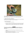
DELKRO TOP ED ISTALLATIO ISTRUCTIOS
PART UMBERS – D3300/ D3301/ D3302/ D3303/ D3304/ D3305/
D3310/ D3311/ D3312/ D3313/ D3414/ D3415/ D3062/ D3063/ D3064/
D3065
OTICE: If you are not experienced in engine building or do not feel confident in
performing this upgrade; STOP and consult an experience engine builder or shop!
These heads will accommodate up to .640 lift cams, but it is the engine
builder’s responsibility to check all related clearances.
1. Valve to valve clearances at TDC openings.
2. Valve to piston clearances.
WARIG! Incorrect installation of this kit could result in bodily harm,
death, and or property damage.
CAUTIO!
Use of adjustable pushrods is strongly recommended when installing these
performance kits.
CAUTIO!
Many issues can result from reusing o-rings some of which could be, low oil
pressure and oil leakage. Always use new o-rings and make sure they are in the
appropriate locations.
1. Piston ring end gap
Correct piston ring end gap is necessary for proper engine running.
With cylinders removed from engine and on work bench, install piston into bore of
cylinder, install one compression ring at a time into the top of the cylinder 1.00” below
the top of the cylinder bore, using the piston to assure that the compression ring is
“Square” to the bore … measure end gap.
Correct top compression ring and secondary compression ring end gap is equal to .004”
per inch of cylinder bore … example: 4.125” x .004” = .0165” of ring end gap. Rounding
this number to the next highest number is permissible … example: .0165” rounds to .017”
DO OT round to the next lowest number … example: .0165” to .016”. It is better to be
slightly larger with your ring end gap than smaller. Insufficient clearance on the
compression rings can lead to “Ring Abutment” at operating temperature while under
compression causing irreparable engine damage.
To achieve correct ring end gap when ring end gap is insufficient, too small, grinding of
the ring ends will be necessary. This can be done several different ways (File / Bench
Grinder / Ring Grinder / Etc.), but it is recommended that a ring grinding tool be used.
After grinding of ring be sure to deburr the ring ends prior to re-installing them into the
cylinder bore.
It is very important that the ring ends are square when installed into the cylinder bore.
Ring end gaps that are not square will lead to incorrect ring end gaps that can lead to
undesirable engine operation / function as well as irreparable engine damage.
2. Engine Reassembly and Installation
Reassemble cylinders and reinstall them as per your service manual instructions, making
sure that all parts are thoroughly cleaned prior to reassembly.
3. Install Cylinder Heads
A. Place the head gasket over the dowels.
B. Note that the letter F or R is cast into the top of the cylinder head to ensure proper
installation. Carefully set the cylinder head over the two dowels in the cylinder
head mating surface. Be careful not to drag the gasket surface across the dowels.
CAUTIO!
Thoroughly clean and lubricate the threads of the cylinder head bolts prior to
installation. Dirt, grime, and dry interfaces can cause friction, resulting in false
torque values.
C. Lightly coat the threads and bottom flange of the head bolts with clean light
engine oil.
D. Start the head bolts onto the cylinder studs, the 2 short bolts on the left side of the
engine and the longer bolts on the right side.
E. Tighten the head bolts as per the appropriate service manual.
CAUTIO!
Improperly tightened cylinder head bolts may result in gasket leaks, stud failure
and distortion of the cylinder head and/or cylinder.
F. Install a new rocker housing gasket on the cylinder head mating surface.
OTICE: If using OEM/ stock rocker boxes they must be modified to install the
breather channel using the enclosed template as described in the otice and Caution
sheet.
CAUTIO!
Because of high lift valve spring packs, clearance to rocker housings should be
checked. There should be .025 minimum clearance to spring retainers.
CAUTIO!
Be careful! Rocker housing to cylinder head gaskets can be installed upside down
and still have proper bolt hole alignment. An upside down gasket will result in an
open breather channel which will cause a major oil leak when the engine is started
and possibly engine and/or property damage.
G. Verify that the rocker housing gasket is correctly installed by noting that the
breather passage is concealed. Check hole alignment with cylinder head. With the
indent facing forward, place the rocker housing into position aligning the holes in
the housing with the holes in the gasket.
H. Apply a small amount of medium strength threadlocker 242/243 (blue) to the
threads of the six rocker housing bolts. Start the rocker housing bolts, two long
bolts on the left side of the engine, four intermediate bolts in the interior. Install
rocker arm support plate into rocker housing and start the four mounting bolts
(with flat washers). Two short bolts on the left side of engine, two long bolts on
the right. Alternately tighten the rocker housing bolts to 10-14 ft/lbs as shown in
the appropriate service manual.
I. Install new o-ring in the groove around the breather baffle hole in rocker housing.
A thin film of engine oil is recommended during installation.
J. Install pushrods and pushrod tubes as per service manual. Make sure o-rings are
in place and seated.
K. When installing the rocker arms for the cylinder being serviced, both lifters for
that cylinder should be on the heel (lowest position) of the cam.
L. Following the pattern shown in the appropriate service manual alternately tighten
each of the four rocker arm support mounting bolts until snug. Then following the
same numerical sequence; torque the bolts to 15-18 ft/lbs.
M. Verify that pushrods spin freely.
CAUTIO!
Rotating the engine with the valve train loaded can result in bent pushrods or
valve damage.
N. If using adjustable pushrods; adjust pushrods as per the manufacturer’s
instructions.
O. Install the two breather cover and baffle bolts. Alternately tighten bolts to 90-120
in/lbs.
P. Install a new rocker cover gasket and place rocker cover in position, making sure
that all the holes are in alignment.
Q. Apply a small amount of medium strength threadlocker 242/243 (blue) to the
threads of the six rocker cover bolts. Start the cover bolts, the three short bolts on
the left side of the engine, three long bolts on the right. Torque bolts to 9-12 ft/lbs.
using the pattern shown in the appropriate service manual.
R. Finish final assembly as per service manual.
S. HAVE FU!
THANK YOU FOR CHOOSING DELKRO IC. FOR YOUR HIGH
PERFORMANCE ENGINE NEEDS