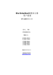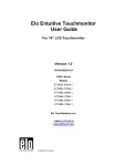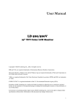
1
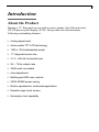
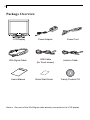
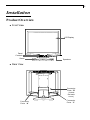
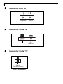
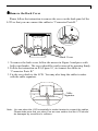
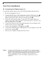
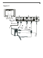
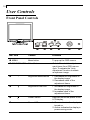
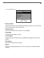
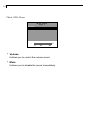
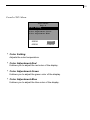
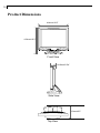
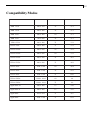
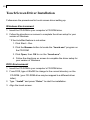
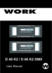
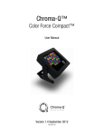
PLANAR LCD MONITOR PT170MU MANUAL www.planar.com 1 Table of Contents Usage Notice Precautions ................................................................................. 2 Introduction About the Product ....................................................................... 3 Package Overview ...................................................................... 4 Installation Product Overview ........................................................................ 5 Start Your Installation .................................................................. 8 User Controls Front Panel Controls ................................................................... 10 How to Use the OSD Menus ....................................................... 11 On-Screen Display Menus .......................................................... 12 Appendix Troubleshooting ........................................................................... Warning Signal ............................................................................ Product Dimensions .................................................................... Compatibility Modes ................................................................... Touch Screen Driver Installation ................................................. 16 17 18 19 20 2 Usage Notice Warning- To prevent the risk of fire or shock hazards, do not expose this product to rain or moisture. Warning- Please do not open or disassemble the product as this may cause electric shock. Precautions Follow all warnings, precautions and maintenance as recommended in this users manual to maximize the life of your unit. Do: q q q q q Turn off the product before cleaning. Use only a dry soft cloth or clean room wiper when cleaning the LCD panel surface. Use a soft cloth moistened with mild detergent to clean the display housing. Use only high quality and safety approved AC/DC power adapter. Disconnect the power plug from AC outlet if the product is not used for a long period of time. Dont: q q q Do not touch the LCD panel surface with sharp or hard objects. Do not use abrasive cleaners, waxes or solvents for your cleaning. Do not operate the product under the following conditions: - Extremely hot, cold or humid environment. - Areas susceptible to excessive dust and dirt. - Near any appliance generating a strong magnetic field. - Place in direct sunlight. 3 Introduction About the Product Having a 17 flat panel screen with an active matrix, thin-film transistor (TFT) liquid crystal display (LCD) , this product also demonstrates following outstanding features. q Analog signal input q Active matrix TFT LCD technology q 1280 x 1024 addressable pixels q 17 diagonal screen size q 31.5 ~ 80 kHz horizontal scan q 56 ~ 75 Hz refresh rate q VESA wall mountable q Auto-adjustment q Multilingual OSD user controls q VESA DPMS power saving q Built-in speakers for multimedia application q Resistive type touch screen q Kensington lock capability 4 Package Overview LCD Display VGA Signal Cable Users Manual Power Adapter USB Cable (for Touch screen) Quick Start Guide Power Cord Audio-In Cable Family Product CD Notice: One end of the VGA Signal cable already connected to the LCD display. 5 Installation Product Overview u Front View LCD Display Panel Controls Stand u Speakers Rear View Connector Ports B ( Inside the back cover) Connector Ports A Connector Ports C 6 u Connector Port A Headphone u Connector Ports B VGA input u Audio-In Connector Ports C USB In (For Touch Screen) Touch Function DC Power-In 7 uRemove the Back Cover Please follow the instruction to remove the cover on the back panel of the LCD so that you can connect the cables in Connector Ports B. A Back Cover 1. To remove the back cover, follow the arrows in Figure A and press with both your thumbs. The cover should be easily removed by pressing firmly. 2. Follow the instruction on P.9 (Figure 9.1) to connect the cables in Connector Ports B. 3. Fix the cover back to the LCD. You may also keep the cables in order with the cable organizer. Cable Organizer Note: You can place the LCD horizontally to make it easier to connect the cables. Please make sure that you place it on an even surface lest the LCD should be damaged by scratches or collision. 8 Start Your Installation u Connecting the Display (Figure 9.1) To setup this display, please refer to the following figure and procedures. 1. Be sure all equipment are off. 2. Connect the DC power cord to the power connector (The arrow sign must face down); plug one end of the AC power cord into the power adapter, and then the other end into an electrical outlet(). 3. For the PC with Analog output: Connect the VGA signal cable from display VGA input connector to the 15-pin connector of your host com puter and tighten the screws(). 4. Connect the Audio-In cable from audio input port of your display to the Audio-out port of your computer(). 5. Connect your headphone to Headphone port(). 6. Connect the USB cable from USB input port of your display to the USB port of your computer(). 7. Turn on your computer, display and video source. Notice: To ensure the LCD display can work well with your computer, please configure the display mode of your graphic card to make it less than or equal to 1280 x 1024 resolution and make sure timing of the display mode is compatible with the LCD display. We have listed the Compatibility Modes of this LCD display in appendices for your reference. 9 Figure 9.1 A C B Headphone Audio-In Cable VGA Cable Power Adapter & Power Cord USB cable 10 User Controls Front Panel Controls No./ Icon Control Function MENU Menu button To pop up the OSD menus. SELECT/AUTO Select/Auto Select- To select the adjustment items from OSD menus. Auto- To activate the Auto Adjustment function to obtain an optimum image. 3 Brightness Minus/Minus 1. Decreases the brightness of the display image. 2. Decreases value of the adjustment items. 4 Brightness Plus/Plus 1. Increases the brightness of the display image. 2. Increases value of the adjustment items. Power Switch Switches on/off the power of the LCD display. Power LED 1. Green indicates the display is turned on. 2. Amber indicates the display in power-saving mode. 11 How to Use the OSD Menus 1. Press the Menu button to pop up the on-screen menu and to select between the four Main Menus. 2. Choose the adjustment items by pressing the Select/Auto button. 3. Adjust the value of the adjustment items by pressing the 3 or 4 button. 4. Once you dont operate the OSD menus after a pre-set time, the OSD menus will automatically disappear. 12 On-Screen Display Menus First OSD Menu: Main Menu Page 1 Auto-Adjustment Contrast Horizontal Position Vertical Position Frequency Tracking No Yes 4 Auto-Adjustment Choose this function to obtain an optimum image. 4 Contrast Adjusts the contrast of the display image. 4 Horizontal Position Changes the horizontal position of the image. 4 Vertical Position Changes the vertical position of the image. 4 Frequency Changes the display data frequency to match the frequency of your graphic card. When you are experiencing vertical flickering bar, use this function to make an adjustment. 4 Tracking Synchronizes the signal timing of the display to that of the graphic card. When you are experiencing unstable to flickering image, use this function to make an adjustment. 13 Second OSD Menu: Main Menu Page 2 Display Mode OSD Off-Time Language Text-Graphic Sharpness Reset 1280* 1024 +) FH: 80 kHz (+ +) FV: 75 Hz (+ 4 Display Mode Selects this function to demonstrate the display resolution, vertical refresh, and horizontal scan of the current mode. 4 OSD Off-Time Adjusts the time period for OSD menu to disappear. 4 Language Chooses the language you need. 4 Text-Graphic Toggles between VGA text mode (mode M03H) and graphic mode (mode M13H). 4 Sharpness Adjust the sharpness of the image. 4 Reset Returns the display parameters of the current mode to its factory default settings. 14 Third OSD Menu: Vo l u m e Mute - 0 Main Menu Page 3 20 40 + 4 Volume It allows you to control the volume sound. 4 Mute It allows you to disable the sound immediately. 15 Fourth OSD Menu: Color Color Color Color Main Menu Page 4 Setting Adjustment-Red Adjustment-Green Adjustment-Blue 9300K 6500K Preset Custom 4 Color Setting Adjusts the color temperature. 4 Color Adjustment-Red It allows you to adjust the red color of the display. 4 Color Adjustment-Green It allows you to adjust the green color of the display. 4 Color Adjustment-Blue It allows you to adjust the blue color of the display. 16 Appendix Troubleshooting If you are experiencing trouble with the LCD display, refer to the following. If the problem persists, please contact your local dealer or our service center. Problem: No image appears on screen. 4 Check that all the I/O and power connectors are correctly and well connected as described in the Installation section. Make sure the pins of the connectors are not crooked or broken. 4 Problem: Partial image or incorrectly displayed image. 4 Check to see if the resolution of your computer is higher than that of the LCD display. 4 Reconfigure the resolution of your computer to make it less than or equal to 1280 x 1024. Problem: Image has flickering vertical line bars. 4 Use Frequency to make an adjustment. 4 Check and reconfigure the display mode of the vertical refresh rate of your graphic card to make it compatible with the LCD display. Problem: Image is unstable and flickering 4 Use Tracking to make an adjustment. Problem: Image is scrolling 4 Check and make sure the VGA signal cable (or adapter) is well connected. 4 Check and reconfigure the display mode of the vertical refresh rate of your graphic card to make it compatible with the LCD display. Problem: Vague image (characters and graphics) 4 Use Frequency to make an adjustment. If this problem still exists, use Tracking to make an adjustment. 17 Warning Signal Sometimes you probably will see the warning messages from this LCD screen. This means that the LCD display cannot exactly receive the signal from the computer graphic card. There are three kinds of situations that may happen. Please check the cable connections or contact your local dealer for more information. 4No Signal This message means that the LCD display has been powered on but it cannot receive any signal from the computer graphic card. Check all the power switches, power cables, and VGA signal cable. 4Going to Sleep This message means that the LCD display is under the power saving mode. In addition, the LCD display will go to this sleeping mode when experiencing a sudden signal disconnecting problem. 4Unsupport Mode This message means that the signal of the computer graphic card is not compatible with the LCD display. When the signal is not included in the compatibility mode we have listed in the Appendices of this manual, the LCD display will appear this message. 18 Product Dimensions 414mm/16.3 412mm/16.2 Front View 64.6mm/2.54 Side View 210mm/8.3 Top View 19 Compatibility Modes IBM VGA 640 x 350 70 31.5 IBM VGA 640 x 400 70 31.5 IBM VGA 640 x 480 60 31.5 IBM VGA 720 x 400 70 31.5 VESA VGA 640 x 480 72 37.9 VESA VGA 640 x 480 75 37.5 VESA SVGA 800 x 600 56 35.2 VESA SVGA 800 x 600 60 37.9 VESA SVGA 800 x 600 72 48.1 VESA SVGA 800 x 600 75 46.9 VESA XGA 1024 x 768 60 48.4 VESA XGA 1024 x 768 70 56.5 VESA XGA 1024 x 768 75 60.0 VESA SXGA 1280 x 1024 60 64 VESA SXGA 1280 x 1024 75 80 Apple Mac LC 640 x 480 67 34.9 Apple Mac II 640 x 480 67 35.0 Apple Mac 832 x 624 75 49.7 Apple Mac 1024 x 768 75 60.2 20 Touch Screen Driver Installation Follows are the procedures for touch screen driver setting up. Windows Environment 1. Insert the CD-ROM in your computers CD-ROM drive. 2. Follow the directions on screen to complete the driver setup for your version of Windows. * If the AutoStart feature is not active: 1. Click Start > Run 2. Click the Browse button to locate the touch.exe program on the CD-ROM. 3. Click Open, then OK to run the touch.exe. 4. Follow the directions on screen to complete the driver setup for your version of Windows. DOS Environment 1. Insert the CD-ROM in your computers CD-ROM drive. 2. From DOS, type d:\EloDW to change to the correct directory on the CD-ROM ( your CD-ROM drive may be mapped to a different driver letter). 2. Type Install and press Enter to start the installation. 3. Align the touch screen. M-F, 8am - 9pm Eastern Time 3/2003 03/03