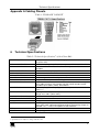
1
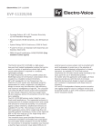
Kramer Electronics, Ltd.
USER MANUAL
Model:
Cobra DA9
1:9 CAT 5 Distributor
Contents
Contents
1
2
3
4
4.1
5
6
Introduction
Getting Started
Overview
Setup and Installation
Making the Connections
Solutions to Common Problems
Technical Specifications
1
1
2
3
3
4
5
Figures
Figure 1: Transmitter to Receiver Connections
3
Tables
Table 1: T568B CAT 5 PINOUT
Table 2: Technical Specifications of the Cobra DA9
5
5
i
Introduction
1
Introduction
Welcome to Kramer Electronics (since 1981): a world of unique, creative and
affordable solutions to the infinite range of problems that confront the video,
audio and presentation professional on a daily basis. In recent years, we have
redesigned and upgraded most of our line, making the best even better! Our
500-plus different models now appear in 8 Groups1, which are clearly defined
by function.
Congratulations on purchasing your Kramer Cobra DA9 1:9 CAT 5
Distributor. The Kramer Cobra Series System extends video signals over
ordinary CAT 5e cable. All models use a transmitter-to-receiver setup.
This manual covers the Cobra DA9 1:9 CAT 5 Distributor. A Kramer Cobra
transmitter unit as well as Kramer Cobra receiver units are required for
operation. Contact technical support for help.
The package includes the Cobra DA9 1:9 CAT 5 Distributor, a ground wire,
an external power supply (100–250 VAC, 50–60 Hz, autosensing) with cord, and
this user manual2.
The Kramer Cobra series products are not compatible with Kramer non-Cobra
series products.
2
Getting Started
We recommend that you:
Unpack the equipment carefully and save the original box and packaging
materials for possible future shipment
Review the contents of this user manual
Use Kramer high performance high resolution cables3. You may
also need CAT 5 cable
1 GROUP 1: Distribution Amplifiers; GROUP 2: Video and Audio Switchers, Matrix Switchers and Controllers; GROUP 3:
Video, Audio, VGA/XGA Processors; GROUP 4: Interfaces and Sync Processors; GROUP 5: Twisted Pair Interfaces;
GROUP 6: Accessories and Rack Adapters; GROUP 7: Scan Converters and Scalers; and GROUP 8: Cables and Connectors
2 Download up-to-date Kramer user manuals from the Internet at this URL: http://www.kramerelectronics.com
3 The complete list of Kramer cables is on our Web site at http://www.kramerelectronics.com
1
Overview
3
Overview
Our Kramer Cobra series products are compatible with CAT 5/5e/6 data
cabling as well as skew free CAT 5/5e cabling manufactured for video
applications. Note that some skew free CAT 5 is specific to a particular
vendor and is not compatible with our products. Ensure any skew free CAT 5
cable is non-proprietary prior to purchase / installation.
We recommend using our Kramer Cobra ultra low skew cable—BC-HDTP
(solid bulk) or BCP-HDTP (solid plenum bulk)—available in lengths of 700'
(210m) and 1300' (390m).
CAT 6 cable, due to the manufacture method, can exhibit much greater skew
than standard CAT 5/5e and may require skew compensation beyond what the
standard product offers. Contact Kramer Electronics for assistance.
CAT 5/5e/6 cabling for this product must be pinned to the TIA-EIA T568B
wiring specification (see appendix A). We also highly recommend that all
CAT 5 cables be pre-terminated and tested. Cables terminated on-site or in an
existing infrastructure should be tested before use to ensure compliance with
the TIA-EIA T568B specification. Using incorrectly terminated CAT 5 cables
can damage this product.
Achieving the best performance means:
Connecting only good quality connection cables, thus avoiding
interference, deterioration in signal quality due to poor matching, and
elevated noise levels (often associated with low quality cables)
Avoiding interference from neighboring electrical appliances that may
adversely influence signal quality and positioning your Cobra DA9 in a
location free from moisture and away from excessive sunlight and dust
Caution – No operator-serviceable parts inside unit.
Warning – Use only the Kramer Electronics input power
wall adapter that is provided with this unit1.
Warning – Disconnect power and unplug unit from wall
before installing or removing device or servicing unit.
Warning –This equipment is not intended for, nor does it
support, distribution through an Ethernet network. Do not
connect these devices to any sort of networking or
telecommunications equipment!
1 For example: model number AD2512C, part number 2535-000251
2
KRAMER: SIMPLE CREATIVE TECHNOLOGY
Setup and Installation
4
Setup and Installation
The Cobra DA9 utilizes industry standard CAT 5 cabling to connect a Cobra
transmitter and receivers. Additional Cobra DA9 distribution amplifiers may
be cascaded via the UTP Loop output or any other output if necessary.
4.1 Making the Connections
Figure 1 shows how to connect the Cobra DA9 distribution amplifier.
1. Connect the RJ-45 cable from a Cobra transmitter unit or other Cobra
DA9 distribution amplifier into the port labeled UTP IN.
2. Connect RJ-45 cables from Cobra receiver units into the ports labeled
OUTPUTS.
3. The port labeled UTP Loop may be used to cascade to other Cobra DA9
distribution amplifiers or can be used with a Cobra receiver.
4. Connect the power supply to the unit.
5. Connect the supplied ground cable to the rear gold thumbscrew and the other
end to a suitable earth ground. The grounding is required in instances where
LCD monitors are used that do not provide a ground via the DC power
adapter. Failure to connect the ground cable may result in loss of video signals.
With regard to connecting the cables:
We recommend mounting and connecting all cabling to the Cobra DA
Video / RS-232 Transmitter components before applying power.
Be sure that the CAT 5 cable you intend to use has been tested to comply
with the T568B wiring specification (see Appendix A).
Figure 1: Transmitter to Receiver Connections
3
Solutions to Common Problems
5
Solutions to Common Problems
In most cases, nearly every issue with the Cobra series can be resolved by
checking the CAT 5 termination and making sure that it’s pinned to the
TIA/EIA 568B wiring specification. However, there may be other problems
that cause the system to not perform as it is designed. Below are solutions to
the most common installation errors.
Reference the appropriate user manual for the transmitter and receiver in use
for issues specific to these units.
No video signal at the transmitter local port or at the receiver.
Problem:
Solution:
Problem:
Solution:
Problem:
Solution:
4
Check that both units are powered.
Ensure receiver EQ adjustment is set correctly.
Make sure the CAT 5 cable is terminated correctly per the
TIA/EIA 568B wiring specification.
Is the display device powered on and functioning?
Check to ensure display settings (resolution, refresh rate, and so
on) are compatible with input signal.
Poor audio quality.
Powered speakers are required. Make sure speaker power is ON.
Check input source levels from the source device. Make sure the
audio source is not overdriven or underdriven.
Audio is summed left and right for “A” versions. If using a single
channel, both audio inputs must be connected at the transmitter
end for full audio gain. Audio is line level.
SA serial//audio units support full stereo line level. A high
frequency noise may be heard if the CAT 5 cable from the
transmitter is disconnected, or the transmitter is not powered up.
This is normal and will disappear once a complete link connection
is made.
Serial communication doesn’t work correctly.
Are the serial devices connected properly? Are the serial
parameters correct for source/destination devices?
When using RS-232 transmitters or receivers in daisy chains, CAT
5 switches or Cobra DA , or Multi-output transmitters, the serial
signal is a unidirectionally broadcast mode only.
KRAMER: SIMPLE CREATIVE TECHNOLOGY
Technical Specifications
Appendix A Cabling Pinouts
Table 1: T568B CAT 5 PINOUT
6
Technical Specifications
1
Table 2: Technical Specifications of the Cobra DA9
CABLE REQUIRED:
Between transmitter and receiver(s): Category 5 shielded or unshielded twisted
pair (STP or UTP)
VIDEO COMPATIBILITY:
RGBHV, RGsB, composite (NTSC, PAL), component, HDTV, Y/C, YUV, s-video
AUDIO COMPATIBILITY:
Line-level combined L and R, stereo, or SPDIF digital, transmitter/receiverdependent
SERIAL COMPATIBILITY:
Uni-directional RS-232 (simplex), DC to 115k baud
COMPLIANCE:
CE; FCC Class A, IC Class A
VIDEO SUPPORT:
Transparent to users—transmitter/receiver dependent.
RESOLUTION AND REFRESH RATE: 1920 x 1200 @ 60 Hz receiver dependent
TRANSMISSION:
Transparent to users (automatic, no delay).
MAXIMUM DISTANCE:
Total end to end, from source device to farthest destination device, over good
CAT 5 cable (assuming source outputs signal at normal strength) receiver
dependent: Up to 1300 ft. ( 396m) all resolutions.
CONNECTORS:
(1) RJ-45 input, (9) RJ-45 output; (1) rear-mounted power inlet; max number of
9D tiers = 3
TOLERANCE:
Operating: 32 to 104°F (0 to 40°C);
Storage: -4 to +140°F (-20 to +60°C).
HUMIDITY TOLERANCE:
Up to 80% noncondensing
OPERATING / STORAGE TEMP.: 0 to 40°C / -20 to 60°C
ENCLOSURE:
Steel (powder-coated Galvanneal, for corrosion protection)
POWER:
From utility-power (mains) outlet to power inlet, through detachable external
power supply: Input: 100 to 250 VAC@ 50 or 60 Hz (autosensing); Output: 5V
regulated, + 3%, < 1.75A; Consumption: 12 watts maximum
SIZE:
1.75" H x 8.1" W x 6.5" D (4.45 x 21 x 16.5 cm)
WEIGHT:
2.2 lb. (1.0 kg)
1 Specifications are subject to change without notice
5
6
KRAMER: SIMPLE CREATIVE TECHNOLOGY
For the latest information on our products and a list of Kramer
distributors, visit our Web site: www.kramerelectronics.com,
where updates to this user manual may be found.
We welcome your questions, comments and feedback.
Safety Warning:
Disconnect the unit from the power supply before
opening/servicing.
Caution
Kramer Electronics, Ltd.
Web site: www.kramerelectronics.com
E-mail: [email protected]
P/N: 2900-650001 REV 3