1
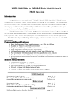
Kramer Electronics, Ltd.
USER MANUAL
Models:
Cobra R1300A, Video / Audio Receiver
Cobra R1300S2, Universal Receiver
Contents
Contents
1
2
3
4
4.1
4.2
4.3
4.4
4.5
Introduction
Getting Started
Overview
Setup and Installation
Data Mode Configuration
Making the Connections
Connections on the Single-Port VGA/Audio
Connections on the single-port VGA S2
Video Adjustment
1
2
2
4
4
4
5
6
7
4.5.1
4.5.2
Cable Distance Compensation Settings
Skew Compensation Settings
7
7
5
6
Solutions to Common Problems
Technical Specifications
8
16
Figures
Figure 1: Transmitter Connections
Figure 2: Cobra R1300A Video / Audio Receiver Connections
Figure 3: Transmitter Connections
Figure 4: Cobra R1300S2 Universal Receiver Connections
Figure 5: Adjustment locations
Figure 6: Skew Module
5
5
6
6
7
15
Tables
Table 1: HD15 Video Connector PINOUT
Table 2: Terminal Block Connection
Table 3: HD15 Video Connector PINOUT
Table 4: T568B CAT5 PINOUT
Table 5: Configuration Jumper Settings
Table 6: Technical Specifications of the Cobra R1300A, Cobra R1300S2
10
10
11
11
13
16
i
Introduction
1
Introduction
Welcome to Kramer Electronics (since 1981): a world of unique, creative and
affordable solutions to the infinite range of problems that confront the video,
audio and presentation professional on a daily basis. In recent years, we have
redesigned and upgraded most of our line, making the best even better! Our
500-plus different models now appear in 8 Groups1, which are clearly defined
by function.
Congratulations on purchasing your Kramer Cobra R1300A Video / Audio
Receiver and/or Cobra R1300S2 Universal Receiver. The Kramer Cobra
Series System extends video, audio and serial signals over ordinary Category
5 cable. This manual covers the Cobra R1300A Video / Audio Receiver, and
the Cobra R1300S2 Universal Receiver. These units are field configurable for
various video, audio and serial options. See Appendix B for configuration
settings. A versions support video and audio. S2 series feature video, stereo
audio and RS-232 signals on a single CAT 5.
The Kramer Cobra R1300A Video / Audio Receiver and Cobra R1300S2
Universal Receiver feature optional integrated skew compensation that can be
varied in 2 ns increments to 65 ns total per color channel to cancel the effects
of skew in Category cables. This feature allows you to use CAT5e and
reduced-skew CAT6 cables to lengths up to 1300ft. For information on the
respective transmitter unit, refer to the appropriate manual included with the
transmitter.
All models support refresh rates/resolutions up to 1920 x 1200 @ 60 Hz to
1300feet (396m).
The package includes the Cobra R1300A Video / Audio Receiver or the Cobra
R1300S2 Universal Receiver, an external power supply, and this user manual2.
The Kramer Cobra series products are not compatible with Kramer non-Cobra
series products.
1 GROUP 1: Distribution Amplifiers; GROUP 2: Video and Audio Switchers, Matrix Switchers and Controllers; GROUP 3:
Video, Audio, VGA/XGA Processors; GROUP 4: Interfaces and Sync Processors; GROUP 5: Twisted Pair Interfaces;
GROUP 6: Accessories and Rack Adapters; GROUP 7: Scan Converters and Scalers; and GROUP 8: Cables and Connectors
2 Download up-to-date Kramer user manuals from the Internet at this URL: http://www.kramerelectronics.com
1
Getting Started
2
Getting Started
We recommend that you:
Unpack the equipment carefully and save the original box and packaging
materials for possible future shipment
Review the contents of this user manual
Use Kramer high performance high resolution cables1. You may
also need CAT5 cable2
3
Overview
Our Kramer Cobra series products are compatible with CAT5/5e/6 data
cabling as well as skew free CAT5/5e cabling manufactured for video
applications. Note that some skew free CAT5 is specific to a particular
vendor and is not compatible with our products. Ensure any skew free CAT5
cable is non-proprietary prior to purchase / installation.
We recommend using our Kramer Cobra ultra low skew cable—BC-HDTP
(solid bulk) or BCP-HDTP (solid plenum bulk)—available in lengths of 700'
(210m) and 1300' (390m).
CAT6 cable, due to the manufacture method, can exhibit much greater skew
than standard CAT5/5e and may require skew compensation beyond what the
standard product offers. Contact Kramer Electronics for assistance.
CAT5/5e/6 cabling for this product must be pinned to the TIA-EIA T568B
wiring specification (see appendix A). We also highly recommend that all
CAT5 cables be pre-terminated and tested. Cables terminated on-site or in an
existing infrastructure should be tested before use to ensure compliance with
the TIA-EIA T568B specification. Using incorrectly terminated CAT5 cables
can damage this product.
Achieving the best performance means:
Connecting only good quality connection cables, thus avoiding
interference, deterioration in signal quality due to poor matching, and
elevated noise levels (often associated with low quality cables)
Avoiding interference from neighboring electrical appliances that may
adversely influence signal quality and positioning your Cobra R1300A /
R1300S2 in a location free from moisture and away from excessive
sunlight and dust
1 The complete list of Kramer cables is on our Web site at http://www.kramerelectronics.com
2 In addition, you may also need audio cable with RCA jacks, serial cable with DB9 connectors, and video cable with HD15
connectors
2
KRAMER: SIMPLE CREATIVE TECHNOLOGY
Overview
Caution – No operator-serviceable parts inside unit.
Warning – Use only the Kramer Electronics input power
wall adapter that is provided with this unit1.
Warning – Disconnect power and unplug unit from wall
before installing or removing device or servicing unit.
Warning –This equipment is not intended for, nor does it
support, distribution through an Ethernet network. Do not
connect these devices to any sort of networking or
telecommunications equipment!
1 For example: model number AD2512C, part number 2535-000251
3
Setup and Installation
4
Setup and Installation
4.1 Data Mode Configuration
The serial signal is 3 wire TX, RX, GND and does not support full modem
signals. Baud rates for the S2 series are fixed at 9600. Simplex modes are
supported without jumper or other changes by simply using the TX signal only.
S2 units require no configuration.
4.2 Making the Connections
This section contains figures showing connections with the specific Cobra
R1300A / R1300S2 series models. In general, however, the connection and
setup procedure at both transmitter and receiver ends is as follows:
NOTE: all units must be the same type for all supported features to function
correctly. For example, a Cobra transmitter set for R/L summed audio must be
connected to an R1300A / R1300S2 set for R/L summed audio. Similarly, a
Cobra T2 cannot be used with an R1300A / R1300S2. Video modes may
function normally, but 4th pair options will not.
At the transmitter end (refer to the transmitter user guide):
1. Connect the source video to the Cobra Series transmitter video input port,
which is an HD15 connector labeled SOURCE IN or VIDEO IN.
2. If desired, attach a local monitor via the local monitor port to LOCAL
OUT.
3. Make your audio/serial connections via the audio connector or DB9
connector as appropriate.
4. Connect the CAT5 cable to the transmitter.
5. Apply power on the transmitter. The LED should light and, if there is a local
monitor attached, a video image should appear on the monitor’s screen.
At the receiver end:
1. Connect the VIDEO OUT HD15 connector to the display unit and attach
any audio (AUDIO/AUX I/O) or serial connections (RS-232) depending on
the model of the Cobra CAT5 Video System.
2. Connect the CAT5 cable to the LINK INPUT connection. If daisy chaining
units, connect the output CAT5 cable to the LINK OUTPUT connection.
3. Apply power. The LED should light and video should appear on the display
(make sure that the display is powered ON).
4. Adjust video levels and skew compensation.
5. Mount the R1300A / R1300S2 in a location that ensures the ventilation
holes and fan are not blocked.
4
KRAMER: SIMPLE CREATIVE TECHNOLOGY
Setup and Installation
With regard to connecting the cables:
We recommend mounting and connecting all cabling to the Cobra
R1300A / R1300S2 components before applying power.
Be sure that the CAT5 cable you intend to use has been tested to comply
with the T568B wiring specification (see Appendix A).
4.3 Connections on the Single-Port VGA/Audio
The single-port units with audio support video and audio signals over CAT5
cable. The audio signal is line-level summed Right/Left audio, and powered
speakers are required. You can also use the transmitters and receivers to make
video-only connections without audio. Figure 1 shows the Single-Port Cobra
CAT5 Video System with Audio Transmitter connections, and Figure 2
shows the receiver connections.
Figure 1: Transmitter Connections
Figure 2: Cobra R1300A Video / Audio Receiver Connections
5
Setup and Installation
4.4 Connections on the single-port VGA S2
The Single-Port Cobra CAT5 Video System series supports RS-232, video
and stereo audio signals over CAT5 cable. Serial signals are 3 wire RS232
(Tx, Rx, ground) and fixed at 9600 baud. Full 9 pin modem signals are not
supported. Note when using the Cobra 2/S2 series with a Cobra Cat5 DA or
CAT5 matrix switch, the serial is transmit only. There are no configuration
changes required to the units. The serial application in use should be changed
to transmit only. Audio is full stereo, line level. One or two separate channels
of mono audio may also be used. See the Figures below for cabling
connections.
Figure 3: Transmitter Connections
Figure 4: Cobra R1300S2 Universal Receiver Connections
6
KRAMER: SIMPLE CREATIVE TECHNOLOGY
Setup and Installation
4.5 Video Adjustment
4.5.1
Cable Distance Compensation Settings
To get the highest quality video signals from your Cobra CAT5 Video
System, follow the instructions and diagrams below:
NOTE: TURN KNOB SLOWLY DURING ADJUSMENT PROCEDURE. Turning
too fast may result in missing the proper EQ setting resulting in picture loss.
To Reset EQ and Skew values to 0, remove power from R1300A / R1300S2,
Push and hold EQ/Skew Knob in and re-apply power.
1. Display a test pattern consisting of a black box on a white background.
Push EQ/Skew knob in once so that the R/G/B LED is white.
2. Turn the EQ/Skew knob clockwise until the shadow next to the black box
just disappears. The brightness in the white area should be the same as the
white area above and below the black box. The Cable Length LEDs will
turn on for indicated cable distances. Starting from zero feet to 1,000 may
take some time. Continue turning the knob for best picture quality.
3. Press and release EQ/Skew knob until the R/G/B LED is off.
Figure 5: Adjustment locations
4.5.2
Skew Compensation Settings
The R1300A / R1300S2 receiver is available with an optional skew
compensation module to adjust for signal timing differences due to differing
pair lengths within the CAT5 cable. Using the delay signals, skew may be
compensated from 2 to 65 nanoseconds in 2 nanosecond increments on each
individual color pair. If skew compensation is required, but the skew comp
module is not installed, call for technical assistance.
1. To adjust individual colors, press the EQ/Skew knob until the desired
color LED is on for the R/G/B LED. The LED color corresponds to the
color channel being adjusted.
2. Using the image utility, turn knob to add/subtract delay timing until a
single vertically aligned line of red, green, blue is obtained.
3. When complete press EQ/Skew knob until R/G/B LED is off.
Not all colors will have the same delay settings.
7
Solutions to Common Problems
5
Solutions to Common Problems
In most cases, nearly every issue with the Cobra series can be resolved by
checking the CAT5 termination and making sure that it’s pinned to the
TIA/EIA 568B wiring specification. However, there may be other problems
that cause the system to not perform as it is designed. Below are solutions to
the most common installation errors.
Problem:
Solution:
Problem:
Solution:
Problem:
Solution:
Problem:
Solution:
8
No video signal at the transmitter local port or at the receiver
Check that both units are powered.
Ensure EQ adjustment is set correctly — turn knob slowly. • Make
sure the CAT5 cable is terminated correctly per the TIA/EIA 568B
wiring specification.
Is the display device powered on and functioning?
Check to ensure display settings (resolution, refresh rate, etc) are
compatible with input signal.
Poor video quality.
Have all receiver adjustments been finished?
Ensure EQ adjustment switches are set correctly
Check all cable connections
The video signal’s refresh rate may be set too high. Reset to a
lower refresh rate in your monitor-configuration menu
There may be a delay skew issue. See Section on Skew
Poor audio quality.
Powered speakers are required. Make sure speaker power is ON
Check input source levels from the source device. Make sure the
audio source is not overdriven or underdriven.
Audio is summed left and right for “A” versions. If using a single
channel, both audio inputs must be connected at the transmitter
end for full audio gain. Audio is line level
Serial//audio units support full stereo line level. A high frequency
noise may be heard if the CAT5 cable from the transmitter is
disconnected, or the transmitter is not on. This is normal and will
disappear once a complete link connection is made. Units do not
exhibit this behavior
Serial communication doesn’t work correctly.
Are the serial devices connected properly? Are the serial
parameters correct for source/destination devices?
Are the serial cables terminated correctly? If a null-modem cable
is used, it must be placed at the receiver end.
When using RS-232 transmitters or receivers in daisy chains,
CAT5 switches, CAT5 distribution amps, or Multi-output
transmitters, the serial signal is a unidirectionally broadcast mode
only. In this mode, all other Cobra CAT5 Video System devices
must be the simplex serial type.
The last device in a transmitter or daisy chain configuration must
be terminated. The termination switch is located on the front of
the unit.
KRAMER: SIMPLE CREATIVE TECHNOLOGY
Solutions to Common Problems
Problem:
Solution:
Problem:
Solution:
“Green shift” or “green washout” on multimedia signals.
The standard video/serial model is designed to function with DC
coupled signals in which the black level is referenced to 0 volts.
Nearly all VGA cards function this way. Some media servers,
however, provide AC coupled signals and can cause a green color
shift in the video. This is a result of the sync clamping on the red
and blue channels of the video/serial model. For five-component
(RGB/H&V) AC coupled video, the Cobra CAT5 transmitter has
been designed with full DC restoration capability. This problem is
easily solved via a simple switch setting in the Cobra Transmitter.
Refer to the Cobra Transmitter user manual.
Notes on Daisy Chaining:
When daisy chaining, the maximum cable distance is not
increased beyond the rated distance of the receiver used. For
example, the maximum distance from a transmitter to the last
R1300S2 Receiver in a daisy-chain is 1300 feet. A maximum of
12 units may be daisy chained together. If a unit in the middle of
the chain loses power or is disconnected from the chain, all units
after this will lose signals. All serial communication in a daisy
chain is one way simplex.
9
Solutions to Common Problems
Appendix A Cabling Pinouts
Table 1: HD15 Video Connector PINOUT
Pin
RGBHV
(VGA)
RGBS
RGsB
1
Red +
Red +
Red +
2
Green+
Green+
Green+
3
Blue+
Blue+
Blue+
4
—
—
—
5
Gnd
Gnd
Gnd
6
Red-
Red-
Red-
7
Green-
Green-
Green-
8
Blue-
Blue-
Blue-
9
—
—
—
10
Gnd
Gnd
—
11
Gnd
Gnd
—
12
—
—
—
13
H Sync
C Sync
—
14
V Sync
—
—
15
Gnd
Gnd
—
Composite SVHS
(Y/C)
C+
YUV
C+
V+
Y+
Y+
U+
C-
C-
V-
Y-
YU-
Table 2: Terminal Block Connection
PIN
Audio
Audio*
Simplex Serial
SPDIF Audio
Composite Video
Pin 1
Left Channel
Right Channel
Tx
Signal +
Signal +
Pin 2
Ground
Ground
ground
Signal -
Signal -
Pin 3
Right Channel
Left Channel
-
-
-
Pin 4
-
Shell
-
-
Note: Typically Channel 1 is left audio and Channel 2 is right audio.
* series RECEIVER units use Channel 1 for Right audio and channel 2
for left audio.
* series TRANSMITTER units use Channel 2 for Right audio and channel
1 for left audio.
10
KRAMER: SIMPLE CREATIVE TECHNOLOGY
Solutions to Common Problems
Appendix A Cabling Pinouts
Table 3: HD15 Video Connector PINOUT
Pin
Full Duplex
3 wire (SA/SAP)
Simplex
1
DCD
2
RX
RX
3
TX
TX
TX
4
DTR
5
Ground
Ground
Ground
6
DSR
7
RTS
8
CTS
9
RI
Table 4: T568B CAT5 PINOUT
11
Solutions to Common Problems
Appendix B Configuration Settings
Note: the Cobra R1300A Video and the Audio Receiver Cobra R1300S2
Universal Receiver are typically pre-configured at time of order and will have
factory configuration indicated on the bottom of the unit. The factory
configuration may be changed or checked by using the following jumper
location diagram as well as Table 5 for jumper settings.
12
KRAMER: SIMPLE CREATIVE TECHNOLOGY
Solutions to Common Problems
Table 5: Configuration Jumper Settings
Configuration Option (all options
utilize 4th pair):
SW1
JP1
JP2
JP3
SW2
JP4
1
2
3
4
5
1
2
RGBHV Computer Video (see note below on daisy chaining)
With Left/Right Line Level Audio
1-2
1-2
1-2
1-2
OFF
ON
ON
OFF
OFF OFF
OFF
With SDPIF Digital Audio
1-2
1-2
1-2
1-2
OFF
ON
OFF
OFF
OFF OFF
ON
With Simplex Serial (receive only)
1-2
1-2
1-2
1-2
ON
OFF OFF
OFF
OFF
ON
OFF
With Composite Video
1-2
1-2
1-2
1-2
OFF
ON
OFF
OFF
OFF OFF
ON
With RS 232 serial series (requires
separate daughterboard installed)**
Also set External TERM switch to
OFF.
2-3
2-3
2-3
2-3
OFF OFF OFF
OFF
OFF OFF
OFF
Composite, S-Video, Component Video (see note below on daisy chaining)
With Left/Right Line Level Audio
1-2
1-2
1-2
1-2
OFF
With SDPIF Digital Audio
1-2
1-2
1-2
1-2
With Simplex Serial (receive only)
1-2
1-2
1-2
1-2
With Composite Video
1-2
1-2
1-2
With RS 232 serial series (requires
separate daughterboard installed)**
Also set External TERM switch to
OFF.
2-3
2-3
2-3
ON
ON
OFF
OFF
OFF OFF
OFF
ON
OFF OFF
OFF
OFF
ON
ON
OFF OFF OFF
OFF
ON
OFF
1-2
OFF
ON
OFF OFF
OFF
OFF
ON
2-3
OFF OFF OFF OFF
OFF
OFF OFF
Dual Port Daisy Chain units
* For END OF LINE Units, use
configuration above, but set the
external TERM switch to ON.
*
*
*
*
*
*
*
*
*
*
*
*Middle daisy chain units, use
configuration above, but set the
external TERM switch to OFF.
*
*
*
*
*
*
*
*
*
*
*
** FOR series units in the middle of a
daisy chain, set external TERM
switch to OFF and note JP1/JP2
changes
1-2
1-2
*
*
*
*
*
*
*
*
*
13
Solutions to Common Problems
Appendix D Setting Sync Mode
The Cobra R1300A / R1300S2 has the capability for fixed and agile sync.
The default sync mode setting is for agile sync which replicates the source
sync polarity signals. However some displays require a fixed sync polarity
that is not possible to change at the video source.
The following details jumper settings to change the sync polarity of the
horizontal and vertical sync signals (note that jumpers JP6 and JP7 have no
affect in agile mode):
14
KRAMER: SIMPLE CREATIVE TECHNOLOGY
Solutions to Common Problems
Appendix E Skew Module
The Cobra R1300A / R1300S2 receivers have an optional skew
compensation module that can be installed or removed.
To install the skew compensation module:
1. Remove top cover.
2. Remove the 3 jumpers from J16 pins 1-2, 4-5, 7-8.
3. Insert the Skew assembly onto the PCB using 11 pin headers J16 and J17.
4. The correct orientation of the skew board is to place the side with the logo
into header J17.
5. Reassemble unit.
Removal is the opposite of the above. Ensure 3 jumpers are installed in
locations shown in Figure 6:
Figure 6: Skew Module
15
Technical Specifications
6
Technical Specifications
1
Table 6: Technical Specifications of the Cobra R1300A, Cobra R1300S2
CABLE REQUIRED:
COMPLIANCE:
VIDEO SUPPORT:
Category 5, 5e, 6 shielded or unshielded twisted pair
CE; FCC Class A, IC Class/class A
all supported VESA modes to WUXGA (1920x1200), RGBHV, RGB,
Composite (NTSC, PAL, SECAM), S-Video, Component Video,
widescreen modes, HDTV modes including 1080p, 1080i, 720p
At 1300 ft. or less: a maximum of 1920x1200 to 60 Hz
RESOLUTION AND REFRESH
RATE:
REQUIRED SOURCE IMPEDANCE: Video OUT: 75 ohms;
Audio OUT (if any): 600 ohms maximum
REQUIRED DESTINATION
Video IN: 75 ohms;
IMPEDANCE:
Audio models: Audio IN (if any): 600 ohms minimum
AUDIO CHARACTERISTICS:
Right/Left summed (A option)
SA/SAP: Full Stereo
Line Level 600 Ohm Unbalanced
SERIAL CHARACTERISTICS:
3 wire, fixed baud rate of 9600
CONNECTORS:
(1) 4 pin terminal block, (2) RJ-45, (1) HD15 F; (1) DB9M (model
dependent)
TEMPERATURE TOLERANCE:
Operating: 32 to 104°F (0 to 40°C);
Storage: -4 to +140°F (-20 to +60°C).
HUMIDITY TOLERANCE:
Up to 80% noncondensing
ENCLOSURE:
Steel
POWER:
+5 VDC @ 260 mA max
Consumption: 6 watts maximum
SIZE:
1.2" H x 4.1" W x 5.5" D (3.0 x 10.4 x 14.0 cm)
WEIGHT:
1.0 lb. (0.45 kg)
1 Specifications are subject to change without notice
16
KRAMER: SIMPLE CREATIVE TECHNOLOGY
17
For the latest information on our products and a list of Kramer
distributors, visit our Web site: www.kramerelectronics.com,
where updates to this user manual may be found.
We welcome your questions, comments and feedback.
Safety Warning:
Disconnect the unit from the power supply before
opening/servicing.
Caution
Kramer Electronics, Ltd.
Web site: www.kramerelectronics.com
E-mail: [email protected]
P/N: 2900-650004 REV 2