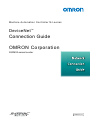
1
Machine Automation Controller NJ-series
DeviceNet
TM
Connection Guide
OMRON Corporation
3G3MX2-series Inverter
P522-E1-01
About Intellectual Property Right and Trademarks
Windows is a registered trademark of Microsoft Corporation in the USA and other countries.
DeviceNetTM is a trademark of ODVA.
EtherCAT® is registered trademark and patented technology, licensed by Beckhoff Automation
GmbH, Germany.
Company names and product names in this document are the trademarks or registered
trademarks of their respective companies.
Table of Contents
1.
Related Manuals .......................................................................................................... 1
2.
Terms and Definition ................................................................................................... 1
3.
Remarks ....................................................................................................................... 2
4.
Overview ...................................................................................................................... 4
5.
Applicable Devices and Support Software................................................................ 4
6.
7.
8.
9.
5.1.
Applicable Devices............................................................................................... 4
5.2.
Device Configuration............................................................................................ 6
DeviceNet Settings ...................................................................................................... 8
6.1.
DeviceNet Communications Settings ................................................................... 8
6.2.
Allocation of Remote I/O Communications........................................................... 8
Connection Procedure ...............................................................................................11
7.1.
Overview of Setting Up Remote I/O Communications.........................................11
7.2.
Work Flow .......................................................................................................... 12
7.3.
Setting Up the Inverter ....................................................................................... 13
7.4.
Setting Up the Controller.................................................................................... 21
7.5.
Setting Up the Network ...................................................................................... 28
7.6.
Connection Status Check................................................................................... 33
Initialization Method .................................................................................................. 38
8.1.
Controller ........................................................................................................... 38
8.2.
Inverter............................................................................................................... 39
Appendix 1 Details of Remote I/O Communication Settings .................................. 40
9.1.
Global Variable Table ......................................................................................... 40
10. Appendix 2 Setting Procedure without the Configuration Files............................ 41
10.1.
Overview of Setting Procedure without the Configuration Files ......................... 41
10.2.
Work Flow of the "Procedure for Setting the Parameters from the Beginning" .. 42
10.3.
Setting up the Controller without the Configuration Files ................................... 44
10.4.
Setting up the Network by CX-Integrator............................................................ 54
11. Revision History ........................................................................................................ 62
1. Related Manuals
1. Related Manuals
The table below lists the manuals related to this document.
To ensure system safety, make sure to always read and heed the information provided in all
Safety Precautions, Precautions for Safe Use, and Precaution for Correct Use of manuals for
each device which is used in the system.
Cat.No.
Model
Manual name
W500
NJ501-[][][][]
NJ-series CPU Unit Hardware User's Manual
W501
NJ501-[][][][]
NJ-series CPU Unit Software User's Manual
W497
CJ1W-DRM21
CJ-series DeviceNetTM Units Operation Manual for NJ-series
CPU Unit
W267
-
DeviceNetTM Operation Manual
W504
SYSMAC-SE2[][][]
Sysmac Studio Version 1 Operation Manual
W464
-
CX-Integrator CS/CJ/CP/NSJ-series Network Configuration
Tool Operation Manual
I570
3G3MX2-A[][][][]
SYSDRIVE MX2 Series Multi-function Compact Inverter
User's Manual
I581
3G3AX-MX2-DRT-E
MX2/RS Series DeviceNetTM Communications Unit User's
Manual
2. Terms and Definition
Terms
Master/slave
Explanation and Definition
A master is a unit that manages the DeviceNet communications.
A master sends output data to multiple slaves and receives input data from
the slaves.
Slaves receive output data that are sent from the master, and send input
data to the master.
At least one master is required for DeviceNet communications.
EDS file
A file that contains each DeviceNet slave's I/O points and parameters that
can be set via DeviceNet.
Node address
An address that identifies a unit connected to a DeviceNet network.
(MAC ID)
With DeviceNet, a MAC (Media Access Control) ID is used as a node
address. Thus, a node address is a MAC ID.
Scan list
A scan list is used to register slaves with which a master communicates in
DeviceNet remote I/O communications. A master communicates with the
slaves based on the scan list settings.
1
3. Remarks
3. Remarks
(1) Understand the specifications of devices which are used in the system. Allow some
margin for ratings and performance. Provide safety measures, such as installing safety
circuit in order to ensure safety and minimize risks for abnormal occurrence.
(2) To ensure system safety, always read and heed the information provided in all Safety
Precautions, Precautions for Safe Use, and Precaution for Correct Use of manuals for
each device used in the system.
(3) The users are encouraged to confirm the standards and regulations that the system must
conform to.
(4) It is prohibited to copy, to reproduce, and to distribute a part of or whole part of this
document without the permission of OMRON Corporation.
(5) This document provides the latest information as of February 2012. The information
contained in this document is subject to change for improvement without notice.
2
3. Remarks
The following notation is used in this document.
Precautions for Safe Use
Indicates precautions on what to do and what not to do to ensure using the product safely.
Precautions for Correct Use
Indicates precautions on what to do and what not to do to ensure proper operation and
performance.
Additional Information
Provides useful information.
Additional information to increase understanding or make operation easier.
3
4. Overview
4. Overview
This document describes the procedure for connecting the OMRON Inverter (3G3MX2 series)
to the OMRON Machine Automation NJ-series Controller (hereinafter referred to as
Controller) on the DeviceNet and provides the procedure for checking their connection.
This document describes the procedure for establishing a DeviceNet connection using
DeviceNet settings of the project files prepared in advance (hereinafter referred to as the
"procedures for using configuration files").
Sections 9 A-1 and 10 A-2 describe the procedures for setting parameters without the
prepared configuration files (hereinafter referred to as the "procedures for setting parameters
from beginning".
To follow the "procedures for using configuration files", obtain the latest "Sysmac Studio
project file" and "CX-Integrator project file" (they are referred to as "configuration files") from
OMRON in advance.
Name
Sysmac Studio project file
(extension: SMC)
CX-Integrator project file
(extension: cin)
File name
Version
OMRON_3G3MX2_DN_EV100.SMC
Ver.1.00
OMRON_3G3MX2_DN_EV100.cin
Ver.1.00
5. Applicable Devices and Support Software
5.1. Applicable Devices
The following devices can be connected.
Manufacturer
OMRON
OMRON
OMRON
OMRON
Name
NJ-series CPU Unit
DeviceNet Unit (Master Unit)
Inverter
DeviceNet Communications
Unit
Model
NJ501-[][][][]
CJ1W-DRM21
3G3MX2-A[][][][]
3G3AX-MX2-DRT-E
Version
Versions
listed in
Section 5.2
and higher
versions
Additional Information
As applicable devices above, the devices listed in Section 5.2. are actually used in this
document to check the connection. When using devices not listed in Section 5.2, check the
connection by referring to the procedure in this document.
4
5. Applicable Devices and Support Software
Additional Information
This document describes the procedure to establish the network connection. It does not
provide information about operation, installation nor wiring method of each device.
For details on above products (other than communication connection procedures), refer to
the manuals for the corresponding products or contact your OMRON representative.
Additional Information
You can connect devices with the versions listed in Section 5.2 or higher versions.
For devices whose versions are not listed in Section 5.2, versions are not managed or there
is no version restriction.
To connect a device whose model number is not listed in Section 5.2, use the same version
of the device that is listed.
5
5. Applicable Devices and Support Software
5.2. Device Configuration
The hardware components to reproduce the connection procedure of this document are as
follows.
Personal computer
(Sysmac Studio
installed,
OS:Windows7 )
3G3MX2-A2015 +
3G3AX-MX2-DRT
NJ501-1500+
CJ1W-DRM21
DeviceNet cable
USB cable
T-branch Tap (DCN1-1C)
Manufacturer
OMRON
OMRON
OMRON
OMRON
OMRON
OMRON
OMRON
OMRON
OMRON
OMRON
OMRON
Name
DeviceNet Unit
(Master Unit)
CPU Unit
Power Supply Unit
DeviceNet cable
T-branch Tap
Sysmac Studio
CX-Integrator
Sysmac Studio project file
CX-Integrator project file
Personal computer
(OS: Windows 7)
USB cable
(USB 2.0 type B connector)
Inverter
DeviceNet Communications
Unit
Model
CJ1W-DRM21
NJ501-1500
NJ-PA3001
DCA1-5C10
DCN1-1C
SYSMAC-SE2[][][]
(Bundled in the Sysmac Studio.)
OMRON_3G3MX2_DN_EV100.S
MC
OMRON_3G3MX2_DN_EV100.cin
-
Version
Ver.1.3
Ver.1.00
Ver.2.51
Ver.1.00
Ver.1.00
3G3MX2-A2015
3G3AX-MX2-DRT-E
Ver.1.1
Precautions for Correct Use
To use configuration files, prepare the latest "Sysmac Studio project file" and "CX-Integrator
project file" in advance.
(To obtain the files, contact your OMRON representative.)
Additional Information
For information on the DeviceNet cable and network wiring, refer to Section 2 Network
Configuration and Wiring in the DeviceNet Operation Manuel (Cat.No. W267).
Connect a terminating resistance to each end of the trunk line of the DeviceNet.
6
5. Applicable Devices and Support Software
Additional Information
In this document, a USB is used to connect with the Controller. For information on how to
install a USB driver, refer to A-1 Driver Installation for Direct USB Cable Connection of the
Sysmac Studio Version 1 Operation Manual (Cat.No. W504).
7
6. DeviceNet Settings
6. DeviceNet Settings
This section provides specifications such as communications parameters and variable names
that are defined in this document.
Hereinafter, the Inverter is referred to as "destination device" in some descriptions.
6.1. DeviceNet Communications Settings
The following are the settings for DeviceNet.
CJ1W-DRM21
Inverter
Unit number
0
-
Node address (MAC ID)
63
0
Baud rate (bps)
500 kbps
(Automatically sets the same
setting as for the Master Unit)
6.2. Allocation of Remote I/O Communications
The remote I/O communication data of the destination device are allocated to Controller's
global variables. An allocation of the remote I/O communication data is called a scan list. The
relationship between the device data and the global variables is shown below. The following
global variables are defined in "Configuration file".
■Output area (Controller → Inverter)
Destination device
Memory used
data
for CJ-series
Offset
Global variable name
Data type
Unit
+0
Command
+1
Rotation Speed
Reference
%3200
DN00_CMD_OUT
%3201
DN00_DATA_OUT
BOOL [16]
WORD
■Input area (Controller ← Inverter)
Destination device
Memory used
data
for CJ-series
Global variable name
Data type
Unit
Offset
+0
Status information
+1
Rotation Speed
Monitor
%3300
DN00_STA_IN
BOOL[16]
%3301
DN00_DATA_IN
WORD
8
6. DeviceNet Settings
Additional Information
When a DeviceNet Unit is used with a Controller, slave data are allocated to the memory
used for CJ-series Units. With programs, specify variable names for the memory used for
CJ-series Units.
With Sysmac Studio, add the prefix "%" to each address to indicate the memory used for
CJ-series Units.
■Details on output area
Global variable
Name
DN00_CMD_OUT[0]
FW
Forward/Stop
DN00_CMD_OUT[1]
RV
Reverse/Stop
DN00_CMD_OUT[2]
RS
Reset
DN00_CMD_OUT[5]
CTR
Net Ctrl.
DN00_CMD_OUT[6]
REF
Net Ref.
Description
0: Stop
1: Forward
0: Stop
1: Reverse
0: 1: Fault reset
0: Follow the setting of parameter A002.
1: Follow the reference from network control.
0: Follow the setting of parameter A001.
1: Follow the reference from network control.
If parameter P049 (Number of Poles for Rotation
Speed Setting) is set appropriately, the rotational
DN00_DATA_OUT
Rotation Speed
speed unit is [min -1].
Reference
If parameter P049 (Number of Poles for Rotation
Speed Setting) is set to 0, the frequency unit is [0.01
Hz].
9
6. DeviceNet Settings
■Details on input area
Global variable
Name
DN00_STA_IN[0]
AL
DN00_STA_IN[1]
WR
DN00_STA_IN[2]
FWR
Description
Alarm
0:Normal
output
1: Fault/Trip
Warning
0:Normal
1:Warning
During
0:During reverse run/Stopping
forward
1: During forward run
operation
DN00_STA_IN[3]
RVR
During
0:During forward run/Stopping
reverse
1:During reverse run
operation
DN00_STA_IN[4]
IRDY
DN00_STA_IN[5]
CFN
DN00_STA_IN[6]
RFN
DN00_STA_IN[7]
FA1
Operation
0:Not ready
ready
1:Ready
Ctrl. from
0:Follow the setting of parameter A002.
Net
1:DeviceNet reference
Ref. from
0:Follow the setting of parameter A001.
Net
1:DeviceNet reference
Constant
0:Accelerating or decelerating/Stopping
speed
1:Frequency agree
reached
DN00_STA_IN
DN00_STA_IN[8]
to
Drive Status
DN00_STA_IN[15]
[15] to [11]
[10]
[9]
[8]
1: Startup
0
0
0
1
2: Not ready
0
0
1
0
3: Ready
0
0
1
1
4: Operation in
0
1
0
0
5: Stopping
0
1
0
1
6: Fault/Trip stop
0
1
1
0
7: Fault/Trip
0
1
1
1
progress
If parameter P049 (Number of Poles for Rotation Speed
Setting) is set appropriately, the rotational speed unit is
DN00_DATA_IN
Rotation Speed
[min -1].
Monitor
If parameter P049 (Number of Poles for Rotation Speed
Setting) is set to 0, the frequency is monitored in units of
[0.01 Hz].
10
7. Connection Procedure
7. Connection Procedure
This section describes how to connect the Controller on the DeviceNet network using the
"procedures for using configuration files".
This document explains the procedures for setting up the Controller and Inverter from the
factory default setting. For the initialization, refer to Section 8 Initialization Method.
7.1. Overview of Setting Up Remote I/O Communications
The following shows the relationship of processes to operate DeviceNet remote I/O
communications using the "procedures for using configuration files".
Configuration files
Sysmac Studio
project file
CX-Integrator
project file
Importing
project file
Opening
project file
Personal computer
CX-Integrator
Sysmac Studio
Transferring
project data
Controller
Transferring
scan list
Destination
device
11
7. Connection Procedure
7.2. Work Flow
The following is the procedure for making connection settings for remote I/O communications
of DeviceNet.
7.3 Setting Up the Inverter
↓
7.3.1 Hardware Setting
Set up the Inverter (3G3MX2 series).
Mount the DeviceNet Communications Unit on the
Inverter.
↓
7.3.2 Parameter setting
↓
7.4 Setting Up the Controller
↓
7.4.1 Hardware Settings for the
DeviceNet Unit
↓
7.4.2 Starting the Sysmac Studio and
Importing the Project File
↓
7.4.3 Going Online and Transferring
the Project Data
↓
7.5 Setting Up the Network
↓
7.5.1 Starting the CX-Integrator and
Opening the Project File
↓
7.5.2 Going Online and Transferring a
Scan List
↓
7.6 Connection Status Check
↓
7.6.1 Checking the Connection Status
↓
7.6.2 Checking Data that are Sent and
Received
Set the parameter of the Inverter.
Set up the Controller.
Set the hardware switches on the DeviceNet Unit
and connect to the Controller.
Start the Sysmac Studio, and import the Sysmac
Studio project file.
Go online with the Sysmac Studio and transfer the
project data to the Controller.
Set up remote I/O communications of DeviceNet.
Start the CX-Integrator and open the CX-Integrator
project file.
Go online with the Controller, and transfer the
setting (scan list) of the set device to the DeviceNet
Unit via the Controller.
Check the status of the DeviceNet network
connection.
Confirm that the DeviceNet communication is
correctly performed.
Confirm that the correct data are sent and received.
Precautions for Correct Use
Obtain the latest "Sysmac Studio project file" and "CX-Integrator project file" from OMRON in
advance.
(To obtain the files, contact your OMRON representative.)
12
7. Connection Procedure
7.3. Setting Up the Inverter
Set up the Inverter (3G3MX2 series).
7.3.1.
Hardware Setting
Mount the DeviceNet Communications Unit on the Inverter.
Precautions for Correct Use
Make sure that the power supply is OFF when you perform the settings.
1
Confirm that the power supply to *If the power supply is turned ON, settings may not be
the Inverter is OFF.
applicable as described in the following procedure.
2
Refer to the right figure and
check the name of each part on
the DeviceNet Communications
Unit.
●Inverter
(3)Cooling fin
(4)Main housing
(5)Terminal block cover
(6)Optional board cover
(7)Backing plate
●DeviceNet Communications Unit
A- Communications Unit
connector
B-LED indicators (MS, NS)
C-Warning label
D-Fieldbus connector
E-Grounding cable
F-Housing
G-Mounting screw
13
7. Connection Procedure
3
Unscrew and remove the
optional board cover.
*For details on how to install the
DeviceNet Communications
Unit, refer to 2-2 Installation in
the DeviceNet Communications
Unit User's Manual (Cat.No.
I581).
4
Unscrew and remove the
terminal block cover.
5
Connect the Grounding Cable of
the DeviceNet Communications
Unit to the Inverter.
6
If the terminal block cover is
removed, mount it again and
tighten the screw.
1-phase 200 V 0.1 - 2.2 kW
3-phase 200 V 0.1 - 3.7 kW
3-phase 400 V 0.4 - 4.0 kW
3-phase 200 V 5.5 - 15 kW
3-phase 400 V 5.5 - 15 kW
14
7. Connection Procedure
7
Push the DeviceNet
Communications Unit at the
position of the optional cover
until it clicks into place.
8
Press down on the indicated
top-left corner of the DeviceNet
Communications Unit and
ensure the connector of the
DeviceNet Communications Unit
is properly connected.
9
Confirm that there is no gap
between the top edges of the
DeviceNet Communications Unit
and the Inverter casing.
10
Secure the DeviceNet
Communications Unit to the
Inverter with a mounting screw.
15
7. Connection Procedure
7.3.2.
Parameter setting
Set the parameters (node address) of the Inverter.
Additional Information
Make sure that the DeviceNet is not connected when you perform the settings.
1
Turn ON the power supply to the
Inverter.
*Set the parameters by using
the digital operator that is on
the front of the Inverter.
Display
Various parameters, frequency/set
value and other data are displayed
(red).
RUN key
Runs the Inverter. Take note that this
key is enabled only when the RUN
command destination is the Digital
Operator.
STOP/RESET This key decelerates the Inverter to a
stop. (Although the STOP/RESET key is
enabled even when a RUN command is
Key
issued to a destination other than the
Digital Operator (factory default), it can
be disabled by a Setting (b087).)
If the Inverter is already tripped, the trip
will be reset (return from the tripping).
Mode key
Parameter is displayed: Move to the
beginning of the next function group.
Data is displayed: Cancel the setting
and return to the parameter display.
Individual input mode: Move the blinking
digit to the left.
Regardless of the displayed screen,
pressing and holding this key (for 1
second or more) displays the data for
Output Frequency Monitor (d001).
Increment key These keys are used to
increment/decrement a parameter or set
Decrement key data. Pressing and holding each key
increases the
incrementing/decrementing speed.
Pressing the Increment and Decrement
keys together activates the "Individual
Input MODE" where each digit can be
edited independently.
Enter key
Parameter is displayed: Move to the
data display.
Data is displayed: Confirm/store the
setting (in the EEPROM) and return to
the parameter display.
Individual input mode: Move the blinking
digit to the right.
16
7. Connection Procedure
2
After turning ON the power
supply, the panel displays as
shown on the right.
Use the procedure on the right
to set the parameter.
[A001] Frequency Reference
Selection 1: 04
[A002] RUN Command
Selection 1: 04
*Set "04" (optional board).
*When the power supply is
turned ON, the data of d001
(Output frequency monitor) is
displayed.
(In the case of factory default
value)
00.00
After turning ON the power
supply, the panel displays as
shown on the left.
Press the
a001
A001 parameter is displayed.
Press the
a002
Increment Key two times.
Change the data to "04".
Press the
a002
Enter Key.
The initial data is displayed.
Press the
a004
Increment Key once.
A002 parameter is displayed.
Press the
02
Enter Key.
The parameter is displayed again.
Press the
a002
Increment Key twice.
Change the data to "04".
Press the
a001
Enter Key.
The initial data is displayed.
Press the
04
Mode Key 3 times.
Enter Key.
The parameter is displayed again.
17
7. Connection Procedure
3
Use the procedure on the right
to set the display selection.
[b037] Display selection: 01
*Set "01" (Individual display of
functions).
*The parameters on the
following step are not displayed
when the factory default setting
(04: Basic display) is used.
a002
The parameter is displayed.
Press the
b001
b001 parameter is displayed.
Press the
b037
Increment Key four times.
Change the data to "00".
Press the
b037
Enter Key.
The initial data is displayed.
Press the
00
Increment Key four times.
b037 parameter is displayed.
Press the
04
Mode Key once.
Enter Key.
The parameter is displayed again.
18
7. Connection Procedure
4
Use the procedure on the right
to set the parameter.
[C102] Reset selection: 03.
*Set "03" (Trip reset only).
b037
The parameter is displayed.
Press the
c001
Mode Key once.
C001 parameter is displayed.
Press the
Increment Key to
move to C102.
c102
C102 parameter is displayed.
Press the
00
Enter Key.
The initial data is displayed.
Press the
Increment Key three
times.
03
Change the data to "03".
Press the
c102
Enter Key.
The parameter is displayed again.
19
7. Connection Procedure
5
Use the procedure on the right
to set the node address of
DeviceNet.
[P192] Node address: 0
*Set the node address to "0".
c102
The parameter is displayed.
Press the
p001
Mode Key several times.
P001 parameter is displayed.
Press the
Increment Key to
move to P192.
p192
C192 parameter is displayed.
Press the
63
Enter Key.
The current node is displayed.
Press the
Decrement Key sixty
three times.
0
Change the data to "00".
Press the
p192
6
Enter Key.
The parameter is displayed again.
Turn OFF the power supply to
the Inverter.
Connect the DeviceNet cable.
Cycle the power supply to the
Inverter.
T-branch Tap
(DCN1-1C)
DeviceNet cable
20
7. Connection Procedure
7.4. Setting Up the Controller
Set up the Controller.
7.4.1.
Hardware Settings for the DeviceNet Unit
Set the hardware switches on the DeviceNet Unit and connect to the Controller.
Precautions for Correct Use
Make sure that the power supply is OFF when you perform the settings.
1
Make sure that the power supply
to the Controller is OFF when
you perform settings.
*If the power supply is turned
ON, settings may not be
applicable as described in the
following procedure.
2
Refer to the figure on the right
and check the hardware
switches on the front panel of
the DeviceNet Unit.
3
Set the Unit No. Switch to 0.
Setting method:One-digit hexadecimal
Setting range:0 to F
Note 1The unit number is set to 0 at the factory.
4
Set the Node Address Switches
to 63.
Setting method:Two-digit decimal
Setting range:0 to 63
Note. The node address is set to 63 at the factory.
21
7. Connection Procedure
5
Set pin 2 of the DIP switch to
ON. (Set pins 1, 3 and 4 of the
DIP switch to OFF.)
*Set the baud rate to 500 kbps.
All pins are set to OFF at the factory.
6
Connect the DeviceNet Unit and
the End Cover to the Controller.
Connect the personal computer,
Inverter and Controller using the
DeviceNet cable and USB cable
as shown in 5.2 Device
Configuration.
Turn ON the power supply to the
Controller and DeviceNet.
NJ501-1500
CJ1W-DRM21
USB cable
DeviceNet
cable
22
7. Connection Procedure
7.4.2.
Starting the Sysmac Studio and Importing the Project File
Start the Sysmac Studio, and import the Sysmac Studio project file.
Install the Sysmac Studio and USB driver in the personal computer beforehand.
1
Start the Sysmac Studio.
Click the Import Button.
*If a dialog box is displayed at
start confirming the access
right, select an option to start.
2
The Import File Dialog Box is
displayed. Select
OMRON_3G3MX2_DN_EV100.
SMC (Sysmac Studio project
file) and click the Open Button.
*Obtain the Sysmac Studio
project file from OMRON.
3
The
OMRON_3G3MX2_DN_EV100
project is displayed.
The left pane is called Multiview
Explorer, the right pane is called
Toolbox and the middle pane is
called Edit Pane.
4
Multiview
Explorer
Edit Pane
Toolbox
Double-click CPU/Expansion
Racks under Configurations and
Setup in the Multiview Explorer,
and select the DeviceNet Unit.
Confirm that CJ1W-DRM21 is
displayed and the unit number is
0 as shown in the right figure.
23
7. Connection Procedure
7.4.3.
Going Online and Transferring the Project Data
Go online with the Sysmac Studio and transfer the project data to the Controller.
Always confirm safety at the destination node before you transfer a user
program, configuration data, setup data, device variables, or values in memory
used for CJ-series Units from the Sysmac Studio.
The devices or machines may perform unexpected operation regardless of the
operating mode of the CPU Unit.
Always confirm safety before you reset the Controller or any components.
1
Select Communications Setup
from the Controller Menu.
2
The Communications Setup
Dialog Box is displayed.
Select the Direct connection via
USB Option in the Connection
Type Field.
Click the OK Button.
Additional Information
For details on the online connections to a Controller, refer to Section 5 Going Online with a
Controller in the Sysmac Studio Version 1 Operation Manual (Cat. No. W504).
24
7. Connection Procedure
3
Select Online from the
Controller Menu.
A confirmation dialog is
displayed. Click the Yes Button.
*A displayed dialog depends on
the status of the Controller
used. Select the Yes Button or
other button to proceed with the
processing.
*Displayed serial ID differs
depending on the device.
4
When an online connection is
established, a yellow bar is
displayed on the top of the Edit
Pane.
5
Select Synchronization from
6
The Synchronization Dialog Box
the Controller Menu.
is displayed.
Confirm that the data to transfer
(NJ501 in the right figure) is
selected. Then, click the
Transfer to Controller Button.
25
7. Connection Procedure
7
A confirmation dialog is
displayed. Click the Yes Button.
A screen stating "Synchronizing"
is displayed.
A confirmation dialog box is
displayed. Click the No Button.
8
Confirm that the synchronized
data is displayed with the color
specified by “Synchronized”,
and that a message is displayed
stating "The synchronization
process successfully finished".
If there is no problem, click the
Close Button.
*If the synchronization fails,
check the wiring and repeat the
procedure described in this
section.
9
Select Reset Controller from
the Controller Menu.
*When Mode is set to RUN
Mode, Reset Controller cannot
be selected. In this case, select
Mode - PROGRAM Mode from
the Controller Menu to change
to PROGRAM mode and
perform the procedure in this
step.
26
7. Connection Procedure
10
A confirmation dialog box is
displayed several times. Click
the Yes Button.
11
The controller is reset, and
Sysmac Studio goes offline.
The yellow bar on the top of the
Edit Pane disappears.
Use steps 1 to 4 to go online.
27
7. Connection Procedure
7.5. Setting Up the Network
Set up remote I/O communications of DeviceNet.
7.5.1.
Starting the CX-Integrator and Opening the Project File
Start the CX-Integrator and open the CX-Integrator project file.
1
Start the CX-Integrator.
*If the Component List Window
is not displayed, select
Windows - Component List
Network Configuration Window
Window from the View Menu.
Component List Window
Output window
2
Select Open from the File Menu.
3
The Open Dialog Box is
displayed. Select
OMRON_3G3MX2_DN_EV100.
cin (CX-Integrator project file)
and click the Open Button.
4
The following devices are
displayed on the Network
Configuration Window as shown
in the figure on the right.
#63:CJ1W-DRM21
#00:3G3AX-MX2-DRTAB002-A2002
Precautions for Correct Use
Please confirm that the DeviceNet cable has been connected before proceeding to the
following procedures.
If it is not connected, turn OFF the power to the devices, and then connect the DeviceNet
cable.
28
7. Connection Procedure
7.5.2.
Going Online and Transferring the Scan List
Go online with the Controller, and transfer the setting (scan list) of the set device to the
DeviceNet Unit via the Controller. When the transfer is completed, remote I/O
communications start automatically.
1
2
Select Auto Online from the
Network Menu.
The Auto Online Dialog Box is
displayed. Select the USB
connection Option in the
Connection type Field, and click
the Connect Button.
3
After an online connection is
established, the background
color of the Network
Configuration Window changes
as shown in the right figure.
Precautions for Correct Use
If an online connection cannot be made to the Controller, check the cable connection. Or,
return to step 1 and check the settings such as a connection type and try again.
Additional Information
For details on the online connections to a Controller, refer to Section 2 Basic Operations in
the Communications of the CX-Integrator Ver.2.[] Operation Manual (W446).
29
7. Connection Procedure
4
Right-click DeviceNet in the
Online Connection Information
Window, and select Connect.
5
Select DeviceNet in the Select
Network Dialog Box, and click
the OK Button.
6
7
8
Confirm that the DeviceNet is in
online status (
icon) in the
Online Connection Information
Window.
Right-click CJ1W-DRM21 on the
Network Configuration Window,
and select Parameter - Edit.
The Edit Device Parameters
Dialog Box is displayed. Click
the Download Button.
30
7. Connection Procedure
9
A download confirmation dialog
box is displayed. Click the Yes
Button to download the
parameters.
10
A dialog box is displayed
confirming whether to change
the mode. Click the Yes Button.
A dialog box is displayed
indicating downloading is being
performed.
When downloading is
completed, a dialog box is
displayed confirming whether to
change the mode. Click the Yes
Button.
31
7. Connection Procedure
11
The Edit Device Parameters
Dialog Box is displayed again.
Click the Compare Button.
12
A dialog box shown on the right
is displayed. Click the Yes
Button to compare the
parameters.
When the comparison is
completed, a dialog box shown
on the right is displayed. Click
the OK Button.
The Edit Device Parameters
Dialog Box is displayed again.
Click the OK Button.
32
7. Connection Procedure
7.6. Connection Status Check
Check the status of the DeviceNet network connection.
7.6.1.
Checking the Connection Status
Confirm that the DeviceNet communication is working.
1
Confirm that the DeviceNet
communications are performed
normally by checking the LED
indicators on each unit.
•DeviceNet Unit
LED indicators in normal status
MS: Green ON
NS: Green ON
During normal operation, the
7-segment display shows 63. (63:
Master node address, remote I/O
communications active and
normal)
(DeviceNet Unit)
•Inverter
LED indicators in normal status
MS: Green ON
NS: Green ON
MS
NS
(Inverter)
33
7. Connection Procedure
2
To confirm if the DeviceNet
communications are performed
normally from the CX-Integrator,
refer to the status information on the
Monitor Device Dialog Box.
3
Right-click the master icon on the
Network Configuration Window, and
select Monitor.
The figure on the right shows the
Status Tab Page of the Monitor
Device Dialog Box.
DeviceNet communications are
normally performed if the items
selected in the figure on the right
are selected in the Master Status
Field, slave #00 is lit blue, and
Remote I/O Communications
Running is selected.
Click the Close Button.
(Monitor Device Dialog Box)
4
Go offline with the CX-Integrator.
Select Work Online from the
Network Menu.
icon is not selected during
*The
offline connection.
34
7. Connection Procedure
7.6.2.
Checking Data That Are Sent and Received
Confirm that the correct data are sent and received.
Always confirm safety at the destination node before you transfer a user
program, configuration data, setup data, device variables, or values in memory
used for CJ-series Units from the Sysmac Studio.
The devices or machines may perform unexpected operation regardless of the
operating mode of the CPU Unit.
The Inverter will run if you proceed to this section. Confirm safety before
operation. If you cannot confirm safety, do not proceed to this section after
completing until Section 7.6.1.
If you proceed to this section, make sure to complete all the steps and place the
Inverter in the safe state.
1
Select Watch Tab Page from the
2
The Watch Tab Page is displayed in
3
The following names to monitor are
4
Set the data type as follows:
DN00_STA_IN[5]:[Boolean]
DN00_STA_IN[6]:[Boolean]
DN00_CMD_OUT[0]:[Boolean]
DN00_DATA_OUT:[Decimal]
5
Confirm that the online values of
DN00_STA_IN[5] and
DN00_STA_IN[6] are True.
View Menu.
the lower section of the Edit Pane.
entered in the Watch Tab Page.
DN00_STA_IN[5]
DN00_STA_IN[6]
DN00_CMD_OUT[0]
DN00_DATA_OUT
*DN00_STA_IN[5]:CFN
0:Follow the setting of parameter
35
7. Connection Procedure
A002.
1:DeviceNet reference
*DN00_STA_IN[6]:RFN
0:Follow the setting of parameter
6
A001.
1:DeviceNet reference
Enter 100 in the Modify Column of
DN00_DATA_OUT.
Press the Enter key on a keyboard.
The Online Value is changed to 100.
7
Confirm that RUN LED indicator of
the Inverter is unlit and 0.00 is
shown on 7-segment display
(Output frequency setting).
8
Click True in the Modify Column of
DN00_CMD_OUT[0].
*DN00_CMD_OUT[0]:FW
0:Stop/1:Forward
The Online Value changes to True.
36
7. Connection Procedure
9
Confirm that RUN LED indicator of
the Inverter is lit and 1.00 is
shown on 7-segment display
(Output frequency).
10
Click FALSE in the Modify Column
of DN00_CMD_OUT[0].
The Online value changes to False.
11
Confirm that 7-segment LED display
(Output frequency) on the front of
the Inverter shows 0.00 again
and that the RUN LED indicator is
not lit.
37
8. Initialization Method
8. Initialization Method
This document explains the setting procedure from the factory default setting.
If the device settings have been changed from the factory default setting, some settings may
not be applicable as described in this procedure.
8.1. Controller
To initialize the Controller, it is necessary to initialize the CPU Unit and DeviceNet Unit.
Change to the PROGRAM mode before initialization.
8.1.1.
DeviceNet Unit
To initialize the settings of the DeviceNet Unit, select Edit Special Unit Settings of
CJ1W-DRM21 in CPU/Expansion Racks from the Sysmac Studio.
Select Clears the scan list from the Scan List Clear Switch.
Click the Apply Button and the Transfer to Controller Button.
38
8. Initialization Method
8.1.2.
CPU Unit
To initialize the settings of the Controller, select Clear All Memory from the Controller
Menu of the Sysmac Studio.
8.2. Inverter
For information on how to initialize the Inverter, refer to Initialization Setting of 5-14 Other
Functions in the SYSDRIVE MX2 Series Multi-function Compact Inverter (Cat.No. I570).
39
9. Appendix 1 Details of Remote I/O Communication Settings
9. Appendix 1 Details of Remote I/O Communication Settings
This section explains the details of the settings necessary to perform remote I/O
communications of the DeviceNet that is set in this document.
9.1. Global Variable Table
The Controller accesses the remote I/O communication data as global variables. The
following are the settings of the global variables. Use the Sysmac Studio to register a global
variable table. For details on allocations, refer to 6.2.
Name
DN00_CMD_OUT
Data type
BOOL [16]
AT
%3200
Destination device allocation
Command
DN00_DATA_OUT
WORD
%3201
Rotation Speed Reference
DN00_STA_IN
BOOL [16]
%3300
Status information
DN00_DATA_IN
WORD
%3301
Rotation Speed Monitor
Additional Information
Set the AT to the values in memory used for CJ-series Units, which were allocated to the
slaves, using the CX-Integrator. With Sysmac Studio, add the prefix "%" to each address to
indicate the memory used for CJ-series Units. To allocate a bit address, set the data type to
BOOL and set the AT to %3200.00 as shown below.
Name
Data type
AT
Destination device allocation
DN00_OUT_Bit00
BOOL
%3200.00
Bit 00 Output
:
DN00_OUT_Bit15
BOOL
%3200.15
Bit 15 Output
DN00_IN_Bit00
BOOL
%3300.00
Bit 00 Input
:
DN00_IN_Bit15
BOOL
%3300.15
Bit 15 Input
Do not specify the same area for the bit and word addresses as shown below.
Name
Data type
AT
Destination device allocation
DN00_OUT_Bit00
BOOL
%3200.00
Bit 00 Output
:
DN00_OUT_Bit15
BOOL
%3200.15
Bit 15 Output
DN00_OUT
WORD
%3200
Bit 00 to 15 Output (2 bytes)
Additional Information
With the Sysmac Studio, the data type is expressed as ARRAY[0..2] OF WORD when an
array is specified for a data type. However, a data type of an array is simplified in this
document. (e.g. WORD[3]).
It is possible to set either of the following to specify an array for a data type with the Sysmac
Studio.
•ARRAY[0..2] OF WORD
•WORD [3]
In the example above, 3 WORD array elements are secured.
40
10. Appendix 2 Setting Procedure without the Configuration Files
10. Appendix 2 Setting Procedure without the Configuration Files
This section describes the procedure for setting up the Controller using the software without
using the configuration files (Procedure for setting the parameters from the beginning).
It also describes the procedure for changing the parameters of the configuration files.
10.1. Overview of Setting Procedure without the Configuration Files
The following is the relationship of processes to perform remote I/O communications using the
"procedures for setting parameters from beginning".
Settings made with Sysmac Studio
•Setting parameters (DeviceNet Unit)
•Setting global variables (name and AT, etc)
•Building
•Making Settings in the Watch Tab Page
Settings made with CX-Integrator
•Creating network configuration
•Setting device (creating scan list)
Personal computer
CX-Integrator
Sysmac Studio
Transferring
project data
Controller
Transferring
scan list
Destination
device
41
10. Appendix 2 Setting Procedure without the Configuration Files
10.2. Work Flow of the "Procedure for Setting the Parameters from the Beginning"
The following is the procedure for making connection settings for remote I/O communications
of the DeviceNet using the "procedures for setting parameters from beginning".
This section describes the detailed procedures for "10.3 Setting up the Controller without the
Configuration Files" and "10.4 Setting up the Network by CX-Integrator" (in red frames below)
to make settings with software without using "configuration files".
For details on the procedures for 7.3 Setting up the Inverter, 7.4.1 Hardware Settings for the
DeviceNet Unit, and 7.6 Checking the Connection Status, refer to Section 7 because they are
the same as for the "procedures for using configuration files".
7.3 Setting up the Inverter
↓
7.3.1 Hardware Setting
Set up the Inverter (3G3MX2 series).
Mount the DeviceNet Communications Unit on the
Inverter.
↓
7.3.2 Setting the Parameter
↓
10.3 Setting up the Controller without
the Configuration Files
↓
7.4.1 Hardware Settings for the
DeviceNet Unit
↓
10.3.2 Starting the Sysmac Studio and
Setting Parameters of the
Controller
↓
10.3.3 Setting Global Variables
Set the parameters of the Inverter.
Set up the Controller using the software.
Set the hardware switches on the DeviceNet Unit
and connect to the Controller.
Start the Sysmac Studio and set the parameters of
the Controller.
Set global variables used for the remote I/O
communications.
↓
10.3.4 Building
↓
10.3.5 Going Online and Transferring
the Project Data
↓
10.3.6 Making Settings in Watch Tab
Page
↓
Build the project data that was created.
Connect online with the Sysmac Studio and transfer
the project data to the Controller.
Make settings in the Watch Tab Page to check data
that are sent and received.
42
10. Appendix 2 Setting Procedure without the Configuration Files
10.4 Setting up the Network by
CX-Integrator
↓
10.4.1 Start the CX-Integrator and
Creating Network Configuration
↓
10.4.2 Setting the Device
↓
10.4.3 Going Online and Transferring
the Scan List
↓
7.6 Connection Status Check
↓
7.6.1 Checking the Connection Status
↓
7.6.2 Checking Data that are Sent and
Received
Set up remote I/O communications of DeviceNet.
Start the CX-Integrator and configure the network
and device offline.
Set the device and register it in the DeviceNet Unit
(create a scan list).
Go online with the Controller, and transfer the
setting (scan list) of the set device to the DeviceNet
Unit via the Controller.
Check the status of the DeviceNet network
connection.
Confirm that the DeviceNet communication is
correctly performed.
Confirm that the correct data are sent and received.
43
10. Appendix 2 Setting Procedure without the Configuration Files
10.3. Setting up the Controller without the Configuration Files
Set up the Controller using the software.
10.3.2. Starting the Sysmac Studio and Setting the Parameters of the Controller
Start the Sysmac Studio and set the parameters of the Controller.
1
Start the Sysmac Studio.
Click the New Project Button.
*If a dialog box is displayed at
start confirming the access
right, select an option to start.
2
The Project Properties Dialog
Box is displayed. Click the
Create Button.
*In this document, New Project
is set as the project name.
3
The New Project Pane is
displayed.
The left pane is called Multiview
Explorer, the right pane is called
Menu Bar
Toolbar
Toolbox and the middle pane is
called Edit Pane.
Multiview
Explorer
4
Edit Pane
Toolbox
Double-click CPU/Expansion
Racks under Configurations and
Setup in the Multiview Explorer.
44
10. Appendix 2 Setting Procedure without the Configuration Files
5
Select Communications under
Category in the Toolbox.
Select CJ1W-DRM21.
Right-click the CJ1W-DRM21.
Select Insert from the menu that
is displayed.
CJ1W-DRM21 is displayed as
shown in the figure on the right.
6
Enter 0 in the Unit No. Field.
45
10. Appendix 2 Setting Procedure without the Configuration Files
10.3.3. Setting Global Variables
Set global variables used for the remote I/O communications.
1
Double-click Global variables
under Programming - Data in
the Multiview Explorer.
2
The Global Variables Tab is
displayed in the Multiview
Explorer.
Click a Name Cell to enter a new
variable.
Enter DN00_CMD_OUT in the
Name Column.
Enter BOOL[16] in the Data
Type Column.
*When the data have been
entered, ARRAY[0..15] OF
BOOL is displayed as shown on
the right figure.
Enter %3200 in the AT Column.
3
After entering values, right-click
and select Create New from the
menu.
4
Enter the following data in the
new cells in the same way as
step 2.
•Name: DN00_DATA_OUT
Data Type: WORD
AT: %3201
5
Enter the following data in the
new cells in the same way as
steps 2 and 3.
•Name: DN00_STA_IN
Data type: BOOL[16]
AT: %3300
•Name: DN00_DATA_IN
Data Type: WORD
AT: %3301
46
10. Appendix 2 Setting Procedure without the Configuration Files
10.3.4. Building
Build the project data that was created.
1
Select Check All Programs
2
The Build Tab Page is displayed
from the Project Menu.
in the Edit Pane.
Confirm that both error and
warning are 0.
3
Select Rebuild Controller from
the Project Menu.
A screen is displayed indicating
the conversion is being
performed.
4
Confirm that both error and
warning are 0 in the Build Tab
Page.
47
10. Appendix 2 Setting Procedure without the Configuration Files
10.3.5.
Going Online and Transferring the Project Data
Connect online with the Sysmac Studio and transfer the project data to the Controller. After
transfer, reset the Controller.
Always confirm safety at the destination node before you transfer a user
program, configuration data, setup data, device variables, or values in memory
used for CJ-series Units from the Sysmac Studio.
The devices or machines may perform unexpected operation regardless of the
operating mode of the CPU Unit.
Always confirm safety before you reset the Controller or any components.
1
Select Communications Setup
from the Controller Menu.
2
The Communications Setup
Dialog Box is displayed.
Select the Direct connection via
USB in the Connection Type
Field.
Click the OK Button.
48
10. Appendix 2 Setting Procedure without the Configuration Files
3
Select Online from the
Controller Menu.
A confirmation dialog is
displayed. Click the Yes Button.
*A displayed dialog depends on
the status of the Controller
used. Select the Yes Button or
other button to proceed with the
processing.
4
When an online connection is
established, a yellow bar is
displayed on the top of the Edit
Pane.
49
10. Appendix 2 Setting Procedure without the Configuration Files
Additional Information
For details on the online connections to a Controller, refer to Section 5 Going Online with a
Controller in the Sysmac Studio Version 1 Operation Manual (Cat. No. W504).
5
Select Synchronization from
6
The Synchronization Dialog Box
the Controller Menu.
is displayed.
Confirm that the data to transfer
(NJ501 in the right figure) is
selected. Then, click the
Transfer to Controller Button.
7
A confirmation dialog is
displayed. Click the Yes Button.
A screen stating "Synchronizing"
is displayed.
A confirmation dialog box is
displayed. Click the No Button.
50
10. Appendix 2 Setting Procedure without the Configuration Files
8
Confirm that the synchronized
data is displayed with the color
specified by “Synchronized”
color, and that a message is
displayed stating "The
synchronization process
successfully finished".
If there is no problem, click the
Close Button.
*If the synchronization fails,
check the wiring and repeat the
procedure described in this
section.
9
Select Reset Controller from
the Controller Menu.
*When Mode is set to RUN
Mode, Reset Controller cannot
be selected. In this case, select
Mode - PROGRAM Mode from
the Controller Menu to change
to PROGRAM mode and
perform the procedure in this
step.
10
A confirmation dialog box is
displayed several times. Click
the Yes Button.
51
10. Appendix 2 Setting Procedure without the Configuration Files
11
The controller is reset, and
Sysmac Studio goes offline.
The yellow bar on the top of the
Edit Pane disappears.
Use steps 1 to 4 to go online.
52
10. Appendix 2 Setting Procedure without the Configuration Files
10.3.6.
Making Settings in the Watch Tab Page
Make settings in the Watch Tab Page to check data that are sent and received.
1
Select Watch Tab Page from the
View Menu.
2
The Watch Tab Page is displayed in
the lower section of the Edit Pane.
3
Enter the following names to
monitor in the Name Cell on the
Watch Tab Page. To enter a new
name, click a cell stating Input
Name.
DN00_STA_IN[5]
DN00_STA_IN[6]
DN00_CMD_OUT[0]
DN00_DATA_OUT
*The settings are used in 7.6.2.
Checking Data That Are Sent and
Received.
53
10. Appendix 2 Setting Procedure without the Configuration Files
10.4. Setting up the Network by CX-Integrator
Set up remote I/O communications of the DeviceNet by CX-Integrator.
10.4.1.
Starting CX-Integrator and Configuring the Network
Start the CX-Integrator and configure the network and device offline.
Precautions for Correct Use
Please confirm that the DeviceNet cable has been connected before proceeding to the
following procedures.
If it is not connected, turn OFF the power to the devices, and then connect the DeviceNet
cable.
1
Start the CX-Integrator.
*If the Component List Window
is not displayed, select
Windows - Component List
Network Configuration Window
Window from the View Menu.
Component List Window
Output window
2
Select Network from the Insert
3
Select DeviceNet and click the
Next Button.
Menu of the CX-Integrator.
54
10. Appendix 2 Setting Procedure without the Configuration Files
4
Select the Not Used Check Box
in the Network Address Field
and click the Finish Button.
5
Register the Master Unit in the
Network.
Select Component from the
Insert Menu.
6
Select the Master Unit from the
component list and click the
Finish Button.
In this example, select OMRON
Corporation
Communications Adapter CJ1W-DRM21.
7
Enter a node address (63 is set
in this example) in the Node
Address Setup Dialog Box, and
click the OK Button.
8
Confirm that the Master Unit is
registered in the Network
Configuration Window.
55
10. Appendix 2 Setting Procedure without the Configuration Files
9
Register the Inverter (hereinafter
referred to as the slave unit) in
the network.
Select Component from the
Insert Menu.
10
Select a slave unit to connect
from the component list, and
click the Finish Button.
Here, 3G3AX-MX2-DRTAB002-A2002 is selected.
11
Enter the node address (0 is set
in this example) in the Node
Address Setup Dialog Box, and
click the OK Button.
12
Confirm that the slave unit is
registered in the Network
Configuration Window.
56
10. Appendix 2 Setting Procedure without the Configuration Files
10.4.2. Setting the Device
Set the device and register it in the DeviceNet Unit (create a scan list).
1
Right-click the DeviceNet Unit
icon and select Parameter Edit.
2
The Edit Device Parameters
Dialog Box is displayed.
Slave unit (#00) is displayed in
the Unregister Device List.
Select the Auto allocation as is
registered Check Box.
Click the ↓ button.
Slave unit (#00) is registered in
the Unregister Device List.
Confirm that the sizes and
channels are set as follows, and
click the OK Button.
OUT Size:4 Byte
Out Ch:3200:Bit00
In Size:4 Byte
In Ch:3300:Bit00
3
Confirm that node address #63
is displayed under the slave unit
icon on the Network
Configuration Window.
57
10. Appendix 2 Setting Procedure without the Configuration Files
10.4.3.
Going Online and Transferring the Scan List
Go online with the Controller, and transfer the setting (scan list) of the set device to the
DeviceNet Unit via the Controller. When the transfer is completed, remote I/O
communications start automatically.
1
Select Auto Online from the
2
The Auto Online Dialog Box is
Network Menu.
displayed. Select the USB
connection Option in the
Connection type Field, and click
the Connect Button.
A screen is displayed indicating
the connection is being
established.
3
After an online connection is
established, the background
color of the Network
Configuration Window changes
as shown in the right figure.
Precautions for Correct Use
If an online connection cannot be made to the Controller, check the cable connection. Or,
return to step 1 and check the settings such as a connection type and try again.
Additional Information
For details on the online connections to a Controller, refer to Section 2 Basic Operations in
the Communications of the CX-Integrator Ver.2.[] Operation Manual (W446).
58
10. Appendix 2 Setting Procedure without the Configuration Files
4
Right-click DeviceNet in the
Online Connection Information
Window, and select Connect.
5
Select DeviceNet in the Select
Network Dialog Box, and click
the OK Button.
6
7
8
Confirm that the DeviceNet is in
online status (
icon) in the
Online Connection Information
Window.
Right-click CJ1W-DRM21 on the
Network Configuration Window,
and select Parameter - Edit.
The Edit Device Parameters
Dialog Box is displayed. Click
the Download Button.
59
10. Appendix 2 Setting Procedure without the Configuration Files
9
A download confirmation dialog
box is displayed. Click the Yes
Button to download the
parameters.
10
A dialog box is displayed
confirming whether to change
the mode. Click the Yes Button.
A dialog box is displayed
indicating downloading is being
performed.
When downloading is
completed, a dialog box is
displayed confirming whether to
change the mode. Click the Yes
Button.
60
10. Appendix 2 Setting Procedure without the Configuration Files
11
The Edit Device Parameters
Dialog Box is displayed again.
Click the Compare Button.
12
A dialog box shown on the right
is displayed. Click the Yes
Button to compare the
parameters.
When the comparison is
completed, a dialog box shown
on the right is displayed. Click
the OK Button.
The Edit Device Parameters
Dialog Box is displayed again.
Click the OK Button.
61
11. Revision History
11. Revision History
Revision
Date of revision
Revision reason and revision page
code
01
Jan. 31, 2013
First edition
62
2013
P522-E1-01
0213(-)