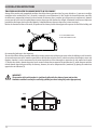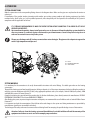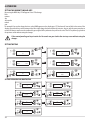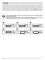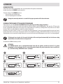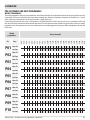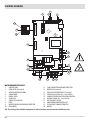
1
INSTALLATION GUIDE
INSERT
INSERTO
VIVO 80
PELLET
HYDRO
Translation of the original instructions
EN
TABLE OF CONTENTS
INTRODUCTION.............................................................................................................1
1-WARNINGS AND WARRANTY CONDITIONS......................................................................2
2-INSTALLATION INSTRUCTIONS......................................................................................5
3-INSTALLATION AND ASSEMBLY...................................................................................13
4-OPERATION..............................................................................................................25
5-SAFETY DEVICES AND ALARMS....................................................................................47
6-MAINTENANCE AND CLEANING...................................................................................51
7-PROBLEMS/CAUSES/SOLUTIONS.................................................................................56
8-WIRING DIAGRAMS...................................................................................................60
II
INTRODUZIONE
INTRODUCTION
Dear Customer,
Thank you for having chosen our product.
To allow for optimal operation and for you to enjoy the warmth and sense of wellbeing that the fire can convey in your
home, we advise you to read this manual carefully before starting up the product for the first time.
REVISIONS TO THE PUBLICATION
The content of this manual is strictly technical and property of MCZ Group Spa.
No part of this manual can be translated into another language and/or altered and/or reproduced, even partially, in another form, by
mechanical or electronic means, photocopied, recorded or similar, without prior written approval from MCZ Group Spa.
The company reserves the right to make changes to the product at any time without prior notice. The proprietary company reserves its
rights according to the law.
CARE OF THE MANUAL AND HOW TO CONSULT IT
•
•
•
•
•
Take care of this manual and keep it in an easily accessible place.
Should the manual be misplaced or ruined, request a copy from your retailer or directly from the authorised Technical Assistance
Department.
“Bold text” requires particular attention.
“Text in “italics” is used to draw your attention to other paragraphs in this manual or any additional explanation.
A “Note” provides the reader with additional information.
SYMBOLS USED IN THE MANUAL
ATTENTION:
carefully read and understand the relative message because failure to comply with what is written can
cause serious damage to the product and put the user’s safety at risk.
INFORMATION:
failure to comply with these provisions will compromise the use of the product.
OPERATING SEQUENCES:
sequence of buttons to be pressed to access the menus or make adjustments.
MANUAL
carefully read this manual or the relative instructions.
Technical Dept. - All rights reserved - Reproduction is prohibited
1
1-WARNINGS AND WARRANTY CONDITIONS
SAFETY PRECAUTIONS
•
•
•
•
•
•
•
•
•
•
•
•
•
•
•
•
•
•
•
•
•
•
•
•
•
2
Installation, electrical connection, functional verification and maintenance must only be performed by qualified or
authorised personnel.
Install the product in accordance with all the local and national laws and Standards applicable in the relative place,
region or country.
This product is not intended for use by persons (including children) with reduced physical, sensory or mental
capabilities, or lack of experience and knowledge, unless they are supervised or trained on how to use the product by
a person responsible for their safety.
Only use fuel recommended by the company. The product must not be used as an incinerator. It is strictly forbidden to use liquid fuel.
The instructions provided in this manual must always be complied with to ensure the product and any electronic appliances
connected to it are used correctly and accidents are prevented.
The user, or whoever is operating the product, must read and fully understand the contents of this installation and use guide before
performing any operation. Errors or incorrect settings can cause hazardous conditions and/or poor operation.
Do not use the product as a ladder or supporting structure.
Do not place laundry on the product to dry. Any clothes horses or similar objects must be kept at a safe distance from the product.
Fire hazard.
All liability for improper use of the product is entirely borne by the user and relieves the Manufacturer from any civil and criminal liability.
Any type of tampering or unauthorised replacement with non-original spare parts could be hazardous for the operator's safety and
relieve the company from any civil and criminal liability.
Most of the surfaces of the product are very hot (door, handle, glass, smoke outlet pipes, etc.). Avoid contact with these parts
unless adequate protective clothing is worn or appropriate means are used, such as heat protective gloves or cold
handle type operating systems.
It is forbidden to operate the product with the door open or the glass broken.
The product must be powered by a system that is equipped with an effective earth system.
Switch the product off in the event of a fault or malfunctioning.
Accumulated unburned pellets in the burner after each "failed start-up" must be removed before starting up again.
Do not wash the product with water. The water could get inside the unit and damage the electrical insulation and cause electric
shocks.
Do not stand in front of the product for a long time. Do not overheat the room where the product is installed. This could cause injuries
and health problems.
Do not put any fuel other than wood pellets in the hopper.
Install the product in rooms that are adequately protected against fire and equipped with all the utilities such as supplies (air and
electricity) and smoke outlets.
If a fire breaks out inside the chimney, switch the appliance off, disconnect it from the mains and do not open the door. Then contact
the competent authorities.
The product and the ceramic/serpentine cladding must be stored in a place where there is no humidity and must not be exposed to
the elements.
It is recommended not to remove the feet that support the product in order to guarantee adequate insulation, especially if the
flooring is made of flammable material.
If the ignition system is faulty, do not force ignition with flammable materials.
Special maintenance must only be performed by authorised and qualified personnel.
Assess the static conditions of the surface on which the weight of the product will rest and provide suitable insulation if it is made of
flammable material (e.g. wood, fitted carpet or plastic).
1-WARNINGS
AND
WARRANTY CONDITIONS
1-AVVERTENZE
E CONDIZIONI
DI GARANZIA
INFORMATION:
Please contact the retailer or qualified personnel authorised by the company to resolve a problem.
• only fuel stipulated by the company must be used.
• Check and clean the smoke outlet pipes regularly (connection with the product).
• The product is not a cooking appliance.
• Always keep the cover of the fuel hopper closed.
• Keep this instruction manual in a safe place as it must accompany the product throughout its working life. If it is sold or transferred
to another user, always make sure that the manual accompanies the product.
INTENDED USE
The product only works with wood pellets and must be installed indoors.
WARRANTY CONDITIONS
The company provides a product warranty, excluding the parts subject to normal wear stipulated below, for a period of two years
from the date of purchase, which is proven by a supporting document that contains the name of the seller and the date when the sale took
place. Warranty cover is valid if the completed warranty is returned within 8 days and the product is installed and tested by a qualified
installer, according to the detailed instructions provided in the instruction manual supplied with the product.
The term ‘warranty’ refers to the (free-of-charge) replacement or repairs of parts acknowledged to be faulty due to manufacturing
defects.
RESTRICTIONS
The above-mentioned warranty does not cover parts of electrical and electronic components and fans, which are covered
for 1 year from when the product is purchased, proof of which is provided as specified above. The warranty does not cover parts subject
to normal wear, such as: gaskets, glass and all parts that can be removed from the firebox.
Replaced parts will be covered by the warranty for the remaining period of the warranty in force as from the date of purchase of the
product.
EXCLUSIONS
Variations in colour of the painted or ceramic/serpentine parts and crazed ceramics do not constitute grounds for a claim as they are
natural characteristics of the material and product use.
The warranty does not cover any part that may be faulty as a result of negligence or careless use, incorrect maintenance or installation that
does not comply with the company's instructions (see the relative chapters in this user manual).
The company declines all liability for any damage which may be caused, directly or indirectly, to persons, animals or objects as
a consequence of non compliance with all the prescriptions specified in the manual, especially warnings regarding installation,
use and maintenance of the appliance.
If the product does not work correctly, contact your local retailer and/or importer.
Damage caused during transport and/or when handled is excluded from the warranty.
The supplied installation guide is the only reference for installation and product use.
The warranty will be rendered null and void in the event of damage caused by tampering, atmospheric agents, natural disasters, electrical
discharges, fire, defects in the electrical system, and maintenance not being performed at all or as indicated by the manufacturer.
Technical Dept. - All rights reserved - Reproduction is prohibited
3
1-WARNINGS AND WARRANTY CONDITIONS
INTERVENTION REQUEST
The company declines all liability if the product and any other accessory is used incorrectly or altered without
authorisation.
All parts must be replaced with original spare parts.
The request must be sent to the retailer who will forward it to the Technical Assistance Service.
SPARE PARTS
Only use original spare parts. The retailer or service centre can provide all the useful information regarding spare parts.
It is recommended not to wait for the parts to be worn before having them replaced. It is important to perform regular maintenance.
PRECAUTIONS FOR CORRECT DISPOSAL OF THE PRODUCT IN ACCORDANCE WITH THE EUROPEAN DIRECTIVE
2002/96/EC AND ITS SUBSEQUENT AMENDMENT 2003/108 EC.
At the end of its working life, the product must not be disposed of as urban waste.
It must be taken to a special differentiated waste collection centre set up by the local authorities or to a retailer that provides this service.
Disposing of the product separately prevents possible negative consequences for the environment and health deriving from inappropriate
disposal and allows to recycle its materials in order to obtain significant savings in energy and resources.
As a reminder of the need to dispose of appliances separately, the product is marked with a crossed-out wheeled dustbin.
4
2-INSTALLATION INSTRUCTIONS
The requirements in this chapter refer to the regulations of the Italian installation Standard UNI 10683. In any case, always comply with
the regulations in force in the country of installation
PELLETS
Wood pellets are manufactured by hot-extruding compressed sawdust which is produced during the processing of natural dried wood
(without paints). The compactness of the material is guaranteed by the lignin contained in the wood itself and allows pellets to be
produced without glue or binders.
The market offers different types of pellets with characteristics that vary according to the wood mixtures used. The diameter varies
between 6 and 8 mm, with a standard length ranging from 5 to 30 mm. Good quality pellets have a density that varies between 600 and
over 750 kg/m3, with a moisture content that ranges from 5% to 8% of its weight.
Pellets have technical advantages besides being an ecological fuel, as the wood residue is used completely, thereby achieving cleaner
combustion than that of fossil fuels.
Good-quality wood has a calorific value of 4.4 kW/kg (15% moisture, after about 18 months of seasoning), whereas that of pellets is 4.9
kW/kg. To ensure good combustion, the pellets must be stored in a dry place and protected from dirt. Pellets are usually supplied in 15 kg
bags, therefore, storing them is very convenient.
Good quality pellets guarantee good combustion, thereby decreasing harmful emissions into the atmosphere.
15 Kg BAGS OF FUEL
The poorer the quality of the fuel, the more often the internal parts of the brazier and combustion chamber must
be cleaned.
DINplus, Ö-Norm M7135 and Pellet gold are examples of the major quality certifications of pellets in the European market and
guarantee that the following are complied with:
•
•
•
•
•
•
•
calorific value: 4.9 kWh/kg.
Water content: max 10% of the weight.
Percentage of ash: max 0.5% of the weight.
Diameter: 5 – 6 mm.
Length: max 30 mm.
Content: 100% untreated wood with no added binding agents (max percentage of bark: 5%).
Packaging: in bags made from environmentally friendly or biologically decomposable material.
The company strongly recommends using certified fuel for its products (DINplus, Ö-Norm M7135 or Pellet Gold).
Poor quality pellets or others that do not comply with that specified previously compromises the operation of your
product and can therefore render the warranty and product liability null and void.
Technical Dept. - All rights reserved - Reproduction is prohibited
5
2-INSTALLATION INSTRUCTIONS
PRECAUTIONS REGARDING INSTALLATION
IMPORTANT!
Product installation and assembly must be carried out by qualified personnel.
The product must be installed in a suitable place for it to be regularly opened and routine maintenance to be performed.
The site must be:
• compliant for proper operation.
• Equipped with an adequate smoke expulsion system.
• Equipped with ventilation intake from outside.
• Equipped with 230V 50 Hz power supply with an EC compliant earth system.
The product must be connected to a chimney or an internal or external vertical duct that complies with the regulations in
force. The product must be positioned in such a way that the electrical socket is accessible.
IMPORTANT!
The product must be connected to a chimney or a vertical duct that can expel the smoke at the highest point of the
building.
In any case smoke derives from combustion of types of wood and if it comes in contact with or close to walls, these
can become dirty. Moreover, utmost attention is required as they are almost invisible but very hot and can cause
burns. The holes of the external air inlet and the smoke outlet pipe must be drilled before positioning the product.
THE OPERATING ENVIRONMENT
For correct operation and even distribution of heat, the product must be placed where the air required for combustion can flow.
The volume of the room should be no less than 15 m3.
Air must enter through permanent openings made in the walls (near the product) that reach outwards with a minimum section of 100 cm2
without the protective grille (in the case of a non-Oyster installation, i.e. without external ducted combustion air).
These openings (air inlets) must be made in such a way that it is impossible for them to be obstructed in any way.
Air can also be drawn from adjacent rooms to the one that is to be ventilated, provided they have an external air inlet and are not used as a
bedroom or bathroom or where there is a fire hazard, such as: garages, timber storerooms, warehouses of flammable materials, observing
under all circumstances the provisions of all the applicable standards in force.
If the product is placed too close to the wall it could cause overheating and damage the plaster (yellowing, cracking,
etc.).
6
2-INSTALLATION INSTRUCTIONS
POSITIONING AND RESTRICTIONS
In the case of simultaneous installation with other heating appliances, provide appropriate air inlets for each one (according to the
instructions of each product).
The product cannot be installed (except for sealed or closed operation appliances with external ducted combustion
air intake):
• in bedrooms or bathrooms;
• in rooms where there are liquid fuel appliances with continuous or intermittent operation that draw the
combustion air from the room they are installed in;
• in rooms where there are B-type gas heating appliances, with or without domestic hot water production and
interconnecting rooms;
• where another heating appliance is installed without an independent air flow.
It is forbidden to place the product in an explosive atmosphere.
MINIMUM DISTANCES
VIVO 80 PELLET HYDRO
Non-flammable walls
A
Flammable walls
B
Hydro Version
A = 50 mm
B = 50 mm
A = 100 mm
B = 100 mm
If particularly delicate objects are present, such as furniture, curtains or sofas the distance of the product must be significantly increased.
If the floor is made of wood, it is recommended to place a floor protection in accordance with the Standards in force
in the country of installation.
Heat-sensitive or flammable objects cannot be placed near the product. Keep such objects at a minimum distance of
80 cm from the outermost point of the product.
Technical Dept. - All rights reserved - Reproduction is prohibited
7
2-INSTALLATION INSTRUCTIONS
CONNECTION OF THE SMOKE EXHAUST DUCT
When making the hole for the passage of the smoke discharge pipe, one must take into account the possible presence of flammable
materials. If the hole must be made through a wooden wall or thermolabile material, the INSTALLER MUST first of all use the appropriate
wall fitting (minimum diameter 13 cm) and suitably insulate the pipe of the product that passes through it using adequate insulating
materials (1.3 - 5 cm thick with minimum thermal conductivity 0.07 W/m°K).
The same minimum distance must be applied if the pipe of the product must pass through vertical or horizontal sections near the
thermolabile wall.
It is recommended to use an insulated double-wall pipe in external sections in order to prevent condensation from forming.
The combustion chamber works in negative pressure.
SMOKE EXHAUST
COUPLING
8
2-INSTALLATION INSTRUCTIONS
Always use pipes and fittings with appropriate seals that guarantee tightness.
It must be possible to inspect all sections of the flue duct and they must be removable for periodic internal cleaning (T-fitting with
inspection hole).
Position the product considering all the above requirements and instructions.
IMPORTANT!
The following conditions must be complied with when connecting the appliance to the chimney:
• the smoke duct must be at least category T200 (or higher if required by the smoke temperature of the appliance)
and P1-type (airtight).
• All 90° angles (max. 3) in the smoke exhaust duct must be preferably fitted with the relative T-fittings with
inspection hole. (See pellet product accessories).
• It is strictly forbidden to fit a mesh at the end of the exhaust pipe as it could cause the product to malfunction
(due to clogging).
• It is forbidden to use counter-sloping pipes.
• The horizontal section of the smoke duct must not be longer than 2-3 m.
• It is also recommended not to exceed 6 metres in length with the pipe Ø 80 mm.
• The smoke duct must not cross rooms in which it is forbidden to install combustion appliances.
H > 4 mt.
2 - 3 mt. MAX
H > 1,5 mt.
3-5 %
Technical Dept. - All rights reserved - Reproduction is prohibited
9
2-INSTALLATION INSTRUCTIONS
CONNECTION TO THE EXTERNAL AIR INLET
It is essential for the room where the product is installed to be adequately ventilated in order to guarantee sufficient air for proper
combustion in the appliance. This is possible by means of suitable ventilation openings in the room itself or in an interconnected room
through a permanent opening between the rooms (room ventilation is excluded in the case of installation with Oyster technology, where
combustion air is ducted directly from outside)
For this purpose, drill a hole on the outer wall close to the product with a minimum section of 80 cm² (11 cm in diameter or 10x10 cm if
rectangular, considering the protective grilles), protected by a grille on the outside.
The air inlet must also:
• be protected with a grid, metal mesh, etc. without reducing the net section.
• Be positioned in such a way so as not to be obstructed.
• Allow maintenance to be performed.
• Be directly interconnected with the room where the product is installed.
• In the case of ducting, up to 3.5 linear metres, increase the cross-section by about 5%, whereas for longer ducts, increase it by 15%.
Remember that the ventilation grilles always show the useful section in cm2 on one side. When choosing the grille
and size of the hole, check that the useful section of the grille is larger or equal to the section required by the
company for product operation.
IMPORTANT!
The air flow can also be drawn from an adjacent room to that of the room where the product is installed, provided
the air can flow freely through permanent openings interconnected with the outside; air inlets connected to thermal
units, garages, kitchens or bathrooms must be avoided.
CONNECTION TO THE CHIMNEY
The chimney is the fundamental element for smoke expulsion and must therefore comply with the following requirements:
• be waterproof and thermally insulated.
• Be made of suitable materials that resist mechanical stress over time, heat, the effects of the combustion products and any possible
condensation.
• Have a vertical set-up with deviations from the axis of no more than 45° and free of bottlenecks.
• Must be suitable for the specific operating conditions of the product and have the CE marking (EN1856-1, EN1443).
• Must be adequately sized for the draught/smoke expulsion requirements that are necessary for the product to operate correctly
(EN13384-1).
• The internal section is preferably circular.
• In the case of a pre-existing product that has been used, it must be cleaned.
• The chimney must not be shared with other appliances.
The chimney is fundamental for correct operation and safety of your product.
Hereunder are a few guidelines for a correct installation. Any alternative configurations must be suitably sized in accordance with the
general method of calculation of UNI EN 13384-1.
10
2-INSTALLATION INSTRUCTIONS
CONNECTIONS
CONNECTION TO THE CHIMNEY
CONNECTION TO AN EXTERNAL DUCT
CONNECTION TO THE CHIMNEY
WITH AN INSULATED OR DOUBLE-WALL
PIPE
The chimney's internal dimensions must
not exceed 20x20 cm or 20 cm diameter;
in the event of bigger sizes or bad chimney
conditions (e.g. cracks, poor insulation,
etc.), it is advisable to fit a stainless steel
pipe of suitable diameter throughout the
length of the chimney right to the top.
The minimum internal dimensions of the
external duct must be 10x10 cm or 10 cm
in diameter and must not exceed 20x20 cm
or 20 cm in diameter.
Only stainless steel insulated (double-wall)
pipes must be used, which are smooth on
the inside and fixed to the wall. Flexible
stainless steel pipes must not be used.
,5 mt.0,5 mt.0,5 mt.
1
1
1 0,5 mt.0,5 mt.0,5 mt.
1
1
The connection between the product and
the chimney or the smoke duct must not
have an inclination that is less than 3% in
the horizontal sections, which must have
a maximum overall length of 2/3 m. The
vertical section between one T-fitting and
another (angle) must not be less than 1.5
m.
1
1
1
2
2
3
3
0,5 mt.
0,5 mt.0,5 mt.
2 - 3 mt.
2-3
MAX
mt.
2 - MAX
3 mt. MAX
1) WINDPROOF CHIMNEYPOT
•
•
•
•
•
2) CHIMNEY
3
2
3
2
3
2
3
3-5 %3-5 % 3-5 %
H > 1,5 mt.
3
2
H > 1,5 mt.
3
2
H > 1,5 mt.
2
3) INSPECTION HOLE
Use adequate instruments to verify that there is a minimum draught of 5 Pa.
Set-up an inspection hole at the bottom of the chimney to perform periodic checks and cleaning, which must
be done annually.
The connection to the chimney must be sealed and the fittings and pipes recommended by us must be used (CE
marked in accordance with EN1856-2 with the minimum requisites: T200 and P1).
You must ensure that a windproof chimneypot is installed in accordance with the regulations in force.
This type of connection guarantees smoke expulsion even in the event of a temporary power cut.
Technical Dept. - All rights reserved - Reproduction is prohibited
11
3
2-ISTRUZIONI PER
L'INSTALLAZIONE
2-INSTALLATION
INSTRUCTIONS
TING PROBLEMS RELATED TO DRAUGHT DEFECTS IN THE CHIMNEY
Among all the weather and geographical conditions that affect chimney operation (rain, fog, snow, altitude a.s.l., exposure to sunlight,
orientation to the cardinal points, etc.), the wind is certainly the most determinant. In fact, besides the thermal depression caused by
the difference in temperature between inside and outside the chimney, there is another type of depression (or overpressure): dynamic
pressure caused by the wind. An updraft always increases depression and therefore the draught. A horizontal wind increases depression
provided the chimneypot has been installed properly. A downdraft always decreases depression, at times inverting it.
Besides the direction and force of the wind, the position of the chimney and the chimneypot with respect to the roof of the building and
A
B
A=LESS FAVOURABLE POINTS
B=MOST FAVOURABLE POSITION
the surrounding landscape is also important.
The wind also affects chimney operation indirectly by creating overpressure and depression zones within the building as well as outside.
An internal overpressure can be created in rooms that are directly exposed to the wind (2), which can enhance the draught in stoves and
fireplaces, however, it can be counteracted by the external overpressure if the chimneypot is situated on the side exposed to the wind
(1). On the other hand, a dynamic depression can be created in rooms that are opposite the wind direction (3), which competes with the
natural thermal depression generated by the chimney, however, this can be compensated for (sometimes) by placing the smoke duct
opposite the wind direction (4).
IMPORTANT!
The operation of the pellet product is significantly affected by the chimney layout and position.
Hazardous conditions can only be resolved by qualified personnel setting the product appropriately.
WIND
1
4
2
12
3
3-INSTALLAZIONE
3-INSTALLATION
AND
E MONTAGGIO
ASSEMBLY
DRAWINGS AND CHARACTERISTICS
VIVO 80 PELLET HYDRO DIMENSIONS (dimensions in mm)
786.5
40
40
677
600
40
40
155
10
600
48
Ø2
09
0
Ø8
355
53.5
87.8
45
45
Technical Dept. - All rights reserved - Reproduction is prohibited
13
3-INSTALLATION AND ASSEMBLY
TECHNICAL CHARACTERISTICS
VIVO 80 PELLET HYDRO
Type of fuel
Pellets
Nominal output power:
16.9 kW / 14534 kcal / 14.2 kw H2O/12212 kcal
Global heat output Min:
4.9 kW / 4,214 kcal / 3.5 kw H2O/3,010 kcal
Efficiency at Max
90,1%
Efficiency at Min
95,2%
Temperature of exhaust smoke at Max
150°C
Temperature of exhaust smoke at Min
65°C
Particulate/OGC / Nox (13%O2)
20 mg/Nm3 - 1.1 mg/Nm3 - 117 mg/Nm3 (13% O2)
CO at 13% O2at Min and at Max
0,023 – 0,015%
CO2 at Min and at Max
6,4 - 9,8%
Recommended draught at Max power
0.12 mbar - 12 Pa
Recommended draught at Min power
0.06 mbar - 6 Pa
Maximum operating pressure
2.5 bar
Mass of smoke at Min and at Max
5.3 - 12.5 g/sec
Hopper capacity
20+15 litres
Type of pellet fuel
Pellet diameter 6-8 mm and size 5/30 mm
Pellet hourly consumption
Min ~ 1 kg/h* - Max ~ 3.6 kg/h*
Autonomy
At min ~ 27 h* - At max ~ 10 h*
Heatable volume m
363/40 – 415/35 – 484/30 **
Combustion air inlet
External diameter 50 mm
Smoke outlet
External diameter 80 mm
Electrical power consumption
Max 420 W - Med. 80 W
Supply voltage and frequency
230 Volt / 50 Hz
Net weight
160 kg
Weight with packaging
170 kg
3
* Data that may vary depending on the type of pellets used.
** ** Heatable volume based on the heat demand of cal/m3 40-35-30 (respectively 40-35-30 Kcal/h per m3).
Tested according to EN 14785 in accordance with Directive 89/106/EEC (Construction Products).
14
3-INSTALLATION AND ASSEMBLY
PREPARATION AND UNPACKING
The product is supplied in a single package. Inside the package there are the tube, the loading door, the frame and ventilation grilles.
Open the package, remove the product from the pallet and set it in the pre-selected place, making sure this complies with the requirements.
PRODUCT PACKAGING
The two brackets must be removed in order to remove the product from pallet, by loosening the two flanged nuts and the two screws.
The appliance must always remain in a vertical position and handled solely with a cart. Pay particular attention to the door and its glass,
protecting them from mechanical knocks that would compromise their integrity.
SCREW
NUT
NUT
BRACKET
SCREW
Always handle the product with care. If possible, unpack the product near the place of installation. The materials that make up the
packaging are neither toxic nor harmful, and so require no particular disposal measures. Therefore, the end user is responsible for product
storage, disposal or possible recycling in compliance with the relative applicable laws.
If the product must be connected to an exhaust pipe that goes through the rear wall (to enter the flue), make sure not to force it in.
Technical Dept. - All rights reserved - Reproduction is prohibited
15
3-INSTALLATION AND ASSEMBLY
POSITIONING
Before installing the product assess the optimal position.
One can install the product in a pre-existing traditional fireplace or as a new system.
In addition to lift the product to the recommended height of 600 mm one can purchase a metal support separately (refer to the relative
optional accessories price list)
INSTALLATION IN A PRE-EXISTING FIREPLACE
Assess the following elements:
The supporting surface of the product must have the following characteristics:
• support the weight of the product and of any accessories
• consistency such as to allow anchoring by means of plugs for safety
• perfectly level
• the jambs as perpendicular as possible to the surface
The housing compartment must be large enough to accommodate the product.
After verifying the conditions needed for proper installation proceed with the installation of the product:
• fix the base of the product to the supporting surface
• carry out all chimney plumbing and electrical connections in compliance with the regulations in force.
Any space between the cladding walls and the product can be closed via a compensation frame that can be easily disassembled in the
event of maintenance of the insert.
It is mandatory to fix the product to the supporting surface, as otherwise the product could tilt when extracted.
One must check that all connections (plumbing and electrical) enable to extract the product.
INSTALLATION AS A NEW SYSTEM
Assess the following elements:
The supporting surface of the product must have the following characteristics:
• support the weight of the product and of any accessories
• consistency such as to allow anchoring by means of plugs for safety
• perfectly level
After verifying the conditions needed for proper installation proceed with the installation of the product:
• fix the base of the product to the supporting surface
• carry out all chimney plumbing and electrical connections in compliance with the regulations in force.
It is mandatory to fix the product to the supporting surface, as otherwise the product could tilt when extracted.
One must check that all connections (plumbing and electrical) enable to extract the product.
• Proceed to assemble the cladding.
It is best to leave the product without cladding for a few days to check the tightness of all plumbing connections.
For any type of installation, both on a new system as on an existing one, it must be possible to inspect the connections
of the hoses fitted on the wall, because when the product is extracted one must disconnect the pipes from the system.
16
3-INSTALLATION AND ASSEMBLY
FASTENING TO THE BASE OF THE INSERT
It is mandatory to anchor the product to a support as the authorised technician can remove the combustion chamber from its seat by
means of two extendable guides while performing the annual maintenance.
Fasten the insert as follows:
• measure the distance (A) from the edge of the frame to the outer edge of the support for it to be adequately set back into place.
A=590 mm (measurement from the edge of the frame to the outer edge of the support).
A1= 3 mm (measurement from the outer edge of the wall to the edge of the frame).
• Remove compensation frame C (see the relative paragraph).
• Loosen the lower screws (B) under the frame.
• Then remove the machine and separate it from its support (D).
• Set the support (D) away from the wall at the previously measured distance.
• Fasten the support (D) to the base (E) or to the optional support with the screws supplied, making sure that the support anchor
surface (D) and the wall are perpendicular.
• Set the machine back on the support (D), insert the screws (B) again, making sure the machine and the support are well secured in
order to guarantee product operation.
A1=3 mm
A=590 mm
It is very important to make sure the positioning measurements of the product base have been respected and the support
anchor surface and the wall are perpendicular. Also make sure that the screws secure the machine to the support.
The product can be installed at the desired height by constructing a suitable platform. This support must be made of non-flammable
material.
The company declines all liability for any damage to objects and persons if the above-mentioned precautions are not
complied with.
Technical Dept. - All rights reserved - Reproduction is prohibited
17
3-INSTALLATION AND ASSEMBLY
PELLET LOADING CHUTE ASSEMBLY
Another decision to be made before positioning the product is to define the side on which to install the chute for loading fuel. The pellets fuelled Vivo 80 Hydro is delivered with two clamps, the connection pipe and chute with hatch.
The chute can be fitted on the right side, on the left side or frontally. The connection pipe is 1 metre long.
It is mandatory to shorten the connection pipe, depending on its positioning (side or front), so that it is well taut and
forms a minimum angle with respect to the horizontal as shown in the drawing. This operation is necessary for the pellets'
descent.
Before setting up the cladding carry out a fuel loading test to assess its proper descent towards the hopper.
It is mandatory to insulate the pipe properly in the event this is fitted on the left side in correspondence of the smoke evacuation duct. Fire hazard!
Chute assembly
In the event one decides to position the pipe laterally, the distance from the machine axis to the wall must be at least 80 cm (figure
shown here).
To position the chute act as follows:
• Connect the supplied pipe to the product paying attention that it is rotated sideways, and fasten it with the clamp.
• Connect the pipe (in the upper part) to the opening of the door structure with the supplied clamp.
• Position the pipe with the door structure so that, when the cladding is complete, one can screw and fasten it to the cladding wall in
correspondence of the hole made for its insertion.
• To assemble the external door, which must only be done when the cladding is complete, refer to the relative section.
800 max
18
800 max
3-INSTALLATION AND ASSEMBLY
HOOD VENTILATION GRILLES
Foreword
Depending on how the product is positioned, one must provide grilles for ventilation.
If inserted in existing cladding, the ventilation grilles on the cladding will be used.
If used as a new installation, the company recommends installing the ventilation grilles as described in the following paragraph.
CONVECTION HOT AIR
HOT AIR INFLOW FROM THE ROOM
HOOD VENTILATION GRILLES FOR NEW CLADDING
It is mandatory to install the hood ventilation grilles of the manufacturer or grilles that can guarantee the same functions
and the same air passage section.
The company cannot be held liable for any damage caused to the structure or the electrical components if this precaution
is not complied with.
The structure becomes very hot and it is essential that constant and efficient ventilation is always guaranteed inside the cladding.
This allows to recover part of the structure heat that would otherwise be lost if left inside the cladding, whilst guaranteeing perfect
product operation.
The company supplies the “Blade” nozzle that is to be installed in the upper part of the insert as shown in the figure.
CONVECTION HOT AIR: ONE MUST RELEASE THE
HOT AIR ACCUMULATED INSIDE THE CLADDING.
SUPPLIED “BLADE” GRILLE
AIR INFLOW FROM THE ROOM: ALLOWS AIR
RECYCLE. ONE MUST PROVIDE AN OPENING IN
THE LOWER PART OF THE CLADDING TO PROMOTE
CONVECTION.
Technical Dept. - All rights reserved - Reproduction is prohibited
19
3-INSTALLATION AND ASSEMBLY
ELECTRICAL CONNECTION
First connect the power cable to the rear part of the product and then to a wall socket, which must always be accessible.
Should this not be possible, during installation, insert appropriate power supply disconnection devices, in compliance with the national
regulations regarding electrical installations.
It is recommended to disconnect the power cable when the product is not used.
SETTING UP THE CLADDING
The product must be fully tested before the cladding is applied. The company cannot be held liable for any damage to the
cladding should operating anomalies arise, which were not verified before the cladding was applied to the product.
IT IS MANDATORY to check the tightness of all the pipes through which smoke passes (smoke fitting, gaskets and flue coupling)
before setting up the cladding.
READ THE "OPERATION TEST" CHAPTER BEFORE STARTING ANY PRODUCT CLADDING OPERATION.
The product and the cladding parts must be fastened together WITHOUT COMING INTO CONTACT WITH THE STEEL STRUCTURE in
order to prevent heat from being transmitted to the marble and/or stone and to allow for normal thermal expansion. Pay attention to the
wood finishes, such as beams or shelves.
It is recommended to set up the counter hood made of 15 to 20 mm thick fireproof plasterboard with a freestanding frame made of a
galvanised profile to prevent bearing the weight on the cladding components (wooden beams or marble lintels), which do not have a
freestanding structure and in order to intervene easily in case of anomalies and/or future maintenance. Dry mount the hearth
of the cladding, leaving a 1 cm gap between the insert and the hearth for insulation.
20
3-INSTALLATION AND ASSEMBLY
WOODEN BEAM INSULATION
If you wish to mount a wooden beam, it must be protected with adequate insulation from the hot parts in order to prevent the risk of fire
or damage to the cladding.
1 - INSULATION APPLIED OR TO BE APPLIED
2 - WOODEN BEAM
3 - MARBLE OR OTHER MATERIAL
STANDARD CLADDING ASSEMBLY
The installation guide found in each specific cladding must be referred to for the assembly of MCZ product specific claddings.
FRAME ASSEMBLY
Once the cladding and/or the plasterboard wall is set up, fit the frame.
This frame is meant for finishing and covering the gap between the metal structure of the product and the cladding.
The four screws for fixing the frame are already screwed to the lateral columns. Simply open the door of the product, insert the frame as
shown in the figure, loosen the screws fixed to the columns and tighten them fastening the frame to the structure.
LATERAL COLUMNS
FRAME
SCREWS
Technical Dept. - All rights reserved - Reproduction is prohibited
21
3-INSTALLATION AND ASSEMBLY
DIAGRAM FOR MAKING HOLES IN THE CLADDING
PELLET LOADING DOOR INSERTION HOLE
The product can be installed on a brick base built on site or one can purchase the support (optional) that enables to raise the product to
a suitable height. The recommended measurements go from 50 to 60 cm below the product support surface.
To make the hole for inserting the loading door there are standard measures required by the same length of the loading pipe.
Below is the drawing with the recommended and required measurements in order to ease fast installation.
22
3-INSTALLATION AND ASSEMBLY
PRODUCT INLET HOLE
610
The hole to be made in the wall must be 765*610 mm. These measurements allow the frame to cover the gap that remains between the
product and the hole and also allow the product to be removed if maintenance is to be performed and/or parts are to be replaced.
765
SWITCH AND CONTROL PANEL CONNECTION
The emergency panel and switch are already fitted on the pellets loading door and are already connected to the relative cables by the
manufacturer. Take the switch cable and connect it to the socket on the rear of the product.
The control panel must instead be connected to the circuit board in position 1.
•
•
•
•
•
•
Pay utmost attention when handling panels connected to the relative cables.
Cables must stay in areas away from heat or in areas where they cannot be damaged in the event of extracting
the product.
For proper operation make the flat cable and the switch cable pass far from each other, with different paths.
Do not force insertion of the connector under any circumstances.
Do not fold and/or twist the cables.
Do not modify the connectors or cabling or panel supports.
DOOR ASSEMBLY
Once the electrical cabling is complete, before fixing the hood door permanently, carry out an operation test.
If the test has a positive outcome, fix the door to the hood with four screws, using the four holes present on the door frame and indicated with the letter (B).
The holes indicated on the horizontal profiles of the door (A) are instead for fixing the door frame to the chute frame to permanently
fasten the two elements, enclosing the hood wall in the middle.
One must preventively make a rectangular hole in the hood at a height determined by how the optional support has been installed or by
how the brickwork platform has been constructed.
Technical Dept. - All rights reserved - Reproduction is prohibited
23
3-INSTALLATION AND ASSEMBLY
A
B
B
B
B
A
PELLETS DOOR OPENING/CLOSING
A
The door is fitted with a pressure closure and is therefore completely free of handles or grips.
To open or close the door, press the upper left corner. With a simple press this will hook on or unhook from the closure latch placed on
the door frame.
24
4-OPERATION
BEFORE START-UP
GENERAL PRECAUTIONS
Remove all components that could burn from the firebox and glass (instructions, various adhesive labels and any polystyrene).
Check that the brazier is positioned correctly and rests properly on the base.
After a long period of inactivity, remove any pellets left in the hopper (using a vacuum cleaner with a long pipe ), as they
could have absorbed moisture, thereby altering their original characteristics and no longer being suitable for combustion.
The first start-up may not be successful as the feed screw is empty and does not always manage to load the required
amount of pellets in the brazier in time for the fire to be regularly ignited.
If a flame does not ignite after a number of failed start-ups, even though the pellet supply is correct, make sure the brazier is set in place
correctly, which must be interlocked in its seat and free from any ash deposits. If no anomaly is found during this inspection, there
may be a problem with the product components or installation may not be correct.
REMOVE THE PELLETS FROM THE BRAZIER AND CONTACT AN AUTHORISED TECHNICIAN.
Avoid touching the product during the initial start-up, as the paint hardens during this phase. If you touch the paint,
you may expose the steel surface.
If necessary, touch up the paint with the spray can of the specific colour.
It is good practice to guarantee effective ventilation in the room during the initial start-up, as the product will emit
some smoke and smell of paint.
Do not stand close to the product and air the room. The smoke and smell of paint will disappear after about an hour of operation, however,
remember they are not harmful in any case.
The product will be subject to expansion and contraction during the start-up and cooling phases, therefore light creaking noises may be
heard.
This is absolutely normal as the structure is made of laminated steel and must not be considered a defect.
Technical Dept. - All rights reserved - Reproduction is prohibited
25
4-OPERATION
It is extremely important to make sure the product is not immediately overheated and the temperature is increased gradually, initially
using low power.
This will prevent damaging the welds and the steel structure.
DO NOT EXPECT HEATING EFFICIENCY IMMEDIATELY!!!
LOADING THE PELLETS
Fuel loading is achieved via the lateral or frontal door to be fitted on the cladding, which enables access to the fuel loading chute.
The loading procedure is facilitated if performed in several steps as described below:
• open the door and pour half the contents directly from the sack or using the supplied scoop (A) onto the chute.
• Wait for the pellets accumulated on the chute to enter the hopper.
• Complete the operation by pouring the second half of the sack with the same procedure.
No other type of fuel other then pellets, in compliance with above-mentioned specifications, is to be inserted into
the hopper.
SCOOP A
Pellet
26
4-OPERATION
PLUMBING CONNECTION
IMPORTANT!
The connection of the stove to the plumbing system must be carried out ONLY by specialised personnel capable of
carrying out state of the art installation, in compliance with the standards in force in the country of installation.
The company will not be held responsible for damage to persons or things in the event of failed operation if the
aforementioned warning is not complied with
CONNECTION DIAGRAM
A = BOILER DELIVERY
B = BOILER DISCHARGE
C = BOILER RETURN
D = VENT
E = KLIXON 95°C OVERLOAD PROTECTOR
F = H2O TEMPERATURE PROBE
G = KLIXON 110°C OVERLOAD PROTECTOR
H = 3 BAR 1/2” SAFETY VALVE
B
A
C
A = 3/4”M BOILER DELIVERY
B = 1/2”M BOILER DISCHARGE
C = 3/4”M BOILER RETURN
Technical Dept. - All rights reserved - Reproduction is prohibited
27
4-OPERATION
SYSTEM CONNECTIONS
Make the connections to the corresponding fittings shown in the diagram above. Make sure the pipes are not placed under tension or
undersized.
If installation of the product involves interaction with another, pre-existing system complete with heating equipment (gas boiler,
methane boiler, diesel boiler, etc.), call in qualified personnel, who subsequently will be responsible for conformity of the system in
compliance with the applicable law in force.
IT IS STRONGLY RECOMMENDED TO WASH THE ENTIRE SYSTEM BEFORE CONNECTING IT IN ORDER TO GET RID OF
RESIDUES AND DEPOSITS.
Upstream from the product, always install gate valves so as to disconnect it from the plumbing system should it be
necessary to move it, or when it requires routine and/or special maintenance. Connect the product using hoses in
order not to constrain it excessively to the system.
The pressure discharge valve (B) is always connected to a water drain pipe. The pipe must be adequate to support the
water's high temperature and pressure.
A1 = HOSES
A2 = BOILER DISCHARGE TAP
A3 = SAFETY VALVE
SYSTEM WASHING
It is mandatory for the connections to be easily disconnectable via unions with swivel fittings. Fit suitable gate valves on the heating
system pipes.
To protect the heating system from harmful corrosion, fouling or deposits, it is of the utmost importance, before installing the product, to
wash the system in compliance with UNI-CTI 8065, using appropriate products such as, for example, Sentinel X300 (new systems), X400
and X800 (old systems) or Fernox Cleaner F3.
Complete instructions are provided with the products but, for further clarifications, please directly contact the manufacturer SENTINEL
PERFORMANCE SOLUTIONS LTD or Fernox COOKSON ELECTRONICS.
After flushing the system, to protect it against corrosion and deposits, we recommend the use of inhibitors such as Sentinel X100 or Fernox
Protector F1.
It is important to check the concentration of the inhibitor after each change to the system and during maintenance as prescribed by
manufacturers (specific tests are available at dealers).
The discharge of the safety valve must be connected to a collecting funnel for conveying the possible dredges in case of intervention.
Attention: failure to clean the heating system and the addition of a suitable inhibitor will void the warranty of the
equipment and other accessories such as for example pumps and valves.
28
4-OPERATION
SYSTEM FILLING
To load the heating system use the predisposed loading tap in the main boiler. During this operation, any air in the system is released via
the air valve located in the upper part of the product.
To allow the valve to release air it is recommended to loosen the screw on the valve itself (see figure). The filling pressure of the system
WHEN COLD must be 1 bar. If during operation the system pressure drops (due to evaporation of gases dissolved in the water) to values
lower than the minimum ones indicated above, the user must use the filling tap to bring the pressure back up to its initial pressure.
For proper operation of the stove WHEN HOT, the pressure in the boiler must be 1.5 bar.
Upon completion of this filling operation, always close the tap.
MANUAL AIR VALVE.
Attention: do not mix the heating water with antifreeze or corrosion substances in the wrong concentrations. It can
damage the seals and cause the onset of noise during operation.
Technical Dept. - All rights reserved - Reproduction is prohibited
29
4-OPERATION
WATER CHARACTERISTICS
The characteristics of the water used to fill the system are very important to prevent the build-up of mineral salts and the formation of
incrustations along the pipes, in the boiler and in the heat exchangers.
Therefore, please ASK YOUR PLUMBER FOR HIS ADVICE CONCERNING:
• Hardness of water circulating in the system, to prevent problems of incrustation and limescale, especially in the
domestic water heat exchanger. (> 25° French).
• Installation of a water softener (if water hardness exceeds 25° French).
• Filling the system with treated water (demineralised).
• Possibly providing an anti-condensation circuit.
• Installation of hydraulic shock absorbers to prevent water hammering along the fittings and pipes.
If you have very extensive systems (with a large amount of water) or which require frequent refilling, the installation of water softening
systems.
It should be remembered that incrustations drastically reduce performance due to their extremely low thermal
conductivity.
EXAMPLE INSTALLATION DIAGRAMS
The following diagrams are to be used only as a guideline. For proper connection, always follow the notes for the
plumbing and heating installer. The plumbing system must meet local, regional or national requirements in force.
Installation and verification of operation are to be performed only by specialised and authorized personnel. The
manufacturer will not be held liable for non-compliance with the provisions listed above.
KEY
M
Pressure gauge
BA
Storage boiler
V
Valve
RA
Radiators
A
Water hammer shock absorber
PR
Radiant panels
Flt
System filter
PS
Solar panels
RP
Pressure reduction valve
R
Tap
Add
Softener
C
Methane gas boiler
B
Boiler
30
4-OPERATION
INSTALLATION DIAGRAM FOR HEATING WITHOUT DOMESTIC WATER KIT
Technical Dept. - All rights reserved - Reproduction is prohibited
PRESSURE SAFETY DISCHARGE
SYSTEM RETURN
V
SYSTEM DELIVERY
M
V
RA
RA
RA
RA
This diagram is purely a guideline and therefore has no project value.
31
4-OPERATION
INSTALLATION DIAGRAM FOR HEATING COMBINED WITH A BOILER
RA
COLD DOMESTIC
WATER INLET
SYSTEM RETURN
SYSTEM DELIVERY
PRESSURE SAFETY DISCHARGE
V
M
V
B
RA
RA
A
R
HOT DOMESTIC WATER OUTLET
Add
RA
Flt
RP
This diagram is purely a guideline and therefore has no project value
32
4-OPERATION
INSTALLATION DIAGRAM COMBINED WITH A STORAGE TANK
A
R
Technical Dept. - All rights reserved - Reproduction is prohibited
PRESSURE SAFETY DISCHARGE
SYSTEM DELIVERY
M
V
V
SYSTEM RETURN
PS
BA
C
HOT DOMESTIC
WATER OUTLET
Add
RA
Flt
RA
RP
RA
COLD DOMESTIC
WATER INLET
FREDDA
PR
RA
PR
This diagram is purely a guideline and therefore has no project value.
33
4-OPERATION
It is good practice to guarantee effective ventilation in the room during the initial start-up, as the product will emit
some smoke and smell of paint.
Do not stand close to the product and air the room. The smoke and smell of paint will disappear after about an hour of operation, however,
remember they are not harmful in any case.
The stove will be subject to expansion and contraction during the start-up and cooling phases, therefore light creaking noises may be
heard.
This is absolutely normal as the structure is made of laminated steel and must not be considered a defect.
Make sure the plumbing system is sealed perfectly and that there are no leaks or pressure drops.
Make sure that all cut-off valves between the product and the system are open.
Make sure you have bled all air out of the system before start-up.
Make sure that internal devices work properly (flow switches, thermostats, etc.). Make sure that the combustion chamber and the chimney
are clean, and that the plumbing circuit is free of obstructions.
The basic settings ensure proper operation and prevent overheating during the first ignitions.
SETTINGS TO BE CARRIED OUT BEFORE THE INITIAL START-UP
SWITCHING ON/OFF
Once the power cable is connected in the rear part of the product, bring the switch, which is in the pellets loading door, to position (I). The
illuminated pushbutton switch will turn on.
The product remains switched off and the panel shows a first screen displaying OFF, by pressing any button a screen displaying MENU will
appear.
I/O SWITCH
CONNECT THE POWER
CABLE
The product is switched on and off by pressing key B on the control panel for 2 seconds.
After a start-up phase that lasts approximately 15 minutes, the product starts to work in steady-state conditions.
After switching off the product by pressing key B on the control panel, the cooling stage begins, which involves interruption of fuel
loading, brazier cleaning and ventilation until the product is sufficiently cool.
FEED SCREW LOADING
This function can only be activated when the product is off and allows the pellets to be loaded into the loading system (feed screw). It
can be used each time it runs out of pellets in the hopper (see alarm A02). It is useful to prevent failed start-ups (alarm A01) due to the
hopper being empty.
To activate the FEED SCREW LOADING function, with the product switched off, from the control panel enter the SETTINGS entry, select
FEED SCREW LOADING and ON. When the pellets start falling into the brazier deactivate FEED SCREW LOADING and switch on the product
34
4-OPERATION
CONTROL PANEL LOGIC
Some useful information is provided below to understand the logic and use of the control panel:
• The control panel backlight switches off after about 30" seconds of keypad inactivity. To switch the backlight on again simply press
any of the panel buttons.
• The first screen that appears displays the product operating status (ON, OFF, START-UP, SHUTDOWN..) which alternates according to
any activated settings (CHRONO, SLEEP, AUTO ECO..)
• By pressing any of the 4 keys around the display (C D E F) one enters the product operation setting screen (flame and ventilation
level, set temperature, automatic mode..). From this level the 4 keys around the display take on "dedicated" functions i.e. they are
directly referred to the corresponding wording that appears in the 4 corners of the display (e.g.: the wording at the top on the right
refers to key D).
• When modifying a setting on any menu level and the change is not confirmed via the "OK" key, leaving the keypad inactive for a few
seconds, the initial screen reappears automatically and the changes are not saved.
• If from any menu level one briefly presses the on/off key (B), the display automatically goes back to the initial screen (product
operation status) without saving any unconfirmed changes with the "OK" key.
•
KEY
A.
Display that indicates a variety of product information besides the identification code of any malfunction.
B.
ON/OFF key or ESC (exit from menu).
C.
Programme choice key (following screen).
D.
Programme choice key (following screen).
E.
Programme choice key (following screen).
F.
Programme choice key (following screen).
G
Receiver for remote control (if present)
IMPORTANT NOTE
It is possible to set the language on the control panel.
Technical Dept. - All rights reserved - Reproduction is prohibited
35
4-OPERATION
SETTING THE CURRENT TIME AND DATE
By pressing the MENU key SET will appear. Enter SET to change:
hour
minutes
day
day number
month
year
For example if we need to change the time, when HOUR appears on the display press SET, the hour will start to flash in the centre of the
display, then with the keys at the bottom on the left or right change the hour and then the minutes, day, etc. with the same procedure as
needed. All changes made must be confirmed by pressing the OK key otherwise they will not be saved. The ESC key allows tp go back to
the previous screen without saving the changes.
If the control panel keypad stays inactive for 10 seconds one goes back to the start-up screen without saving the
changes.
SETTING THE TIME
21.0°C
21.0°C
21.04
21.04
21.0°C
21.0°C
Mode:
AUTO
Mode:AUTO
Menu
Menu
Fan:A
Fan: A
Esc
Esc
OFF
OFF
Temp:22°C
Temp:
22°C
Esc
Esc
--
01
01
Hour
Ora
OFF
OFF
<<
OkOk
++
Esc
Esc
--
Data
DateeandOra
Time
SetSet
>>
01
01
Minuti
Minutes
OkOk
++
SETTING THE DAY/DAY NO./MONTH/YEAR
21.0°C
21.0°C
OFF
OFF
Esc
Esc
Mode:
AUTO
Mode:AUTO
Temp:22°C
Temp:
22°C
Menu
Menu
Fan:A
Fan: A
Set
Set
>>
Esc
Esc
Monday
Lunedi
Giorno
Day
Ok
Ok
++
Esc
01
Ok
Esc
01
Ok
+
DayNumber Numero +
-- Giorno
Esc
Esc
--
01
01
Mese
Month
Ok
Ok
++
<<
Esc
Esc
--
36
21.04
21.04
Data
Ora
Date andeTime
2012
2008
Anno
Year
Ok
Ok
++
--
21.04
21.04
4-OPERATION
SETTING THE LANGUAGE
Press the MENU key then scroll with the keys at the bottom on the right or left until SETTINGS appears, press SET and LANGUAGE will
appear, press SET again and set the chosen language.
By convention the days of the week are indicated with abbreviations deriving from the language set on the panel. In the case of English:
MO
MondayTH
ThursdaySU
Sunday
TU
TuesdayFR
Friday
WE
WednesdaySA
Saturday
21.0°C
21.0°C
OFF
OFF
Esc
Esc
<<
Impostazione
Setting
Esc
Esc
<<
21.04
21.04
Lingua
Language
Mode:
AUTO
Mode:AUTO
Temp:22°C
Temp:
22°C
SetSet
>>
Esc
Esc
SetSet
>>
Esc
Esc
<
<
<
<
Menu
Menu
Fan:A
Fan: A
Impostazione
Setting
SetSet
>>
ON
Lingua
Language
OK Set
> >
RECIPE SELECTION PROCEDURE
On the control panel menu, "Recipe" appears under the settings menu. This function is for increasing or decreasing pellets loading into
the hopper and is represented as follows:
• To increase: +1 +2 +3 that corresponds to 10-20-30% more compared to the standard recipe set by the company.
• To decrease: -1 -2 -3 that corresponds to 10-20-30% less compared to the standard recipe set by the company.
CHIMNEY SWEEP FUNCTION
ATTENTION.
The "Chimney sweep" function is a technical function aimed at a specialised technician for product calibration
(where required by law) therefore the user must absolutely not activate it.
To activate the Chimney Sweep function one must enter in MENU-SETTINGS-CHIMNEY SWEEP (after the °C-°F entry).
Once the function has been activated the stove will work at maximum power (loading, smoke ventilation, room ventilation) without
listening to any modulation/shutdown requests of the external (thermostat, eco-stop, modem, home automation control) and internal
probes. The only limit that must stay active is the safety threshold of 85°C in the boiler, and relative electronic shutdown in the event of
exceeding this parameter.
The test will work until the technician decides to disable the function by pressing esc or the on/off button.
SETTING WATER TEMPERATURE IN BOILER
The stove has already got a series of standard parameter settings which allow it to operate properly (water temperature 65°C). The water
temperature is shown on the control panel display.
If the user wishes to change the parameters relating to the temperature he/she can do so as follows:
T H2O = Maximum temperature of water in boiler. Upon reaching this temperature, the stove will reduce its performance to prevent
overheating.
Technical Dept. - All rights reserved - Reproduction is prohibited
37
4-OPERATION
The default temperature is 65°C and it can not be set below 50°C or above 80°C.
To adjust it: press any button; press the "menu" button, via the scrolling buttons display the “SET TEMP.H2O” screen; press the “SET” button;
set the desired temperature via the “<>” scrolling buttons; confirm the temperature with the “OK” button.
MANDATORY EXTERNAL ROOM THERMOSTAT (3) OR STORAGE TANK CONNECTION
One must connect the stove to an external thermostat "3" or to a storage tank; in addition one can connect to a home automation control
unit "4". If one wishes to connect the modem one must use clamp "2".
For the connection one must connect the cables to the product board in the positions indicated below.
It is not necessary to activate the room thermostat or storage tank on the control panel as it is set as active by default.
One recommends the installation to be carried out by a specialised technician.
2
1
3
4
5
1
COMPUTER CONNECTION (to be carried out by a specialised technician)
2
MODEM CONNECTION
3
EXTERNAL ROOM THERMOSTAT CONTROL UNIT CONNECTION
4
HOME AUTOMATION CONTROL UNIT CONNECTION
5
WIRELESS PROGRAMMABLE THERMOSTAT (OPTIONAL)
38
4-OPERATION
AUTOMATIC MODE WITH AUTO-ECO
This mode changes the behaviour of the product in automatic mode: upon reaching the temperature set by the user, the product
modulates at power 1 for a short period of time and then, if the temperature remains constant and higher than that set, it switches off.
The appliance switches back on automatically only when the room/water require heat again (not before an interval necessary for the
product to cool down). This option is recommended only if the product operates in rooms where heat dissipation is minimum over time.
ACTIVATION /DEACTIVATION OF AUTO-ECO MODE
This mode optimises product consumption in the event the product operates in well insulated rooms.
AUTO-ECO appears on the control panel display when this option is activated.
Press any button on the first screen with OFF and MENU will appear on the screen. Use the button at the bottom on the right to scroll
until SETTINGS appears, press the button at the top on the left relative to SET, scroll once again with the button at the bottom on the right
until AUTO-ECO appears. Select SET again at the top on the right and set OFF or ON with the button at the bottom on the right or left and
press OK to save the setting. When you return to the main menu you will note that the Mode setting is ECO, then press the bottom left or
right buttons to set the respective temperature and speed of the fans for the hot air expulsion. Follow the same procedure to disable the
AUTO-ECO function.
Example of AUTO-ECO mode operation
If the room temperature detected by the probe and shown on the control panel is 15°C and the temperature is set at 20°C, the product will
switch to the 5th power (according to a preset ramp-up) and once it has reached a temperature of 20°C, the stove will modulate and then
automatically switch off temporarily (STANDBY). When room temperature drops below the set value on the control panel (e.g. 18°C), and
sufficient switch-off time has elapsed, the product will automatically restart and run until 20°C are reached again. If the temperature read
by the room probe continues to exceed that set on the thermostat (e.g. 20-21°C), the stove will remain switched off.
In this mode, the user can switch the stove on by resetting the thermostat to a temperature that is higher than that in the room, or by
switching the appliance off by pressing button B for a few seconds and then switching it back on by pressing the same button.
There is no need to reset the AUTO-ECO mode as this is saved from when last used.
SLEEP FUNCTION
This function can only be displayed with the product switched on, and its purpose is to make the selection of a programmed shutdown
faster, without needing to programme the internal CHRONO-TIMER of the product.
21.0°C
21.0°C
OFF
OFF
Mode:
AUTO
Mode:AUTO
Temp:22°C
Temp:
22°C
Esc
Esc
21.04
21.04
Esc
Esc
<
<
Menu
Menu
Fan:A
Fan: A
ON
ON
Auto-Eco
Auto-Eco
21.0°C
21.0°C
OFF
OFF
OKOk
>>
21.04
21.04
SetSet
>>
Mode:
ECO
Mode:ECO
Menu
Menu
Fan:1
Fan: 1
Esc
Esc
SetSet
<
>>
Setting
< Impostazione
Mode:
ECO
Mode:ECO
Menu
Menu
Fan:1
Fan: 1
<
<
Esc
Esc
<<
Date and
Time
Data
e ora
Auto-Eco
Auto-Eco
Temp:22°C
Temp:
22°C
Temp:22°C
Temp:
22°C
SetSet
>>
Technical Dept. - All rights reserved - Reproduction is prohibited
39
4-OPERATION
To explain SLEEP function simply, one can say that it allows to switch off the product starting from a minimum of + 10 minutes compared
to the hour displayed and to a maximum of 23.50 hours. To set the function press Menu with the key at the top on the right then Date and
Time appears on the screen, then scroll with the key at the bottom on the right until Sleep appears, confirm with the Set key. With the key
at the bottom on the right set the shutdown time. To confirm the selection press the key relative to OK (at the top on the right) otherwise
with ESC (at the top on the left) one exits and the settings are not saved. If the SLEEP function is active with CHRONO active, the first has
priority, so the product will not switch off at the time programmed on the timer but instead at the time established by the sleep function.
Once the sleep function has been set, the first screen alternately displays the product status (on/off) and the wording
sleep HH.MM. (HOURS-MINUTES).
During adjustment of the sleep function, by pressing and holding the right arrow key, when one reaches 23.50 of the
current day, the panel proposes to stop: release it and press it again to go onto the following day.
1
2
21.0°C
21.0°C
OFF
OFF
21.04
21.04
4
Mode:
AUTO
Mode:AUTO
Temp:22°C
Temp:
22°C
Off
Off
Chrono
Crono
SetSet
>>
Esc
Set
Esc
Set
Date and
Time
<
Data
e Ora
>>
Menu
Menu
Fan:A
Fan: A
5
Esc
Esc
<
<
40
3
6
Esc
Esc
<
<
Off
Off
Sleep
Sleep
Ok Ok
>>
Esc
Esc
<
02:00
02:00
Sleep
Sleep
Ok
Ok
>>
4-OPERATION
CHRONO FUNCTION
This function mode allows to programme start-up and shutdown of the product automatically.
Usually stoves have the CHRONO mode deactivated.
The basic settings of the CHRONO mode are:
• Choice of start-up/shutdown times
• Choice of day of programme activation
Setting the current day and time is essential for the proper operation of the chrono function.
CHRONO ACTIVATION AND SETTING A WEEKLY PROGRAMME
Explained below is how to activate the CHRONO function by choosing a weekly or daily programme:
press the Menu button, on the menu scroll to date and time with the relative key until CHRONO appears. Then press the SET key in order
to enter a programme. P00 appears at the centre of the display between Esc and Ok, by scrolling with the keys below one can choose
between 10 pre-set weekly programmes within the product control panel.
According to the tables shown in section "Pre-set weekly and daily programmes", choose the program which best meets our home's
heating requirements and memorise the program number on the control panel display, confirm with the OK key. If none of the pre-set
10 programmes meet our personal heating requirements, one can build a personal weekly program as one wishes (see next paragraph).
If the keypad stays inactive for 10 seconds the display of the control panel automatically exits the chrono setting
mode and does not confirm the last setting entered.
To confirm the CHRONO selection press OK.
ATTENTION!
The CHRONO function can be activated/deactivated both with the product switched on and off. If a chrono
programme has been activated, the first screen alternately displays the product operation status (on/off/startup...) and the wording “CHRONO P01 active” (example).
1
2
21.0°C
21.0°C
OFF
OFF
21.04
21.04
4
3
Mode:
AUTO
Mode:AUTO
Temp:22°C
Temp:
22°C
Menu
Menu
Fan:A
Fan: A
5
Esc
Esc
<<
OffOff
Crono
Chrono
SetSet
>>
Esc
Esc
SetSet
<
Data
e Ora
>>
Date and
Time
<
6
Esc
Esc
<
<
P00
P00
Crono
Chrono
OkOk
>>
Esc
Esc
<<
User
Utente
Chrono
Crono
Ok
Ok
>>
7
Esc
MoP00
P00
Esc
Lu
< Personalizza
Customise
<
Ok
Ok
>>
Technical Dept. - All rights reserved - Reproduction is prohibited
41
4-OPERATION
SETTING A CUSTOMISED PROGRAMME
The selectable daily programmes are 62 and one can choose a different program for every day of the week.
To activate this option proceed as described above to set a weekly programme, only that instead of selecting one of the programs contained
in the weekly programmes table (from P01 to P10) select the USER programme. Once the USER programme has been selected, press SET
and the wording Mo P00 (where P00 flashes) appears in the centre of the display, while in the lower part CUSTOMISE appears, by pressing
the relative key (at the bottom on the right or left) one can enter the daily programme. By scrolling with the key at the bottom on the right
or left of the control panel, one can choose the desired programme from 1 to 62. Once the desired programme has been chosen for the
active day (e.g. no.32 for day MO = Monday) press the OK key at the top on the right and the wording Tu P00 (where the wording P00 will
flash) will appear on the display, continue with this programming procedure up to day Su=Sunday.
If for a day of the week one does not wish to set any programme, select program 00, confirm with OK and continue
programming.
If there is a chrono programme active but the user decides to switch the product on or off beforehand, the command
given by the user will be considered more important than the chrono one and therefore overrides it. The following
chrono command is obviously ignored.
Example: if the chrono programme entails switching the appliance on at 10:00 but the user is cold at 9:00 and wishes
to switch it on, the product can be switched on by pressing button no.5. At 10:00 the chrono programme, which
entailed switching the stove on, will be ignored because the appliance is already on.
IMPORTANT NOTE
Product start-up requires 10/15 minutes.
Take this into account when setting the start time. Likewise, stove shutdown requires about 30 minutes, during
which the heat stored up by the stove is released into the room.
Keep this in mind for substantial fuel savings.
CHRONO DEACTIVATION
To deactivate the CHRONO mode access the programming menu again and confirm OFF.
42
4-OPERATION
PRE-SET WEEKLY AND DAILY PROGRAMMES
WEEKLY PROGRAMMES
The weekly programmes chosen by the manufacturer and memorised within the product control panel have been designed to meet the
requirements of most users who leave their home during working hours (labourers, shopkeepers, employees, shift workers, etc..) as well
as those who stay at home for most of the day (housewives, elderly people, etc..).
It has also been designed for those who use the product in a holiday home that is lived in only at week-ends (e.g. mountain chalet) and
who wish to find the environment already heated upon arrival. For those with even more particular needs and none of these ten weekly
programmes meet their requirements, one can instead customise the weekly programme using seven different programmes for each day
of the week
Weekly
programmes
Days
P01
Mon-Fri
P02
Mon-Fri
P03
Mon-Fri
P04
Mon-Fri
P05
Mon-Fri
P06
Mon-Fri
P07
Mon-Fri
P08
Mon-Fri
P09
Mon-Fri
P10
Mon-Fri
0.00
1.00
2.00
3.00
4.00
5.00
6.00
7.00
8.00
9.00
10.00
11.00
12.00
13.00
14.00
15.00
16.00
17.00
18.00
19.00
20.00
21.00
22.00
23.00
0.00
No.
Hourly timetable
Sat-Sun
Sat-Sun
Sat-Sun
Sat-Sun
Sat-Sun
Sat-Sun
Sat-Sun
Sat-Sun
Sat-Sun
Sat-Sun
Technical Dept. - All rights reserved - Reproduction is prohibited
43
4-OPERATION
DAILY PROGRAMS
No.
00
01
02
03
04
05
06
07
08
09
10
11
12
13
14
15
16
17
18
19
20
21
22
23
24
25
26
27
28
29
44
Hourly timetable
0.00
1.00
2.00
3.00
4.00
5.00
6.00
7.00
8.00
9.00
10.00
11.00
12.00
13.00
14.00
15.00
16.00
17.00
18.00
19.00
20.00
21.00
22.00
23.00
0.00
Daily
programs
4-OPERATION
Daily
programs
0.00
1.00
2.00
3.00
4.00
5.00
6.00
7.00
8.00
9.00
10.00
11.00
12.00
13.00
14.00
15.00
16.00
17.00
18.00
19.00
20.00
21.00
22.00
23.00
0.00
No.
Hourly timetable
30
31
32
33
34
35
36
37
38
39
40
41
42
43
44
45
46
47
48
49
50
51
52
53
54
55
56
57
58
59
60
61
62
Technical Dept. - All rights reserved - Reproduction is prohibited
45
5-PANNELLO DI EMERGENZA
4-OPERATION
PRACTICAL EXAMPLE OF DAILY PROGRAMMING
SETTING A DAILY PROGRAM
Take for example a user who has not established daily schedules (freelancer, etc..) but who roughly knows that he is in the house the
following days at the following times:
MONDAY at home until 10:00 and from 17:00 onwards
TUESDAY at home until 08:00 and from 14:00 onwards
WEDNESDAYhe stays at home all day and does not wish to set any program
THURSDAY he stays at home all day
FRIDAY
at home until 9:00, from 12:00 to 15:00 and from 18:00 onwards
SATURDAY at home from 18:00 onwards only
SUNDAY at home from 14:00 onwards only
Based on these schedules we can choose the programs that best meet this behaviour from the table shown above.
MONDAYProgramme 20
TUESDAYProgramme 43
WEDNESDAYProgramme 00
THURSDAYProgramme 13
FRIDAYProgramme 34
SATURDAYProgramme 10
SUNDAYProgramme 08
46
5-SAFETY DEVICES AND ALARMS
SAFETY DEVICES
The product is supplied with the following safety devices:
SMOKE TEMPERATURE PROBE
Detects the temperature of the smoke, thereby enabling start-up or stopping the product when the smoke temperature drops below the
preset value.
PELLET HOPPER TEMPERATURE PROBE
If the temperature exceeds the preset safety value, it immediately stops the product, which must cool down before the probe is restored
and the product restarted.
BOILER TEMPERATURE PROBE (ALARM A18)
If the water temperature reaches the shutdown temperature (95°C) the product switches off.
WATER TEMPERATURE PROBE (ALARM A17)
When the water temperature reaches 80°C the product gradually starts to decrease its power to 85°C. If 85°C are exceeded there is a safety
shutdown; the product restarts when the structure has cooled down sufficiently.
ELECTRICAL SAFETY
The product is protected against sudden current surges by a main fuse in the power supply panel on the rear part of the product. Other
fuses that protect the electronic boards are found on the latter.
SMOKE FAN FAULT
If the fan stops, the electronic board promptly blocks the supply of pellets and the alarm is displayed.
GEAR MOTOR FAULT
If the gear motor stops, the product continues to work until the minimum cool level is reached.
TEMPORARY POWER CUT
If a power cut occurs during operation, the product automatically sets itself in cooling mode when the power is restored and then restarts.
FAILED START-UP
If no flame is developed during start-up, the product will go into alarm status.
ANTIFREEZE FUNCTION
If the probe in the boiler detects a water temperature of less than 5°C, the circulation pump is automatically activated to prevent the
system from freezing.
PUMP ANTI-SEIZURE FUNCTION
if the pump is not used for prolonged periods, it is activated periodically for 1 minute every 24 hours to prevent it from seizing up.
IT IS FORBIDDEN TO TAMPER WITH THE SAFETY DEVICES.
The product can be started-up and the automatic function of the probe restored only after having eliminated the cause that
triggered the safety system. This manual will help you understand which anomaly has occurred, and explain how to intervene
according to the alarm message displayed on the product.
Technical Dept. - All rights reserved - Reproduction is prohibited
47
5-SAFETY DEVICES AND ALARMS
ALARM ALERTS
If an operating anomaly occurs, the product enters the shutdown phase due to an alarm and informs the user regarding the type of fault
by means of a 3 digit code that remains displayed on the emergency panel.
The alarm is indicated permanently by the relative three digit code, a flashing red LED that lights up on the emergency panel and an
intermittent buzzer for the first 10 minutes. Read the instructions in the following 2 paragraphs to cancel the alarm status and restore the
normal operating mode of the stove.
The following table describes the possible alarms indicated by the product, associated to the respective code that appears on the
emergency panel and helpful tips to resolve the problem.
MESSAGE ON THE
DISPLAY
TYPE OF PROBLEM
SOLUTION
The fire does not ignite.
Check the level of pellets in the hopper.
Check that the brazier rests correctly in its seat and has
no visible deposits of unburned pellets. Check whether
the start-up spark plug becomes hot.
The fire goes off abnormally.
Due to the hopper being empty (no fuel).
The pellet hopper temperature exceeds the
intended safety threshold.
The structure overheats due to reduced heat
dissipation.
The structure is too hot because the product has been
used for too long at the maximum power or due to poor
ventilation or because the air fans are faulty. When
the product is sufficiently cold, press button B on the
control panel to cancel the alarm. Once the alarm has
been cancelled, the appliance can be switched on.
A01
A02
A03
A04
A05
A06
A08
A09
48
The temperature of the exhaust smoke has The appliance switches off automatically. Let the
exceeded the preset safety limits.
product cool down for a few minutes and then switch
it on again. Check the smoke expulsion and the type of
pellets used.
Clogged flue-wind-door open.
Check the smoke duct and make sure the door is closed.
The smoke extractor fails to guarantee sufficient Insufficient draught or clogged brazier.
primary air, required for a correct combustion. Verify whether the brazier is clogged and clean it, if
necessary.
Check and if necessary clean the smoke duct and air
inlet.
Faulty smoke fan.
Verify whether the smoke fan compartment is clean,
and particularly if it is blocked by dirt. If this does not
suffice, the smoke fan is faulty. Contact an authorised
service centre to have it replaced.
The smoke probe is faulty and does not detect Contact an authorised service centre to have the
the exhaust smoke temperature correctly.
component replaced.
5-SAFETY DEVICES AND ALARMS
A10
A11
The spark plug is faulty.
Contact an authorised service centre to have the
component replaced.
Pellets supply fault.
Contact an authorised service centre to have the
component replaced.
Faulty air flow rate sensor.
This alarm does not block the system and only a
warning screen is displayed. Contact an authorised
service centre to have the component replaced.
Water temperature excessively high due to:
• Stove at maximum power, radiators closed.
• Oversized system, e.g. small room, high
capacity product
This alarm does not block the system and only a
warning screen is displayed.
Check that all radiators are open, if the alarm persists
contact an authorised assistance centre.
Water tank temperature too high.
This alarm intervenes if the water contained in
the system does not circulate and therefore the
temperature rises.
Check and eventually unseize the pump. Contact a
service centre to have the component replaced if
needed.
Routine maintenance alert.
This flashing message upon start-up indicates that the
preset operating hours before maintenance is due have
elapsed and a qualified technician, recommended by
the manufacturer, must be contacted for maintenance
to be performed.
A14
A17
A18
SErvice
DELETING THE ALARM STATUS
If an alarm is triggered, normal product operation is restored by pressing and holding the on/off key. If the cause that triggered the alarm
does not persist, after a brief verification, the product exits the alarm state and can be restarted.
Technical Dept. - All rights reserved - Reproduction is prohibited
49
5-SAFETY DEVICES AND ALARMS
BLOCKED PRODUCT
The following may cause the product to be mechanically blocked:
• structure overheating (“A03”).
• Smoke overheating (“A04”).
• During product operation, air that has not been controlled has entered the combustion chamber or the chimney is clogged (“A05”).
• Boiler overheating (“A18”)
SOLUTIONS:
if “A03” appears, the structure is too hot because the product has been used for too long at the maximum power or due to poor ventilation
or because the air fans are faulty.
When the product is sufficiently cold, press button B on the control panel to cancel alarm A03. Once the alarm is deleted, the product can
be switched on.
If “A04” appears, the product will shutdown automatically, let it cool down for a few minutes and then switch it on again.
If “A05” appears, the door has been left open for too long or a significant amount of air has entered (e.g. missing smoke fan inspection
cap). If these causes are excluded, check and if necessary clean the smoke duct and chimney.
If “A18” appears: the stove switches off due to the boiler overheating. This can be caused by water not circulating (pump blocked or faulty).
Check the circulation pump is working properly and then cancel the alarm and switch the stove on again.
Only after having eliminated the cause permanently can the product be switched on again.
50
6-MAINTENANCE AND CLEANING
EXAMPLE OF A CLEAN BRAZIER
EXAMPLE OF A DIRTY BRAZIER
ATTENTION!
All the cleaning operations of all parts must be performed with a completely cold product and the plug disconnected.
The insert requires little maintenance if used with certified good quality pellets.
DAILY OR WEEKLY CLEANING PERFORMED BY THE USER
BEFORE EACH START-UP
Clean the ash and any deposits in the brazier that could clog the air passage holes.
If the pellets in the hopper finish, unburned pellets may accumulate in the brazier. Always empty the residue in the brazier before startingup.
REMEMBER THAT ONLY A CORRECTLY POSITIONED AND CLEAN BRAZIER CAN GUARANTEE START-UP AND OPTIMAL
OPERATION OF YOUR PELLET PRODUCT.
For the brazier to be cleaned properly, remove it from its housing completely and thoroughly clean all the holes and the grate
on the bottom. If good quality pellets are used, you will normally only need to use a brush to restore the optimal operating conditions of
the component.
CHECKS TO BE PERFORMED EVERY 2/3 DAYS
Clean and empty the ash pan, being careful of hot ashes.
Only if the ash is completely cold can a vacuum cleaner be used to remove it. In this case, use an adequate vacuum cleaner to remove
particles that are not so small. Experience and the quality of the pellets will determine the cleaning frequency required. However, it is
recommended to not exceed 2 or 3 days.
REMOVABLE DRAWER
BRAZIER
ASH PAN
Technical Dept. - All rights reserved - Reproduction is prohibited
CLEANING THE ASH COLLECTION
COMPARTMENT
51
6-MAINTENANCE AND CLEANING
CLEANING THE GLASS
It is recommended to clean the ceramic glass with a dry brush, or if it is very dirty, spray a little specific detergent and clean with a cloth.
ATTENTION!
Do not use abrasive products and do not spray the glass spray cleaner on the painted parts or the door gaskets
(ceramic fibre cord).
PERIODIC CLEANING PERFORMED BY A QUALIFIED TECHNICIAN
PULLING THE PRODUCT OUT
Part of the product must be extracted from its seat for maintenance to be performed on certain devices and to clean certain parts. The
mobile part is fitted on sliding guides, which facilitate the handling process. The compensation frame must be removed by following the
instructions in this manual before pulling the product out in order to prevent any damage during maintenance. The two lower front screws
must be removed from the product in order to pull it out.
Once the screws are removed, simply exert slight force towards you to pull the mobile part like a drawer. The guides have an end-of-travel
that block the mobile part when extracted completely.
ATTENTION: THE PRODUCT MUST ONLY BE PULLED OUT WHEN COLD AND THE POWER SUPPLY MUST BE DISCONNECTED
IN ADVANCE.
When the mobile part is set back in place, make sure the two screws removed previously are tightened well. The
product may not work if the above is not done, due to no power supply or leaking soot.
CLEANING THE HEAT EXCHANGER
The compartment through which the exhaust smoke passes must be cleaned at the end of the winter season.
This cleaning process is mandatory in order to facilitate the general removal of all combustion residue, before it becomes very difficult to
remove it due to the humidity compacting it over time.
If necessary, clean it more often.
It is good practice to guarantee effective ventilation in the room while cleaning the product.
When the appliance is cold clean the walls of the steel firebox, especially the rear panel, with a scraper (supplied), in order to get rid of
the incrustations caused by soot. Incrustations act as insulation and the thicker they are, the less heat is transmitted to water and to the
structure in general.
Also clean the exchanger pipes going into the four holes at the top (two on the left and two on the right inside the fireplace) with the
swab brush (supplied).
To finish cleaning, at this point, empty the brazier and the ash pan; in order to get rid of the soot removed in the previous operations one
must also empty the extractable drawer which is located under the ash pan.
To pull out the drawer one must remove the three screws.
Reassemble everything following the operations described above in reverse order.
52
6-MAINTENANCE AND CLEANING
SWAB BRUSH
SCRAPER
GO OVER WITH
SWAB BRUSH
FIREBOX WALLS
Technical Dept. - All rights reserved - Reproduction is prohibited
53
6-MAINTENANCE AND CLEANING
CLEANING THE SMOKE DUCT AND FITTING
When the product is extracted, you can intervene on the smoke fan (1) from the left side for cleaning and maintenance purposes. Clearly,
the smoke evacuation fan must be removed for such maintenance to be performed.
A gasket (3) is applied on the fan outlet, which guarantees the tightness with the smoke fitting (2). Always verify that this gasket is
intact and if necessary, replace it. The gasket can also be adjusted via a screw. The pressure on the fitting can be increased or decreased
by loosening the screw.
The flue connection to its ash collection compartment (4) is located in the rear/lateral part of the product, in line with the fan outlet. Also
clean this compartment with a vacuum cleaner by inserting the nozzle on the fan inlet hole.
Then clean the smoke exhaust, especially around the fittings, bends and any horizontal sections. For information on cleaning the flue,
contact a chimney sweeper.
ATTENTION: the frequency with which the smoke exhaust system must be cleaned depends on the use of the product
and the type of installation.
2
4
3
1
OTHER CHECKS
All the tightness gaskets fitted on the components subject to maintenance (smoke extraction fan, inspection sections, etc.) must be
replaced when these are removed for maintenance purposes. Verify the tightness of the gaskets on the hearth door and if necessary,
contact an authorised service centre for them to be replaced.
The company recommends contacting an authorised service centre for end-of-season maintenance and cleaning as the above-mentioned
operations will be performed together with a general inspection of the components.
54
6-MAINTENANCE AND CLEANING
END-OF-SEASON SHUTDOWN
At the end of each season, before switching the product off, it is recommended to remove all the pellets from the hopper with a vacuum
cleaner that has a long pipe.
The product must be disconnected from the mains when it is not used.
CHECKING THE INTERNAL COMPONENTS
ATTENTION!
The internal electromechanical components must only be checked by qualified personnel whose technical expertise
includes combustion and electricity.
It is recommended to perform this routine maintenance annually (with a scheduled service contract), which focuses on a visual and
functional verification of the internal components. The following is a summary of the necessary checks and/or maintenance for the
product to work correctly.
PARTS/INTERVAL
Brazier
Ash pan
Glass
Lower compartment
1 DAY
·
2-3 DAYS
·
Complete exchanger
Smoke duct
Door gasket
Internal parts
Product
Circulation pump
Plate heat exchanger
Plumbing components
Electromechanical components
Technical Dept. - All rights reserved - Reproduction is prohibited
7 DAYS
30 DAYS
60-90 DAYS
1 YEAR
·
·
·
·
·
·
·
·
·
·
·
55
6-SICUREZZE E ALLARMI
7-PROBLEMS/CAUSES/SOLUTIONS
ATTENTION!
All repairs must only be carried out by a specialised technician, with the product switched off and the plug
disconnected.
If the product is NOT used as described in this manual, the manufacturer declines all liability for any damage caused
to persons and property.
All the necessary measures and/or precautions must be adopted when performing maintenance, cleaning and
repairs.
• Do not tamper with the safety devices.
• Do not remove the safety devices.
• Connect the product to an efficient smoke expulsion system.
• Verify that the room in which the appliance will be installed is adequately ventilated.
ANOMALY
POSSIBLE CAUSES
Pellets are not being fed into the The pellet hopper is empty.
combustion chamber.
Sawdust has blocked the feed screw.
SOLUTIONS
Fill the hopper with pellets.
Empty the hopper and remove the sawdust
from the feed screw by hand.
Faulty gear motor.
Replace the gear motor.
Faulty electronic board.
Replace the circuit board.
The fire goes out or the appliance The pellet hopper is empty.
stops automatically.
The pellets are not fed.
Fill the hopper with pellets.
See the previous anomaly.
The pellet temperature safety probe has Let the product cool down, restore the
been triggered.
thermostat until the problem is resolved
and switch the product back on. If the
problem persists contact Technical
Assistance.
The door is not closed properly or the Close the door and replace the gaskets
gaskets are worn.
with original ones.
56
Unsuitable pellets.
Change the type of pellets with those
recommended by the manufacturer.
Low pellet supply.
Have the fuel flow rate checked by
Technical Assistance.
The combustion chamber is dirty.
Clean the combustion chamber in
accordance with the installation guide.
Clogged outlet.
Clean the smoke duct.
Faulty smoke extraction motor.
Check the motor and replace it, if
necessary.
Water tank temperature too high.
Check the circulation pump is working
properly and eventually replace the
component.
7-PROBLEMS/CAUSES/SOLUTIONS
ANOMALY
POSSIBLE CAUSES
The product works for a few minutes Start-up phase is not completed.
and then switches off.
Temporary power cut.
Clogged smoke duct.
SOLUTIONS
Repeat start-up.
Wait for the automatic restart.
Clean the smoke duct.
Faulty or malfunctioning temperature Check and replace the probes.
probes.
Faulty spark plug.
Pellets accumulate in the brazier, the Insufficient combustion air.
glass of the door gets dirty and the
flame is weak.
Check the spark plug and replace it, if
necessary.
Make sure there is an air inlet in the room
and it is not clogged. Check that the
combustion air filter on the Ø 5 cm air inlet
pipe is not clogged. Clean the brazier and
check that all the holes are clear. Perform
a general cleaning of the combustion
chamber and the smoke duct. Check the
state of the door gaskets.
Damp or unsuitable pellets.
Change the type of pellets.
Faulty smoke evacuation motor.
Check the motor and replace it, if
necessary.
The smoke evacuation motor does The product is not powered.
not work.
Check the mains voltage and the
protection fuse.
The motor is faulty.
Check the motor and capacitor and replace
them, if necessary.
Defective electronic board.
Replace the electronic board.
The control panel is faulty.
Replace the control panel.
Technical Dept. - All rights reserved - Reproduction is prohibited
57
7-PROBLEMS/CAUSES/SOLUTIONS
ANOMALY
POSSIBLE CAUSES
SOLUTIONS
The product always runs at maximum The room thermostat is in the maximum Set the thermostat temperature again.
power when in automatic mode.
position.
The product does not start.
58
Faulty temperature probe.
Check the probe and replace it, if necessary.
Faulty or malfunctioning control panel.
Check the panel and replace it, if necessary.
Thermostat is set to minimum.
Set the thermostat temperature again.
No power.
Check that the plug is inserted and the
main switch is in the “I” position.
Faulty pellet or water probe.
Wait for the water or pellet tank to cool
down and restart the product.
Blown fuse.
Replace the fuse.
Clogged smoke exhaust or smoke duct.
Clean the smoke exhaust and/or the
smoke duct.
An alarm has been triggered.
Verify the type of alarm and proceed
accordingly.
Check whether the brazier is clean.
Clean the brazier from any deposits or
residues of unburned pellets.
Check the position of the brazier.
Set the brazier back on its seat.
Check whether the spark plug warms up.
Check and if necessary, replace.
7-PROBLEMS/CAUSES/SOLUTIONS
ANOMALIES RELATED TO THE PLUMBING SYSTEM
ANOMALY
POSSIBLE CAUSES
No increase in temperature with Incorrect combustion setting.
stove in operation.
Condensation in boiler.
Radiators cold in winter.
Hot water is not provided.
SOLUTIONS
Check recipe.
Boiler/system dirty.
Check and clean the boiler.
Product power insufficient.
Check that the stove is properly sized for
the requirements of the system.
Poor pellets quality.
Use of MCZ pellets.
Incorrect temperature setting.
Set the stove to a higher temperature.
Insufficient fuel consumption.
Check recipe.
Room thermostat (local or remote) set Set the room thermostat at a higher
too low. If remote thermostat, check if it temperature, if needed replace it (if
is defective.
remote).
Circulator does not run because blocked.
Free up the circulator by removing the plug
and turning the shaft with a screwdriver.
Circulator does not run.
Check the electrical connections of the
circulator; replace if necessary.
Radiators have air in them.
Bleed the radiators.
Circulator (pump) blocked.
Free the circulator (pump).
Technical Dept. - All rights reserved - Reproduction is prohibited
59
9-SCHEMIDIAGRAMS
8-WIRING
ELETTRICI
3
1
2
4
20
19
18
17
5
6
16
7
15
14
13
8
12
11
10 9
MOTHERBOARD WIRING KEY
1. CONTROL PANEL
2. FLOW METER (if provided)
3. WATER TEMPERATURE PROBE
4. SMOKE PROBE
5. POWER SUPPLY
6. SPARK PLUG
7. SMOKE EXPULSION FAN
8.PUMP
9. WATER TEMPERATURE OVERLOAD PROTECTOR
10. GEAR MOTOR
11. TANK TEMPERATURE OVERLOAD PROTECTOR
12. ROOM FAN (if provided)
13. THREE-WAY DIVERTER VALVE (if provided)
14. EXTERNAL AUX SIGNAL (N.A., max 230V 3A)
15 SMOKE EXTRACTOR FAN REVOLUTIONS CONTROL
16. ANOMALY SIGNAL (N.C., max 230V 3A)
17. AIR FLOW RATE SENSOR
18. HOME AUTOMATION CONTROL UNIT
19. CLEAN CONTACT ROOM THERMOSTAT
20.MODEM
N.B. The wiring of the individual components is fitted with pre-wired connectors of different sizes.
60
MCZ GROUP S.p.A.
Via La Croce n°8
33074 Vigonovo di Fontanafredda (PN) – ITALY
Telefono: 0434/599599 r.a.
Fax: 0434/599598
Internet: www.mcz.it
e-mail: [email protected]
For further technical information regarding
installation or operation please contact the
TECHNICAL ASSISTANCE – AFTER-SALES DEPARTMENT
Monday to Friday
8.00 to 12.00 and 14.00 to 18.00
8901226100
REV. 0
31/05/2012