1
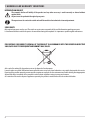
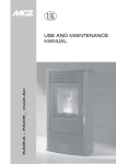
USE AND INSTALLATION MANUAL
EN
WOOD-BURNING STOVE
STRIPE OVERNIGHT
Translation of original instructions
8901177000
TABLE OF CONTENTS
TABLE OF CONTENTS................................................................................................... II
INTRODUCTION...........................................................................................................1
1-WARNINGS AND WARRANTY CONDITIONS..................................................................2
2-INSTALLATION INSTRUCTIONS...................................................................................5
3-DIMENSIONS AND TECHNICAL CHARACTERISTICS......................................................15
4-INSTALLATION AND ASSEMBLY................................................................................17
5-OPERATION............................................................................................................25
6-MAINTENANCE AND CLEANING................................................................................29
II
INTRODUCTION
Dear Customer,
thank you for having chosen a product from our Wood-burning range.
Products manufactured with OYSTER technology, do not consume the oxygen inside the room when installed correctly, thanks to a perfectly
sealed structure, but draw all the air from outside and can therefore be installed in any well-insulated home and in passive houses. This
technology eliminates all risks of smoke being released into the room and ventilation grilles are no longer required. Consequently, there
will be no more flows of cold air in the room, which make it less comfortable and compromise the overall efficiency of the system.
The sealed product can be installed in the case of forced ventilation or in a room in which there may be a negative pressure compared to
outside.
To allow for optimal product operation and for you to enjoy the warmth and sense of wellbeing that the fire can convey in
your home, we advise you to read this manual carefully before starting up the product for the first time.
REVISIONS TO THE PUBLICATION
The content of this manual is strictly technical and property of MCZ Group Spa.
No part of this manual can be translated into another language and/or altered and/or reproduced, even partially, in another form, by
mechanical or electronic means, photocopied, recorded or similar, without prior written approval from MCZ Group Spa.
The company reserves the right to make changes to the product at any time without prior notice. The proprietary company reserves its
rights according to the law.
CARE OF THE MANUAL AND HOW TO CONSULT IT
• Take care of this manual and keep it in an easily accessible place.
• Should the manual be misplaced or ruined, request a copy from your retailer or directly from the authorised technical assistance
Department.
• “Bold text” requires particular attention.
• “Text in italics” is used to draw your attention to other paragraphs in this manual or any additional explanation.
• “Note” provides the reader with additional information.
SIMBOLOGIA PRESENTE SUL MANUALE
ATTENTION:
carefully read and understand the relative message because failure to comply with that which is written can
cause serious damage to the product and put the user’s safety at risk.
INFORMATION:
failure to comply with these provisions will compromise the use of the product.
OPERATING SEQUENCES:
sequence of buttons to be pressed to access the menus or make adjustments.
MANUAL:
carefully read this manual or the relative instructions.
Technical Dept. - All rights reserved - Reproduction is prohibited
1
1-WARNINGS AND WARRANTY CONDITIONS
SAFETY PRECAUTIONS
• Installation, functional verification and maintenance must only be performed by qualified or authorised personnel.
• Install the product in accordance with standards in force in the relative place, region or country.
• This product is not intended for use by persons (including children) with reduced physical, sensory or mental
capabilities, or lack of experience and knowledge, unless they have been given supervision or instruction concerning
use of the product by a person responsible for their safety.
• Only fuel recommended by the company must be used. The product must not be used as an incinerator. It is strictly forbidden to use
liquid fuel.
• The user, or whoever is operating the product, must read and fully understand the contents of this instruction manual before
performing any operation. Errors or incorrect settings can cause hazardous conditions and/or poor operation.
• Do not use the product as a ladder or supporting structure.
• Do not place laundry on the product to dry. Any clothes horses or similar objects must be kept at a safe distance from the product.
Fire hazard.
• All liability for improper use of the product is entirely borne by the user and relieves the manufacturer from any civil and criminal liability.
• Any type of tampering or unauthorised replacement with non-original spare parts could be hazardous for the operator’s safety and
relieves the company from any civil and criminal liability.
• Most of the surfaces of the appliance can get very hot (door, handle, glass, smoke outlet pipes, etc.). Avoid contact with these
parts unless adequate protective clothing is worn or appropriate means are used, such as heat protective gloves or cold
handle systems.
• It is forbidden to operate the product with the door open or the glass broken.
• Switch the product off in the event of a fault or malfunctioning.
• Do not wash the product with water.
• Do not stand in front of the product for a long time. Do not overheat the room where the product is installed. This could affect your
physical conditions and cause health problems.
• Do not put any fuel other than wood in the hopper.
• Install the product in rooms that are adequately protected against fire and equipped with all the utilities such as supplies (air and
electricity) and smoke outlets.
• If a fire breaks out inside the chimney, switch the latter off and do not open the door. Then contact the competent authorities.
• The product and the ceramic cladding must be stored in a place where there is no humidity and must not be exposed to the elements.
• It is recommended not to remove the feet that support the product in order to guarantee adequate insulation, especially if the
flooring is made of flammable material.
• If the ignition system is faulty, do not force ignition with flammable materials.
• Special maintenance must only be performed by authorised and qualified personnel.
• Assess the static conditions of the surface on which the weight of the product will rest and provide suitable insulation if it is made of
flammable material (e.g. wood, fitted carpet or plastic).
• Avoid installing the product in rooms containing B-type gas appliances, hoods with or without an extractor, heat pumps or collective
ventilation ducts.
• Avoid having several chimneys running at the same time in the room or being close to a stairwell. Furthermore, make sure there are
no appliances in interconnected rooms, which when used simultaneously could cause a negative pressure in one of the two rooms.
• The product must be used in accordance with all the local and national laws and European Standards applicable in the relative place,
region or country.
• Do not use volatile and/or flammable substances (petrol, alcohol, etc.) to ignite the fire.
• Do not use fuel that could release toxic substances or pollutants.
• Do not use water to put the fire out.
• Check the external-internal air inlet and the chimney at least once a year and have them cleaned also.
2
1-WARNINGS AND WARRANTY CONDITIONS
INFORMATION
•
•
•
•
Please contact the retailer or qualified personnel authorised by the company to resolve a problem.
Check and clean the smoke outlet pipes regularly (connection with the chimney).
The product is not a cooking appliance.
Keep this instruction manual in a safe place as it must accompany the product throughout its working life. If it is sold or transferred
to another user, always make sure that the manual accompanies the product.
INTENDED USE
The product only works with wood and must be installed indoors.
WARRANTY CONDITIONS
The company provides a product warranty, excluding the parts subject to normal wear stipulated below, for a period of two years
from the date of purchase, which is proven by a supporting document that contains the name of the seller and the date when the sale took
place. Warranty cover is valid if the completed warranty is returned within 8 days and the product is installed and tested by a qualified
installer, according to the detailed instructions provided in the installation guide supplied with the product.
The term ‘warranty’ refers to the (free-of-charge) replacement or repairs of parts acknowledged to be faulty due to manufacturing
defects.
RESTRICTIONS
The above-mentioned warranty does not cover parts of electrical and electronic components and fans, which are covered for
two years from when the product is purchased, proof of which is provided as specified above. The warranty does not cover parts subject to
normal wear, such as: gaskets, glass and all parts that can be removed from the firebox.
Replaced parts will be covered by the warranty for the remaining period of the warranty in force as from the date of purchase of the product.
EXCLUSIONS
Variations in colour of the painted or ceramic parts and crazed ceramics do not constitute grounds for a claim as they are natural
characteristics of the material and product use.
The warranty does not cover any part that may be faulty as a result of negligence or careless use, incorrect maintenance or installation that
does not comply with the company’s instructions (see the relative chapters in this user manual).
The company declines all liability for any damage which may be caused, directly or indirectly, to persons, animals or objects as
a consequence of non compliance with all the prescriptions specified in the instruction manual, especially warnings regarding
installation, use and maintenance of the product.
If the product does not work correctly, contact your local retailer and/or importer.
Damage caused during transport and/or when handled is excluded from the warranty.
The supplied manual is the only reference for installation and product use.
The warranty will be rendered null and void in the event of damage caused by tampering, atmospheric agents, natural disasters, electrical
discharges, fire, defects in the electrical system and maintenance not being performed at all or as indicated by the manufacturer.
Technical Dept. - All rights reserved - Reproduction is prohibited
3
1-WARNINGS AND WARRANTY CONDITIONS
INTERVENTION REQUEST
The company declines all liability if the product and any other accessory is used incorrectly or altered without
authorisation.
All parts must be replaced with original spare parts.
The request must be sent to the retailer who will forward it to the technical assistance department.
SPARE PARTS
Only original spare parts must be used. The retailer or service centre can provide all the useful information regarding spare parts.
It is recommended not to wait for the parts to be worn before having them replaced. It is important to perform regular maintenance.
PRECAUTIONS FOR CORRECT DISPOSAL OF THE PRODUCT IN ACCORDANCE WITH THE EUROPEAN DIRECTIVE
2002/96/EC AND ITS SUBSEQUENT AMENDMENT 2003/108/EC.
At the end of its working life, the product must not be disposed of as urban waste.
It must be taken to a special differentiated waste collection centre set up by the local authorities or to a retailer that provides this service.
Disposing of the product separately prevents possible negative consequences for the environment and health deriving from inappropriate
disposal and allows its materials to be recovered in order to obtain significant savings in energy and resources.
As a reminder of the need to dispose of appliances separately, the product is marked with a crossed-out wheeled dustbin.
4
2-INSTALLATION INSTRUCTIONS
The requirements stipulated in this chapter refer to the regulations of the Italian installation standard UNI 10683. In any case, always
comply with the regulations in force in the country of installation.
THE OPERATING ENVIRONMENT
For correct operation and even distribution of heat, the product must be placed where the air required for combustion can flow, in
accordance with the installation regulations and the standards in force in the country of installation.
The volume of the installation environment must not be less than 25 m3.
The air must enter through permanent openings in the walls that reach outside with a minimum section of 100 cm2 in the case of a nonOyster installation, i.e. without external ducted combustion air.
These openings must be made in such a way that it is impossible for them to be obstructed in any way.
Air can also be drawn from adjacent rooms to the one that is to be ventilated, provided they have an external air inlet and are not used
as a bedroom or bathroom or where there is a fire hazard, such as: a garage, wood shed or where flammable materials are stored, and
applicable regulations must be strictly complied with.
• If the product is placed too close to the wall it could cause overheating and damage the plaster (yellowing,
cracking, etc.).
• The product must be connected to a flue or a vertical duct that can expel the smoke at the highest point of the
building.
• The product must be connected to a flue or an internal or external vertical duct in compliance with current
regulations.
• The smoke derives from the combustion of wood essence and if it comes in contact with or close to walls, the
latter can become dirty.
• The external air inlet must be drilled before positioning the product (except in the case of installation with
Oyster technology).
• The floor of the room where the product will be installed must be adequately sized to withstand its weight.
POSITIONING
In the case of simultaneous installation with other heating appliances, provide appropriate air inlets for each one (according to the
instructions of each product).
The product cannot be installed in the following places (except for sealed or closed operation appliances with
external ducted combustion air intake):
• in bedrooms or bathrooms;
• in rooms where there are liquid fuel appliances with continuous or intermittent operation that draw the
combustion air from the room they are installed in;
• in rooms where there are B-type gas heating appliances, with or without domestic hot water production and
interconnecting rooms;
• where another heating appliance is installed without an independent air flow.
It is forbidden to place the product in an explosive atmosphere.
Technical Dept. - All rights reserved - Reproduction is prohibited
5
2-INSTALLATION INSTRUCTIONS
SAFE DISTANCES
Non-flammable walls
Flammable walls
A = 5 cm
B = 10 cm
A = 5 cm
B = 20 cm
STRIPE OVERNIGHT
*LEAVE AN APPROPRIATE DISTANCE FROM THE WALLS IN ANY CASE FOR MAINTENANCE TO BE PERFORMED ON THE PRODUCT.
If particularly delicate objects are present, such as furniture, curtains or sofas the distance of the product must be significantly
increased.
If the floor is made of wood, it is recommended to place a floor protection in accordance with the standards in force
in the country of installation.
Heat-sensitive or flammable objects cannot be placed near the product. Keep such objects at a minimum distance of
100 cm from the outermost point of the product.
6
2-INSTALLATION INSTRUCTIONS
CONNECTING THE COMBUSTION AIR INLET PIPE
The combustion air inlet does not necessarily have to be connected to the outside; this is only required if you wish to use Oyster
technology.
Always use pipes and fittings with appropriate seals that guarantee tightness.
REAR VIEW OF THE STRIPE PRODUCT:
1) COMBUSTION AIR INLET
Products manufactured with Oyster technology do not consume the oxygen inside the room, thanks to a perfectly sealed structure, but
draw all the air from outside and can therefore be installed in any well-insulated home and in passive houses.
In order to satisfy these requirements, the 80 mm diameter smoke duct for the combustion air inlet must be connected to the outside
of the building.
The product must be connected to the external air inlet with pipes and fittings that guarantee tightness in order to
comply with the sealed product requirements (OYSTER technology).
Technical Dept. - All rights reserved - Reproduction is prohibited
7
2-INSTALLATION INSTRUCTIONS
OUTDOOR AIR INLET
Drill a hole on the outer wall close to the product with a minimum section of 100 cm² (13 cm in diameter or 12x12 cm if square, considering
the protective grids), protected by a grid on the outside.
The air inlet must also:
• be protected with a grid, metal mesh, etc. without reducing the net section;
• be positioned in such a way so as not to be obstructed;
• allow maintenance to be performed;
• be directly interconnected with the room where the product is installed;
• in the case of ducting, up to 3.5 linear metres, increase the cross-section by about 5%, whereas for longer ducts, increase it by 15%.
Remember that the ventilation grilles always have a useful section in cm2 on one side.
When choosing the grille and size of the hole, check that the useful section of the grille is larger or equal to the
section required by the manufacturer for product operation.
IMPORTANT!
The air flow can also be drawn from an adjacent room to that of the room where the product is installed, provided
the air can flow freely through permanent openings interconnected with the outside; it is forbidden to connect to
thermal units, garages, kitchens or bathrooms.
CONNECTION TO THE CHIMNEY
The connection to the chimney is very important and must be implemented carefully. The products have an upper or rear smoke exhaust.
The smoke exhaust pipe must be assembled in such a way so as to guarantee its tightness during product operation in negative pressure
and prevent condensation from being formed and conveyed towards the product.
Any manual draught adjustment devices inserted in the pipe must not hermetically close the internal section of the duct. These dampers
must be equipped with a suitable mechanism to prevent the valve from rotating completely in the closed position. The minimum safety
opening surface must be 3% of the through section and not less than 20 cm². If the smoke duct has a horizontal section, this must rise
with a minimum gradient of 3-5% (3-5 cm per metre).
EXAMPLE OF CONNECTION TO THE CHIMNEY
The horizontal section of the smoke duct must not be longer than 2 m.
It is forbidden to use flexible and fibre cement pipes. The smoke duct must not cross rooms in which it is forbidden to
install combustion appliances. It is forbidden to use counter-sloping pipes.
8
2-INSTALLATION INSTRUCTIONS
CONNECTING THE PRODUCT TO THE CHIMNEY
The smoke outlet pipe is designed by the company for the smoke to be expelled towards the top of the product.
There lies the possibility of having the smoke outlet on the back of the product by purchasing the rear smoke outlet fitting (see the
following paragraph).
Before installing the heat storage refractory kit, insert the optional smoke outlet fitting into the pre-assembled pipe on the product and
remove the knockout circle on the rear panel of the product.
REAR SMOKE OUTLET FITTING
KNOCKOUT HOLE
REAR SMOKE OUTLET WITH FITTING (OPTIONAL)
UPPER SMOKE OUTLET
Technical Dept. - All rights reserved - Reproduction is prohibited
9
2-INSTALLATION INSTRUCTIONS
TOP HOLE COVER AND REAR SMOKE OUTLET FITTING (ACCESSORY)
Since there lies the possibility of having the smoke outlet on the back, an accessory has been constructed (optional), which consists of the
smoke fitting and the tray.
The fitting, as mentioned in the previous paragraph, must be connected to the tube set-up in the product.
The top hole cover is part of the standard supply of the stove top and must be applied if a rear smoke outlet is used. It must be applied to
the hole designed for the vertical smoke duct.
SMOKE FITTING
10
TOP HOLE COVER
2-INSTALLATION INSTRUCTIONS
CHIMNEY
The chimney is the fundamental element for smoke expulsion and must therefore comply with the following requirements:
• Be waterproof and thermally insulated.
• Be made of suitable materials that resist mechanical stress over time, heat, the effects of the combustion products and any possible
condensation.
• Have a vertical set-up with deviations from the axis of no more than 45° and free of bottlenecks.
• Must be suitable for the specific operating conditions of the product and have the CE marking (EN1856-1, EN1443).
• Must be adequately sized for the draught/smoke expulsion requirements that are necessary for the product to operate correctly
(EN13384-1).
• The chimney must not be shared with other appliances.
• The chimney must be at least category T400 (or higher if required by the smoke temperature of the appliance) and soot-fire resistant.
Resistance to moisture is mandatory if this is required by chimney size.
• The internal section is preferably circular.
• In the case of a pre-existing product that has been used, it must be cleaned.
The chimney is fundamental for correct operation and safety of your product.
A
B
C
D
A) CHIMNEYPOT
B) CHIMNEY
C) SMOKE DUCT
D) EXTERNAL AIR INLET
TYPICAL CHIMNEY INSTALLED CORRECTLY WITH A
CHAMBER WITH SEALED DOOR AT THE FOOT OF THE
EXTERNAL RISING SECTION, TO COLLECT AND REMOVE THE
SOLID MATERIALS PRODUCED DURING COMBUSTION.
In the event of poor weather conditions for product operation (low pressure, external temperature not particularly
harsh, windy day), may lead to inverse draught in the chimney. In this case, it is recommended to use a little paper to
ignite the fire to heat the chimney and restore normal draught. Then proceed with normal product start-up.
Technical Dept. - All rights reserved - Reproduction is prohibited
11
2-INSTALLATION INSTRUCTIONS
EXAMPLES OF CHIMNEYS
AISI 316 steel chimney with
double chamber insulated
with ceramic fibre or similar
material, resistant to 400°C.
Refractory chimney with Traditional square-section clay
insulated double chamber and chimney with insulating empty
external lightweight concrete inserts.
cladding with cellular material
such as clay.
Avoid chimneys with an
internal rectangular section
where the larger side is 1.5
times the smaller side (such as
20x40 or 15x30).
EXCELLENT
GOOD
VERY POOR
POOR
For square or rectangular-section chimneys, the internal corners must be rounded with a radius of no less than 20 mm. For a rectangular
section, the ratio between internal dimensions must be ≤1.5.
The sections/lengths of the chimneys shown in the technical data table are guidelines for a correct installation. Any alternative
configurations must be suitably sized in accordance with the general method of calculation of UNI EN13384-1.
It is recommended for the flue duct to be equipped with a chamber to collect solid materials beneath the opening of the smoke duct,
which can be easily opened and inspected through an airtight door.
Should doubts arise regarding chimney performance or if its dimensions are different from those recommended, you
are strongly advised to have an installer, authorised by the manufacturer, perform an inspection and evaluate the
performance of the chimney.
The manufacturer declines all liability regarding product malfunctioning if this is attributable to a chimney that is
badly sized and installation does not comply with the stipulated requirements.
12
2-INSTALLATION INSTRUCTIONS
CHIMNEYPOT
Often, if this factor is underestimated it hinders smooth “chimney system” operation.
The draught of the chimney also depends on its chimneypot.
In the case of an artisan product, it is very important for the four expulsion sections to be more than twice the internal section of
the chimney.
The chimneypot will be exposed to the four winds and it is therefore recommended for it to be specifically designed to
withstand the elements (e.g. an industrial chimney).
INDUSTRIAL CHIMNEYPOT WITH
PREFABRICATED STACKED ELEMENTS. ALLOWS
EXCELLENT SMOKE EXPULSION.
TRADITIONAL ARTISAN CHIMNEYPOT.
THE CORRECT EXPULSION SECTION MUST BE AT
LEAST TWICE THE INTERNAL SECTION OF THE
CHIMNEY; IDEALLY 2.5 TIMES ITS SIZE.
CHIMNEYPOT FOR A STEEL CHIMNEY WITH
AN INTERNAL CONE AND SMOKE DEFLECTOR.
ALLOWS EXCELLENT SMOKE EXPULSION.
B
1 mt
A
0,5 mt
The chimneypot must comply with the following requirements:
• Have an internal section equal to that of the chimney.
• Have a useful outlet section that is at least double that of the internal section of the chimney.
• Be constructed in such a way so as to prevent rain, snow and any foreign body from entering the chimney.
• Be positioned so as to ensure adequate smoke dispersion and in any case beyond the reflux area in which counter pressure is likely
to form.
YES
NO
A) UPPER STOREY OR SOLID
COMBUSTIBILITY.
B) LOWER STOREY.
Technical Dept. - All rights reserved - Reproduction is prohibited
13
2-INSTALLATION INSTRUCTIONS
In the case of paired chimneys, the solid combustibility or upper storey chimneypot must be at least 50 cm higher than the
others in order to prevent the pressure from being transferred between the paired chimneys.
The chimneypot must not have any obstacles within a range of 10 metres, such as walls, slopes and trees. In this case, raise
it at least 1 m above the obstacle and in the case of other chimneypots nearby, leave a gap of at least 2 m. In any case, the
chimneypot must exceed the highest point of the roof by at least 1 m or be above the reflux area, which is equal to 130 cm
in roofs with a gradient greater than 10° (perpendicular height to the surface of the roof).
14
3-DIMENSIONS AND TECHNICAL CHARACTERISTICS
STRIPE OVERNIGHT STOVE
* DIAMETER OF THE SMOKE OUTLET
Technical Dept. - All rights reserved - Reproduction is prohibited
15
3-DIMENSIONS AND TECHNICAL CHARACTERISTICS
TECHNICAL CHARACTERISTICS
STRIPE OVERNIGHT
Type of fuel
Wood - logs
Hourly consumption
2,0 kg/h – 0,9 kg/h
Reloading/load time
45’/1,5 kg
Nominal output power
kW 7,2/Kcal 6192
Minimum output power
kW 3,5/Kcal 3010
Efficiency
83,1%
CO emission in the smoke (13% O2)
0,09%
Particulate/OGC/Nox (13%O2)
33,3 mg/Nm3 (13% O2)/ 69 mg/Nm3- 115 mg/Nm3
Smoke flow rate
6,9 g/s
Smoke temperature
230 °C
Recommended draught
12 Pa / 0,12 mbar
Heatable volume m3
151/40 – 172/35 – 201/30 *
Smoke outlet
Ø 15 cm
Firebox dimensions
H=430 mm P=240 mm L=350 mm
Net weight
125 kg stove + kg 65 storage
External combustion air inlet
100 cm2
Chimney
Chimney section
18x18 cm Ø18
Minimum chimney height
4m
Notes
* These data may vary according to the type of fuel used.
The stove is an intermittent combustion appliance.
Tested according to EN 13240 in accordance with Directive 89/106/EEC (Construction Products).
16
4-INSTALLATION AND ASSEMBLY
IMPORTANT!
The product must be installed and connected to the chimney by a qualified technician or competent personnel in
order for all local or national regulations to be complied with and in any case in accordance with UNI 10683.
When the product and the relative frame are unpacked, verify that every part is in perfect working order and no damage has been caused
during transport. If the product is installed in a place that is difficult to access, the weight can be reduced by removing the internal
elements of the firebox. It is recommended to set each element back in place correctly.
PREPARATION AND UNPACKING
The product is delivered on pallets with various packaging.
• One contains the structure of Fig. 1.
• A pallet containing the refractory parts, the cardboard box containing the sides and the box containing the top Fig.2.
Open the package and remove the boxes. Once the package is open, remove the two brackets that block the product to the pallet (Fig. 3).
Remove the two screws A and the other three screws B that block the bracket to the pallet and set the product in the pre-selected place,
making sure this complies with the requirements.
FIG. 1 - STRIPE PACKAGE
FIG. 2 - PACKAGE OF REFRACTORY PARTS
AND BOX WITH SIDES AND TOP
FIG. 3 - REMOVING THE PACKAGE SCREWS
Technical Dept. - All rights reserved - Reproduction is prohibited
17
4-INSTALLATION AND ASSEMBLY
The product must always remain in a vertical position and handled solely with a forklift. Pay particular attention to the door and its glass,
protecting them from mechanical knocks that would compromise their integrity.
In any case, the product must always be handled with care. If possible, unpack the product near the place of installation.
The packaging materials are neither toxic nor harmful, and therefore no particular disposal measures are required. The end user is
responsible for product storage, disposal or possible recycling in compliance with the relative applicable laws.
ASSEMBLING AND ADJUSTING THE FEET
The product requires the support feet to be assembled, whose function is to adjust the product level for it to be aligned and stable on the
ground. The feet are screwed to the base of the structure and they can be applied as shown in the figure and adjusted with a screwdriver
by acting on the head of the feet.
For an effective closing function of the doors, adjust the feet for there to be a difference of 2 mm between the front and rear of the base
(see figure).
A = B+2 MM
A
B
ASSEMBLING THE STORAGE PANELS
The storage parts can now be assembled.
The storage consists of:
STORAGE
A
B
C
D
E
F
NO. OF ITEMS
4
4
1
1
2
1
18
4-INSTALLATION AND ASSEMBLY
Proceed with the installation as follows:
• Place the two parts E on the base of the smoke fitting.
• Place part F on the upper part of item E.
• Place part D on the right side of part E and part C on the left side.
Place the following on top of these parts, which form the base:
• Part A (4 items in all).
• Part B interlocks on part A (4 items in all).
SIDE VIEW
FRONT VIEW
Technical Dept. - All rights reserved - Reproduction is prohibited
REAR VIEW
19
4-INSTALLATION AND ASSEMBLY
ASSEMBLING THE SIDE CLADDING
The metal sides are not particularly difficult to install. The main precaution is to install the sides of the product only when the latter is set
in place. Moving the product with the sides assembled might damage the flooring.
Firstly, place the front panel (with the hole for the door) on the structure of the product with the side holes of the panel in line with the
holes on the structure of the product. Open the stove door to place the fron panel in its housing (FIG.A).
Fasten the panel with the three screws on the right and the three screws on the left.
IMPORTANT:
When you place the front panel on the structure it is necessary to match the knob up with the hole in the panel.
INTERNAL PANEL
FIG.A
PANEL FASTENING
FRONT PANEL FASTENING
20
HOLE IN PANEL
KNOB
4-INSTALLATION AND ASSEMBLY
Then bring the two profiles near the front panel making sure the flap of the panel enters the seat on the profile.
HOUSED PROFILE
PROFILE TO BE BROUGHT NEAR
THE FRONT PANEL
Before installing the rear panel, centre and fasten the air adjustment knob. Hold the knob in line (frontally) with one hand and fasten the
screw from behind the stove with the other.
Technical Dept. - All rights reserved - Reproduction is prohibited
21
4-INSTALLATION AND ASSEMBLY
Then bring the rear panel and enter it in the pins found on the lower part of the product.
PINS
22
4-INSTALLATION AND ASSEMBLY
Once the above is completed, block the front and rear panels and profiles with the two fastening plates.
As shown in the figure, fasten the plate (one on the right and the other on the left) with the two screws in the holes on the front and rear
panels. The plate must slide into the top part, under the two edges of the front and rear panel and then fastened from the top with the
two screws.
Technical Dept. - All rights reserved - Reproduction is prohibited
23
4-INSTALLATION AND ASSEMBLY
ASSEMBLING THE TOP
Place the top on the upper part of the product making sure the spacers on the bottom part of the top enter the holes on the structure.
TOP
SPACERS OF THE TOP
BOTTOM VIEW OF THE TOP
24
5-OPERATION
START-UP PRECAUTIONS
Make sure you have read and fully understood the contents of this instruction manual.
Remove all components that could burn from the firebox and door (instructions and various adhesive labels).
Remove the stickers from the ceramic glass otherwise the high temperature could melt them and cause irreparable damage to the glass.
The product can be positioned at an angle or against the wall.
Avoid touching the product during the initial start-up, as the paint completes its drying process and hardens during
this phase. It is good practice to guarantee effective ventilation in the room during the initial start-up, as the
product will emit some smoke and smell of paint, which is absolutely normal!
If necessary, touch up the paint with the spray can of the specific colour.
Do not stand close to the product and air the room. The smoke and smell of paint will disappear after about an hour of operation, however,
remember they are not harmful in any case.
The product will be subject to expansion and contraction during the start-up and cooling phases, therefore light
creaking noises may be heard.
This is absolutely normal as the structure is made of laminated steel and must not be considered a defect.
It is extremely important to make sure the product is not immediately overheated and the temperature increases
gradually.
This will prevent damaging the welds and the steel structure.
Do not expect heating efficiency immediately!
FUEL
FUEL: Wood
In order to achieve maximum efficiency from your product, it is of utmost importance to use wood with adequate characteristics.
Oak-beech-ash-locust wood or logs of non-resinated pressed logs can be used.
The latter have a high calorific value and must be used with caution to avoid overheating that could damage the product.
Fuels such as poplar-pine-linden-chestnut have a low calorific value as the wood is soft. Moisture content is fundamental for all the listed
types of wood.
Wood drying time
(e.g. beech)
Moisture
%
Calorific power
Kcal/h
Freshly cut
50
/
3 Months
40
2410
6 Months
35
2700
9 Months
30
2900
12 Months
25
3150
15 Months
20
3400
18 Months
15
3710
21 Months
10
3980
Technical Dept. - All rights reserved - Reproduction is prohibited
25
5-OPERATION
A high percentage of moisture causes condensation in the smoke duct, thereby causing an alteration to the draught and
generating smoke and considerable soot deposits in the firebox, on the glass of the door and on the chimney, with the
subsequent risk of this catching fire. It also leads to a much lower overall efficiency.
Damp or treated wood releases more smoke than usual, which could dirty the glass more quickly. Poor chimney performance
can also compromise the cleanliness of the glass, as the smoke remains in the combustion chamber longer than usual.
Do not use treated fuels (painted or lacquered wood) or non-compliant fuels (plastic or derivatives), which could
release toxic substances or pollutants.
Do not burn waste.
The gases produced by combustion of unsuitable fuel could damage the product, the chimney and pollute and
compromise your health.
USING THE STOVE
OPENING/CLOSING THE DOOR
The product is equipped with automatic door closure. Use the leather glove supplied to pull the handle towards you to open the door.
Simply let go of the handle and the door will close automatically.
NOTE: for the door closing system to work properly, the product must be installed according to the feet adjustment guidelines in Chap. 4.
FUEL LOADING
To load the fuel, simply open the door by lifting and pulling the handle towards you.
The metal parts and the glass become very hot during operation, therefore use adequate protection.
The door to the combustion chamber must remain closed during combustion.
It is forbidden to load larger amounts of fuel than those specified in the technical data sheets of each individual
product.
An excessive amount of fuel in the combustion chamber could damage and deform the firebox and the structure of
the product.
The company cannot be held liable for any damage caused by fuel overloads or if non-compliant fuel is used.
COMBUSTION CONTROL
Combustion and therefore the combustion air intake is controlled via a single control knob.
The inlet air is either:
PRIMARY AIR:
the primary air is pre-set and is mainly delivered to help the ignition process of the product.
SECONDARY AIR:
the introduction of secondary air is pre-set and is used for the partial cleaning of the glass and allows the completion of the combustion
process. Thanks to this process, heating performance and efficiency of the product are enhanced.
26
5-OPERATION
ADJUSTING THE AIR WITH THE PUSH-PULL SYSTEM
Press the air adjustment knob, which will slightly emerge from its seat thanks to a spring and it can then be turned to the left or right
according to the increase or decrease in combustion air that is to enter the combustion chamber.
The primary and secondary air intake is pre-set; the primary and secondary air intake is adjusted by moving the knob.
Once the adjustment is complete, the knob is pressed once again for it to enter its seat.
AIR ADJUSTMENT KNOB POSITIONS 1-2-3
AIR ADJUSTMENT KNOB IN POSITION 2
PRIMARY AIR KNOB (TURNED TO THE LEFT)
The knob turned to the left (i.e. counter-clockwise) in pos. 3 is designed to bring a large amount of air into the firebox, to allow a rapid
and effective ignition of the fire.
SECONDARY AIR KNOB (IN POSITION 2)
Secondary air, as mentioned above, allows the combustion process to be completed and enhances efficiency (knob in pos. 2).
The position of the knob determines the nominal output, thereby minimising the primary and secondary air intake.
KNOB TURNED TO THE RIGHT
Turn the knob clockwise to position 1 in order to decrease the amount of air in the combustion chamber as only a minimum amount of
primary air is drawn.
This position is used to prolong combustion (for instance, at night, or when you are not at home) so that the product is set to minimum,
the fire is kept on while achieving savings on fuel.
Technical Dept. - All rights reserved - Reproduction is prohibited
27
5-OPERATION
FIRST IGNITION
A NOTE REGARDING PAINT EXHALATION
It is recommended to air the room before the first start-up to evacuate any smells and/or fumes emitted by the paint during the drying
and hardening phase due to the heat.
Do not stand close to the stove and air the room. The smoke and smell of paint will disappear after about an hour of
operation, however, remember they are not harmful in any case.
It is recommended to first start-up the product with caution, using fine and seasoned wood.
The combustion air inlet must be completely open. When combustion has started, normal sized wood can be introduced. The flame
must be as laminar as possible.
Each time the wood is loaded, the door must be opened slowly to prevent smoke blow back in the room.
Proceed as follows:
• Place a small ball of scrunched up paper into the product.
• Cover the paper with a few twigs and a few pieces of wood.
• Turn the lever completely to the left (pos. 3).
• Light the paper and if necessary keep the door ajar for a few minutes until the combustion chamber and the flue begin to warm up.
• The door can be closed once the twigs start to burn.
As the fire gradually burns, add wood. Never overload the product with wood (see the technical data in the table).
As soon as the flames have died down and a bed of embers has formed, load the product normally.
Small loads are preferable to large loads of wood for combustion.
It is recommended to adopt this fuel loading method also in subsequent product use.
To achieve the nominal output and optimal combustion, load the amount of wood and comply with the loading
interval indicated in the technical data table (Chapter 3).
28
6-MAINTENANCE AND CLEANING
All the cleaning operations of all parts must be performed with a completely cold product.
CLEANING PERFORMED BY THE USER
CLEANING THE GLASS
The glass can be cleaned with specific products (see our price list), a cloth soaked in a water and ammonia solution or a little white ash and
a sheet of newspaper. It takes longer to clean if there is any soot build-up and dirt.
Do not spray the cleaning product on to the painted parts or the seals of the door (ceramic fibre cord).
The ceramic glass installed on the manufacturer’s products have a heat resistance of approximately 750°C and are
tested and checked before and after assembly to check for any cracks, bubbles and swelling.
Despite the high resistance to temperature, the glass is a fragile element and it is therefore recommended to handle
the door carefully without slamming or forcing it. The glass can break as it is not a flexible element.
Moreover, this type of glass does not shatter or burst and should it break, for the above reasons, only a crack will
form.
CLEANING THE UPPER CALORITE DEFLECTORS
They require no special care. Even though the internal deflectors of the combustion firebox are made of effective yet porous material, they
must be replaced after prolonged use due to wear, damage caused when their thickness is reduced to half or broken.
CLEANING THE ASH
This must be performed with the product turned off; it is recommended to thoroughly clean the ash pan to ensure correct combustion.
Open the door, remove the grille and the ash pan using the supplied cold handle.
Clean also any ash deposits in the pan compartment.
Hot ashes must be stored outside with utmost care and not thrown into the dustbin. Allow them to cool down in the open
air in a metal container.
Technical Dept. - All rights reserved - Reproduction is prohibited
29
6-MAINTENANCE AND CLEANING
CLEANING STAINLESS STEEL AND SATIN-FINISHED SURFACES
These surfaces do not usually require any specific treatment besides not being cleaned with abrasive materials. It is recommended to clean
stainless steel and satin-finished surfaces with a paper towel or a dry, clean cloth soaked in nonionic surfactant-based detergent (<5%);
a spray cleaner for glass and mirrors can also be used.
CLEANING PAINTED PARTS
Avoid cleaning the painted parts with damp cloths when the product is on or hot so as to prevent thermal shock of the paint and its
consequent detachment. Do not use abrasive or aggressive materials or products. Clean with a paper towel or damp cotton cloth.
The silicone paints used to coat the products have top quality technical properties that allow for resistance to very
high temperatures.
However, there is a physical limit (380°- 400°) beyond which the paint loses its characteristics and begins to “whiten”
or “vitrifies” (over 450°) and can flake and peel off the steel surface. If this occurs, temperatures well above those
at which the product should operate have been reached. It is therefore recommended to use the amount of fuel
specified in the technical tables.
CLEANING THE CHIMNEY
Mechanical cleaning of the chimney is mandatory at least once a year; excessive unburned waste can cause problems when the smoke is
expelled and start a fire in the flue itself.
CLEANING TO BE PERFORMED BY QUALIFIED PERSONNEL
ATTENTION:
the frequency with which the product is to be cleaned is based on its use and the type of installation. The company
recommends contacting an authorised service centre for end-of-season maintenance and cleaning to be performed
on the entire flue system as the above-mentioned operations will also be performed together with a general
inspection of the product.
EMERGENCY
If for any reason the fire in the combustion chamber must be put out suddenly and quickly or a fire has ignited in the chimney, act as
follows:
• Time permitting, remove the embers and ashes using a metal container.
• Request immediate help from the relative organisations.
30
MCZ GROUP S.p.A.
Via La Croce n°8
33074 Vigonovo di Fontanafredda (PN) – ITALY
Telephone: 0434/599599 r.a.
Fax: 0434/599598
Internet: www.mcz.it
e-mail: [email protected]
For further technical information
regarding installation or operation please contact the
TECHNICAL ASSISTANCE – AFTER-SALES DEPARTMENT
Monday to Friday
8.00 to 12.00 and 14.00 to 18.00
8901177000
REV.0
07/09/2012