1
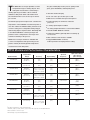
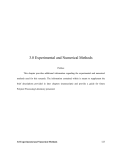
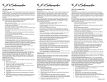
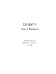
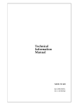
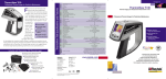
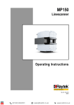
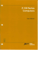
RAYTEK PROCESS IMAGING SERIES
MP50
Datasheet
Thermal Imaging for Industrial Applications
MP50 Process Imager™
The MP50 allows you to visualize and measure the
temperature distribution of virtually any process or product
T
The glass model (G5) ensures process quality on flat
he MP50 Process Imager provides accurate
glass, glass windshields, and tempering lines.
temperature images of moving objects. This
multi-point measurement is achieved by a
rotating optical system which collects infrared
■
Real-time thermal imaging
The motorized mirror scans at rates up to 48 lines
■
Fast scan rates up to 48 lines per second
per second.
■
Wide choice of models and spectral responses
An internal high speed microprocessor calculates the
■
Thermal imaging for continuous or discrete
processes
■
3 analog signal outputs included
■
16 analog output D/A interface card for PC available
■
Versatile DTMP™ Windows software
■
SoftSector Software (optional) allows measuring up
to 16 sectors
■
OPC software server interface available
■
Rugged NEMA12/IP65 enclosure;
built-in provision for air-purge/water-cooling
radiation at 256 points within a 90º field-of-view.
temperature of the individual measurement points of
each line of data. The MP50 includes provision for air
or water cooling, three configurable analog outputs,
®
and two-way digital communications. DataTemp MP
®
is an industrial Windows software package that
provides remote configuration of the imager and
real-time monitoring of the process.
MP50 Process Imager models are available with
a choice of temperature and spectral ranges. The
plastics models (P3 and P7) provide temperature
measurement on thin film plastic.
MP50 Models and Performance Characteristics
Model Number
Temperature
Range
Accuracy
Repeatability
4
4
Spectral
Response
Optical Resolution
90% Energy
(50% Energy)
RAYTMP50LT
20–350°C
(68–662°F)
±2ºC
(4ºF)
±1ºC
(2ºF)
3–5 µm
100:13
(300:13)
RAYTMP50MT
100–800°C
(212–1472°F)
±3ºC
(6ºF)
±2ºC
(4ºF)
3.8–3.9 µm
100:13
(300:13)
RAYTMP50G50
100–600°C
(212–1112°F)
±0.5% of measured
value or ±3ºC (6ºF)
whichever is greater
±1ºC
(2ºF)
4.5–5.2 µm
100:13
(300:13)
RAYTMP50G51
200–950°C
(392–1742°F)
±0.5% of measured
value or ±3ºC (6ºF)
whichever is greater
±1ºC
(2ºF)
4.5–5.2 µm
100:13
(300:13)
RAYTMP50P301
30–250°C
(86–482°F)
±3ºC
(6ºF)
±1ºC
(2ºF)
3.36–3.48 µm
33:1
(100:1)
RAYTMP50P311
100–350°C
(212–662°F)
±3ºC
(6ºF)
±1ºC
(2ºF)
3.36–3.48 µm
60:1
(180:1)
RAYTMP50P72
120–450°C
(248–842°F)
±3ºC
(6ºF)
±2ºC
(4ºF)
7.6–8.3 µm
25:1
(75:1)
RAYTMP501M
600–1200°C
(1112–2192°F)
±0.5% of measured
value or ±3ºC (6ºF)
whichever is greater
±2ºC
(4ºF)
0.9–1.0 µm
100:13
(300:13)
RAYTMP502M
400–950°C
(752–1742°F)
±0.5% of measured
value or ±3ºC (6ºF)
whichever is greater
±2ºC
(4ºF)
1.6 µm
100:13
(300:13)
1
Thin film, polyethylenes, and related materials
Thin film, acrylic, acetate, Teflon®, nylon, PVC, FEP, polyester, and related materials
3
At focus distance for each spot
4
At mid-range of specified temperatures
2
1
Standard Package
Components
General Specifications
Environmental Area Classification
NEMA 12, (IEC 529, IP 65)
Ambient Operating Temperature
without water cooling
with water cooling
0–50ºC (32–122ºF)
180ºC (356ºF) maximum
Internal Operating Temperature
0–60ºC (32–140ºF)
Maximum Temperature
65ºC (140ºF)
operating or non-operating
Relative Humidity
10% to 90%, non-condensing
Shock
IEC 68-2-29, 3-axes,
1000 bumps 5 G operating;
25 G non-operating
Vibration
IEC 68-2-6, 3 axes,
10–150 Hz
Operating: 0.5G
Non-operating: 2.0 G
Scan Motor
max water pressure
max air pressure
■
■
2
Built-in; included with
standard MP50
5 bar (72.5 psig)
3 bar (43 psig)
Size
(200 x 180 x 190 mm)
(7.9 x 7.1 x 7.5 inches)
Weight
7.0 kg (15.4 lbs)
Warm-up Time
20 minutes
Field of view (all models)
45º or 90º (selectable)
DataTemp MP Software (CD-ROM)
User Manual, Protocol Manual, DataTemp MP Manual
included on the DTMP CD-ROM
■
For RS-485:
1x 7.5 m (24.6 ft) RS-485
RS-485/RS-232 converter
1x SUB-D connector cable,
25-pin (male) to 9-pin (female)
■
RS-485 extension cable (accessory):
2x housing for SUB-D pin connectors
1x SUB-D connector (male) 25-pin
1x SUB-D connector (female) 25-pin
■
Power Supply Cable: 1x 7.5 m (26.4 ft)
■
Tools:
1x hex key wrench 2.5mm 1x hex key wrench 5mm
1x connector (female) 6-pin for digital inputs/outputs
1x connector (male) 4-pin for analog outputs
40,000 hours MTBF
Air Purge and Water Cooling
1
MP50 Process Imager Package Includes:
Electrical Specifications
Outputs
Analog
1
The air purge system produces a laminar air flow that protects the MP50 window from dust, moisture, and vapors.
Purged air exists through side slits near the MP50 window.
The air flow rate should be between 100 l/min (3.53 cfm)
and 200 l/min (7.06 cfm) through each side, which corresponds to a pressure between 0.5 bar (7.25 psig) and 3.0
bar (43 psig) when using the supplied metric fittings. Use
only clean or “instrument grade” air (free from oil contaminants). Do not use cooled air, which could cause condensation on the MP50 window.
3 user-configurable 0/4-20mA
current outputs, collectively isolated.
maximum dc resistance 500 ohms
Alarm
Electromechanical relay 30V, 1A
Digital
Communications
RS485/RS232 full duplex,
non-addressable
Inputs
Trigger + 5VDC pulse (user-supplied)
RS485/RS232
Power
Requirements
24 VDC ± 25%, 1A
CE Conformance
EN61010-1
EN61326-1
Operating Characteristics
2
Water cooling allows operation in ambient temperatures
up to 180ºC (356ºF). To avoid condensation, do not use
water colder than 15ºC (60ºF). With a water temperature
between 15ºC (60ºF) and 30ºC (86ºF) and a flow rate of
about 1 l/min (0.26 gallons/min), the housing internal temperature remains below 50ºC (122ºF). Using 30ºC (86ºF) a
water flow rate of 2 l/min (0.52 gallons/min) is necessary.
Use filtered water to prevent mineral deposits at the hose
couplings.
2
Scan Rate/
Response Time
48 Hz/21 mSec (analog outputs
and 45º FOV not operable)
36 Hz/28 mSec (analog outputs
and 45º FOV operable)
Focus Distance
1.5m (60 inches) standard; custom
focus distances (consult factory)
Emissivity
0.1 to 1.00 digitally adjustable
Number of Samples
256 per scan line (45º or 90º FOV)
Optical Diagrams
60
90
120
2.92
200
5.32
1.85
1" at 60"
0.91
D : S = 60 : 1
Focal Point
23
135
41
57
25 mm at 1,52 m
1.00
0.50
1.50
2.00
2.50
292
73
3.00
5.00
Distance: Sensor to Object D [inches]
Spot Diameter S
[inches]
30
394
11.5
Spot Diameter S
[mm]
Spot Diameter S
[mm]
Spot Diameter S
[inches]
Distance: Sensor to Object D [inches]
10.00
30
3.6
1.2
D : S = 25 : 1
Focal Point
32
40
78
120
394
200
7.1
3.2
1.72
1.03
20
D : S = 100 : 1
Focal Point,
Standard Focus 1.52 m
0.59" at 60"
17
23
0.50
1.00
1.50
80
33
15 mm at 1,52 m
43
2.00
2.50
Spot Diameter S
[mm]
0.71
3.00
100
58 mm at 1,52 m
1.00
0.50
1.50
2.50
2.00
124
3.00
180
5.00
Distance: Sensor to Object D [inches]
Spot Diameter S
[inches]
Spot Diameter S
[inches]
Spot Diameter S
[mm]
90
120
4.8
Distance: Sensor to Object D [m]
Distance: Sensor to Object D [inches]
60
90
2.28" at 60"
Distance: Sensor to Object D [m]
30
60
10.00
30
60
90
120
3.8
2.8
1.8" at 60"
1.1
D : S = 33 : 1
Focal Point
25
31
60
45 mm at 1,52 m
0.50
1.00
1.50
2.00
77
2.50
Distance: Sensor to Object D [m]
Distance: Sensor to Object D [m]
Mounting Considerations
L=Scan line width
D=Distance to target
(measured from front surface of housing)
90 deg FOV:
D=L/2-55mm
(D=L/2-2.2 in.)
45 deg FOV:
D=L/0.8284-55mm
(D=L/0.82484-2.2 in.)
FOV
D
90°
L
3
94
3.00
Accessories
Mounting Base for Tripod
XXX TMP50ACMP
Adjustable Mounting Bracket
XXXTMP50ACMB
80
(3.15)
50
(1.97)
A
124.5
(4.9)
5 (.2)
15 (.6)
360° pivot
M6
1/4-20-UNC 2B
63.5
(2.5)
50.8
(2)
Ø 7.1 (0.28)
76.2
(3)
60
(2.36)
25.4 (1.00)
70 (2.76)
90 (3.54)
Ø 7.1 (0.28)
38.1
(1.5)
M6
Ø 6,5 (0.26)
118.1
(4.65)
A-A
100 (3.94)
112 (4.41)
30°
A
DTMP Software
Mountings and Fittings
Process Imager Mounting Locations and Dimensions
Software DTMP
CD ROM (includes DTMP software,
DTMP Operators Manual, MP50
Operators Manual, and MP50
Protocol Manual)
Signal Processing
MAX, MIN, AVG, Peak/Valley Hold,
Alarm Setpoints
55
(2.17)
70
(2.76)
180
(7.09)
150
(5.91)
(Mounting dimensions are the same for top and bottom view)
100
(3.94)
All mounting threads are
4x M6
8 mm (0.31) deep
(front side, upside, below)
Process Imager Fittings Locations and
Dimensions
100
(3.94)
Water connection (out)
2x ISO228 G1/8"
threaded hose fitting
for internal hose
diameter of 6 mm (0.24 in)
Current outputs
OUT1 - OUT3
Minimum Requirements
■
600 MHz or higher Pentium III
■
128MB RAM
■
Mouse
■
SVGA monitor
■
4MB video RAM
■
800 x 600 resolution minimum with 64K colors
(high color 16-bit, higher resolution required for multiple
linescanners)
■
2 GB hard drive
■
Windows® NT4.0 or Windows® 2000
and Internet Explorer®5.0 or newer
57
(2.24)
The following are preferred, but not mandatory:
37.5
(1.48)
200
(7.87)
160
(6.3)
62
(2.44)
18
(0.71)
Air connection
2x ISO228 G1/8"
threaded hose fitting
for internal hose
diameter of 4 mm (0.16 in)
Power supply 24 V
34 (1.34)
Water connection (in)
2x ISO228 G1/8"
threaded hose fitting
for internal hose diameter
of 6 mm (0.31 in)
RS 485 interface
105 (4.2)
Trigger, alarm, sync
120 (4.72)
155 (6.1)
190 (7.48)
4
■
Ethernet or other network connection
■
Internet connection for downloading information
and upgrades
■
Sound card: SoundBlaster 16 compatible; for .wav file
alarm
■
Equinox serial port card (SST-2I for one or two linescanners,
or SST-4I with cable for up to 4 linescanners)
Accessories
XXXTMP50OPC
XXXTMP50SSS
XXXTMP5016DAC
Provides an OPC “server” allowing interface between DTMP software (2.50 or
higher) and software clients complying
with the OPC interface standard. Allows
temperature points and temperature
arrays to be accessed by OPC compatible
clients even over a network.
“Soft Sector” Software. Runs with DTMP
2.50 (or higher). Provides software capability to sub-divide thermal images from
MP50 into as many as 16 sectors.
Compatible with OPC software option.
Digital-to-analog output card, 16-channels
0/4-20mA; requires PCI-bus PC; requires
Soft Sector software (must be ordered
separately) and DTMP 2.50
(or higher).
XXXTMP50ACPS
Industrial power supply,
100-240VAC to 24VDC/1A
XXXTMP50ACPS1
“Demo Kit” style power supply,
90-264VAC to 24VDC/1A
XXXTMP50ACPSCB
Power supply extension cable
(80ºC max)
XXXTMP50AC485CB
RS485 extension cable
(available in 1m increments)
XXXTMP50ACCC
Protective carrying case for MP50
and accessories
XXXTMP50ACMB
Adjustable mounting base
(fits XXXTMP50ACMP only)
XXXTMP50ACMP
Mounting plate to adjustable base
or tripod
XXXTMP50ACM1
Operator’s Manual (extra copies)
XXXTMP50ACPM
MP50 Protocol Manual (extra copies)
Options
XXXTMP50LS
Line laser sighting option for use
in dark environments, transportable
applications, or when visual confirmation of aiming is required.
XXXTMP50CERT
Calibration certificate
RAYTMP50XX02
MP50 without air-purge collar
(add -02 to model number)
www.raytek.com
for up-to-the-minute features
Raytek Automation Products: Noncontact Temperature Measurement for Industrial Applications
SM
Worldwide
Headquarters
Raytek Corporation
Santa Cruz, CA USA
Tel: 1 800 227 8074
1 831 458 1110
Fax: 1 831 458 1239
[email protected]
Raytek de Mexico, S.A. de C.V.
Puebla, Pue. Mexico
Tel: 52-222 230 4380
Fax: 52-222 230 4438
[email protected]
Raytek China Company
Beijing, China
Tel: (8610) 64392255
Fax: (8610) 64370285
[email protected]
European Headquarters
Raytek GmbH
Berlin, Germany
Tel: 49 30 4 78 00 80 00
Fax: 49 30 4 71 02 51
[email protected]
Raytek United Kingdom
Milton Keynes, UK
Tel: 44 1908 630800
Fax: 44 1908 630900
[email protected]
Raytek France
Palaiseau, France
Tel: 33 1 64 53 1540
Fax: 33 1 64 53 1544
[email protected]
Raytek Japan, Inc.
Osaka, Japan
Tel: 81 6 4390 5015
Fax: 81 6 4390 5016
[email protected]
South American
Headquarters
Raytek do Brasil
Sorocaba, SP Brasil
Tel: 55 15 233 6338
Fax: 55 15 233 6826
[email protected]
© 2001 Raytek Corporation
(2-5102N/ Rev. A) 9/2001
Raytek and the Raytek logo are registered
trademarks of Raytek Corporation. MP50, DataTemp,
and DTMP are trademarks of Raytek Corporation.
Internet Explorer, Windows, Windows NT, and
Windows 2000 are registered trademarks of
Microsoft Corp. Specifications subject to change
without notice.