1
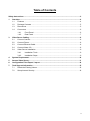
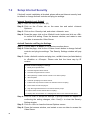
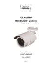
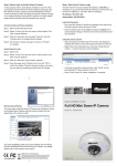
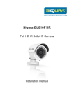
Video Server User’s Manual DN-16100-1 Ver1.0 Safety Instructions 1. Do not use the power supply with other voltages. The Video Server would be damaged if users use a power supply with different voltage than the one included with this device. All warranty of this product will be voided in the situation above. 2. Do not service this Video Server yourself. Opening or removing covers may expose you to dangerous voltage. 3. Do not use accessories and attachments which are not recommended by the manufacturer. 4. Do not use the Video Server near water or install this device and the power supply in the dry place. 2 Table of Contents Safety Instructions........................................................................................................................ 2 1 3 Overview ................................................................................................................................ 4 1.1 Features ...................................................................................................................... 4 1.2 Package Contents ....................................................................................................... 5 1.3 Dimensions .................................................................................................................. 5 1.4 Connectors .................................................................................................................. 6 1.4.1 Front Panel................................................................................................... 6 1.4.2 Rear Panel ................................................................................................... 7 Video Server Cabling ............................................................................................................ 8 3.1 Connect Camera ......................................................................................................... 8 3.2 Connect Power ............................................................................................................ 8 3.3 Connect Ethernet Cable............................................................................................... 8 3.4 Connect Alarm I/O ....................................................................................................... 8 3.4 Video Server Installation .............................................................................................. 9 3.4.1 Installation Tools .......................................................................................... 9 3.4.2 Installation Steps .......................................................................................... 9 4 System Requirement .......................................................................................................... 10 5 Access Video Server ........................................................................................................... 11 6. Configuration Files Export / Import ................................................................................... 14 7. Tech Support Information .................................................................................................. 15 7.1 Delete the Existing Viewer ......................................................................................... 15 7.2 Setup Internet Security .............................................................................................. 16 3 1 Overview This Video Server provides a stable platform for transitioning traditional analog CCTV cameras to IP-based system. With the ability to select H.264 or MJPEG video compression, the Video Server offers scalability and efficient use of network bandwidth. By combining the Video Server and DVR which can get IP from the internet, users can promote the analog cameras to become an IP-based surveillance system that reduces wiring cost and maximizes the convenience of distant surveillance application. 1.1 Features 4 Dual Streams, D1 + D1 @ 60fps Quad Stream Support H.264 Baseline / Main Profile / High Profile and MJPEG Codec support Alarm Input / Output BNC Input / Output Line In / Line Out RS-485 Support DC 12V Power Output Triple Power Support: PoE, DC 12V~ 48V and AC 24V Onvif Profile S Conformance 1.2 Package Contents Please check the package contains the following items listed below. Video Encoder DC Jack Cable (Length: 300mm) M4A Pan Head Self-tapping Screw 1.3 M4 Plastic Anchors (Length: 35mm) Quick Guide CD (bundled software and documentation) Dimensions The dimensions of the Video Server are shown below. 5 1.4 Connectors The definition for each connector on the Video Server is given as follows. 1.4.1 Front Panel The connectors on the front panel are illustrated and introduced as below. No. 1 2 3 4 5 6 Connector Power Out Line Out Line In BNC Output BNC Input Definition For DC12V power output Audio Out Audio In For analog video output For analog video input 1.4.2 Rear Panel The connectors on the rear panel are illustrated and introduced as below. No. Connector Pin 1 SD Card Slot - 2 3 RJ-45 Power In - 4 Default Button - RS-485 & Alarm I/O 1 2 3 4 5 6 7 5 Definition Remarks Insert the microSD card into the card slot to store videos and snapshots. Do not remove the microSD card when the Video Server is powered on. For network and PoE connections For DC12V~48V / AC 24V power input Press this button with a proper tool for at least 20 seconds to restore the system. D+ DRS-485 connection GND Alarm InAlarm In+ Alarm connection Alarm Out Alarm Out + NOTE: It is not recommended to record with the microSD card for 24/7 continuously, as it may not be able to support long term continuous data read/write. Please contact the manufacturer of the microSD card for information regarding the reliability and the life expectancy. 7 3 Video Server Cabling Before connecting cables, make sure that all cables and the power adaptor are placed in dry and well-waterproofed environments, e.g. waterproof boxes. The purpose is to prevent moisture accumulation inside the Video Server and moisture penetration into cables, which might lead to device breakdown. Please refer to the following sections for Video Server connection. 3.1 Connect Camera Connect an analog camera to the BNC connector of the Video Server. Please refer to section Connectors. 3.2 Connect Power Please refer to section Connectors. Alternatively, users can power up the Video Server by PoE if a Power Sourcing Equipment (PSE) switch is available. Refer to the next section for Ethernet cable connection. NOTE: If PoE is used, make sure the PSE switch is in used in the network. 3.3 Connect Ethernet Cable To have best transmission quality, cable length shall not exceed 100 meters. Connect one end of an Ethernet cable to the RJ-45 connector of the Video Server, and the other end of the cable to the network switch or PC. NOTE: In some cases, Ethernet crossover cable might be needed when connecting the Video Server directly to the PC. Check the status of the link indicator and activity indicator LEDs. If the LEDs are unlit, please check the LAN connection. AUTO IRIS DC12V RESET NETWORK LINE OUT Connect Alarm I/O VIDEO DC 1 2 3 4 LINE IN MIC IN 3.4 Green Link Light indicates good network connection. Orange Activity Light flashes for network activity indication. I/O The Video Server supports one alarm input and one relay output for alarm application. Refer to section Connectors for pin definitions. 8 3.4 Video Server Installation 3.4.1 Installation Tools Power Drill 3.4.2 M4 Phillips-head screwdriver Hammer Installation Steps STEP 1 Use a power drill to drill two holes on the ceiling or wall for the two M4 Plastic Anchors. STEP 2 Use a hammer to install two M4 Plastic Anchors into the holes. STEP 3 Install the Video Server to the ceiling. Tighten the two M4 Pan Head Self-tapping Screws into Plastic Anchors. 9 4 System Requirement To perform the Video Server via web browser, please ensure the PC is in good network connection, and meet the system requirements as described below. Items System Requirement 1. Intel® Pentium IV, 3 GHz or higher; Personal Computer Intel® CoreTM2 Duo, 2 GHz or higher 2. 1 GB RAM or more 3. AGP graphics card 64 MB RAM, DirectDraw Operating System Windows VISTA/ Windows XP/ Window 7 Microsoft Internet Explorer 6.0 or later Web Browser Firefox Chrome Safari 10 Network Card 10Base-T (10 Mbps) or 100Base-TX (100 Mbps) operation Viewer ActiveX control plug-in for Microsoft IE 5 Access Video Server For initial access to the Video Server, users can search through the installer program: DeviceSearch.exe, which can be found in “DeviceSearch” folder in the supplied CD. Accessing the Video Server by Device Search Software Step 1: Double click on the program Device Search.exe. Step 2: After its window appears, click on the <Device Search> button on the top. All found IP devices will be listed in the page. Step 3: Find the Video Server in the list by its IP address and click on it. The default IP address of the Video Server is: 192.168.0.250. Step 4: The default IP address of the Video Server may not be in the same LAN as the IP address of the PC. If so, the IP address of the Video Server needs to be changed. Right click on the Video Server and click <Network Setup>. Meanwhile, record the MAC address of the camera, for future identification. Step 5: The <Network Setup> page will come out. Select <DHCP> and click <Apply> down the page. The Video Server will be assigned with a new IP address. Step 6: Click <OK> on the Note of setting change. Wait for one minute to re-search the Video Server. Step 7: Click on the <Device Search> button to re-search all the devices. Find the Video Server in the list by its MAC address. Then double click or right click and select <Browse> to access the camera directly via a web browser. 11 Step 8: A prompt window requesting for default username and password will appear. Enter the default username and password shown below to login to the Video Server. Login ID Password admin admin NOTE: ID and password are case sensitive. NOTE: It is strongly advised that administrator’s password be altered for the security concerns. Refer to the Camera’s Web UI Manual in the supplied CD for further details. Installing Viewer Software Online For the initial access to the Video Server, a client program, Viewer, will be automatically installed to the PC when connecting to the Video Server. If the web browser does not allow Viewer installation, please check the Internet security settings or ActiveX controls and plug-ins settings (refer to section Setup Internet Security) to continue the process. The Information Bar (just below the URL bar) may come out and ask for permission to install the ActiveX Control for displaying video in browser. Right click on the Information Bar and select <Install ActiveX Control…> to allow the installation. The download procedure of Viewer software is specified as follows. Step 1: In the Viewer installation window, click on <Next> to start installation. Step 2: The status bar will show the installation progress. After the installation is completed, click on <Finish> to exit the installation process. Step 3: Click on <Finish> to close the Viewer installation page. 12 Once the Viewer is successfully installed, the Home page of the Video Server will be shown as the figure below. Users now can setup the configuration of the connected analog camera with this user-friendly browser-based interface. 13 6. Configuration Files Export / Import To export / import configuration files, users can access the Maintenance page on the user-friendly browser-based configuration interface. The Maintenance setting can be found under this path: System> Maintenance. Users can export configuration files to a specified location and retrieve data by uploading an existing configuration file to the camera. It is especially convenient to make multiple cameras having the same configuration. Export Users can save the system settings by exporting the configuration file (.bin) to a specified location for future use. Click on the <Export> button, and the popup File Download window will come out. Click on <Save> and specify a desired location for saving the configuration file. Upload To upload a configuration file to the camera, click on <Browse> to select the configuration file and then click on the <Upload> button for uploading. 14 7. Tech Support Information This chapter will introduce how to delete previously-installed Viewer in the PC and how to setup the Internet security. 7.1 Delete the Existing Viewer For users who have installed the Viewer in the PC previously, please remove the existing Viewer from the PC before accessing to the Video Server. Deleting the Viewer In the Windows <Start Menu>, activate <Control Panel>, and then double click on <Add or Remove Programs>. In the <Currently installed programs> list, select <Viewer> and click on the button <Remove> to uninstall the existing Viewer. Deleting Temporary Internet Files To improve browser performance, it is suggested to clean up all the files in the Temporary Internet Files. The procedure is as follows. Step 1: Click on the <Tools> tab on the menu bar and select <Internet Options>. Step 2: Click on the <Delete> button under the <Browsing History> section. Step 3: In the appeared window, tick the box beside the <Temporary Internet Files> and click on <Delete> to start deleting the files. 15 7.2 Setup Internet Security If ActiveX control installation is blocked, please either set Internet security level to default or change ActiveX controls and plug-ins settings. Internet Security Level: Default Step 1: Start the Internet Explorer (IE). Step 2: Click on the <Tools> tab on the menu bar and select <Internet Options>. Step 3: Click on the <Security> tab, and select <Internet> zone. Step 4: Down the page, click on the <Default Level> button and click on <OK> to confirm the setting. Close the browser window, and restart a new one later to access the Video Server. ActiveX Controls and Plug-ins Settings Step 1: Repeat Step 1 to Step 3 of the previous section above. Step 2: Down the page, click on the <Custom Level> button to change ActiveX controls and plug-ins settings. The Security Settings window will pop up. Step 3: Under <ActiveX controls and plug-ins>, set ALL items (as listed below) to <Enable> or <Prompt>. Please note that the items vary by IE version. ActiveX controls and plug-ins settings: 1. Binary and script behaviors. 2. Download signed ActiveX controls. 3. Download unsigned ActiveX controls. 4. Allow previously unused ActiveX controls to run without prompt. 5. Allow Scriptlets. 6. Automatic prompting for ActiveX controls. 7. Initialize and script ActiveX controls not marked as safe for scripting. 8. Run ActiveX controls and plug-ins. 9. Only allow approved domains to use ActiveX without prompt. 10. Script ActiveX controls marked safe for scripting*. 11. Display video and animation on a webpage that does not use external media player. Step 4: Click on <OK> to accept the settings. A prompt window will appear for confirming the setting changes, click <Yes(Y)> to close the Security Setting window. Step 5: Click on <OK> to close the Internet Options screen. Step 6: Close the browser window, and restart a new one later to access the Video Server. 16