1
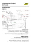
Siemens
Energy & Automation
INSTALLATION AND SERVICE INSTRUCTION
SD61H-1
Rev 8
May 2009
Supersedes Rev 7
Model 61H F/R Booster Relay
INTRODUCTION
Designed to meet high-speed control applications, the Model 61H F/R Booster Relay
produces a high volume boosting action. Its primary purpose is for use with valve
positioners, although it can be used by itself for the high volume of air it can control.
(This relay is not normally used in measuring circuits.)
The relay contains an integral stabilizing bypass valve, eliminating the need for an
externally piped bypass. The bypass opening is controlled by a screwdriver adjustment
in the body of the relay which permits tuning for optimal dynamic response. Opening
this valve improves the stability of the positioner/relay/actuator circuit.
This instruction has five major sections: Introduction, Installation, Maintenance, Warranty, and Parts List.
Specifications
Supply Pressure ......................................... 100 psig max.
Input Pressure ............................................ 100 psig max.
Accuracy of 1:1 Ratio................................ 5% (based on 3-15 psi input)
Reproducibility .......................................... 0.1% (based on 3-15 psi input)
Linearity .................................................... 0.4% (based on 3-15 psi input)
Maximum Flow Coefficient [Cv]............... 0.9 Supply; 1.1 Exhaust
Ambient Temperature Limits .................... -40° to +180°F (-40° to +82.2°C)
Materials of Construction .......................... Delrin™, aluminum, brass, stainless steel, Buna-N, epoxy polyester
powder coat, nickel plate; diaphragm material: nitrile on polyester
(effective mid-2009), neoprene on cotton/polyester
INSTALLATION
Shipping and Storage
If the relay is to be stocked, stored, or shipped to another location prior to piping, make sure that the factory
installed plastic plugs are in the ports to prevent entry of moisture, dirt, or other contaminants.
Mounting
Refer to relay installation drawing 10342-78 for mounting dimensions and location of input, output, and supply
ports. Relay input is often connected to the output of a positioner. Connections are 1/4" NPT. Mount the relay in a
reasonably vibration free location.
Operating temperature limits are listed in the Specifications section of this Instruction. The temperature in the
selected location must not exceed the specified operating temperatures.
CAUTION
Exceeding the specified ambient temperature limits can adversely affect
performance and may cause damage to the relay.
1
SD61H-1
Installation Drawing
2
SD61H-1
Blow out all piping before connections are made to prevent the possibility of dirt or chips entering the relay. Use
pipe sealant sparingly, and then only on the male threads. A non-hardening sealant is strongly recommended.
Connect the relay to a source of clean, dry, oil-free instrument air. See Instrument Air Requirements below.
CAUTION
Pressure in excess of 100 psi to any connection may cause damage to the relay. In
any event, maximum actuator pressure should never be exceeded.
Instrument Air Requirements
Connect the relay to a source of clean, dry, oil-free instrument air. Failure to do so will increase the possibility of a
malfunction or a deviation from specified performance.
CAUTION
Use of process fluids other than instrument air is not recommended. No claim is made as to
the suitability of this product for use with other process fluids, such as hazardous gases,
except as listed on the appropriate certificate. Non-approved instruments are suitable for
use with instrument air only. Optional features and modifications such as tapped exhaust do
not imply suitability for use with hazardous gases except as listed on the approval
certificate.
CAUTION
Synthetic compressor lubricants in the air system at the instrument may cause the
instrument to fail.
There are many types of synthetic compressor lubricants. Some may not be compatible with materials used in
construction of the relay. Wetting of these materials with such an oil mist or oil vapor, etc., may cause them to
deteriorate and may ultimately result in the failure of the instrument. The following materials are in contact with the
supply air: aluminum, brass, neoprene, buna-N and stainless steel.
The requirements for a quality air supply can be found in the Instrument Society of America’s “Quality Standard for
Instrument Air” (ISA-S7.3). Basically this standard calls for the following:
Particle Size – The particle size in the air stream at the instrument shall be no larger than 3 microns.
Dew Point – The dew point, at line pressure, should be at least 10°C (18°F) below the minimum temperature to
which any part of the instrument air system is exposed at any season of the year. Under no circumstances should
the dew point, at line pressure, exceed 2°C (35.6°F).
Oil Content – The maximum total oil or hydrocarbon content, exclusive of non-condensable, should not exceed 1
ppm under normal operating conditions.
MAINTENANCE
No lubrication of any sort is needed. The Parts List has spare and replacement part numbers.
CAUTION
Before disassembling the instrument, remove air pressure to the instrument.
When disassembling the instrument, make sure all parts are clean and free of dirt and debris. Reassembly is the
reverse order of disassembly. Make sure not to damage the O-ring(s) and diaphragm(s) when reassembling the
instrument.
3
SD61H-1
Parts Replacement
Refer to the Parts List at the back of this instruction when performing maintenance on the relay. It provides a list of
replacement parts and a cut-away view of the instrument.
Customer/Product Support
Support is available through an online Support Request service; a link is provided in
the table at the end of this section.
When contacting Siemens for support:
•
•
Please provide complete product information:
•
For hardware, this information is provided on the product nameplate
(part number or model number, serial number, and/or version).
•
For most software, this information is given in the Help > About screen.
If there is a problem with product operation:
•
Is the problem intermittent or repeatable? What symptoms have been observed?
•
What steps, configuration changes, loop modifications, etc. were performed before the problem
occurred?
•
What status messages, error messages, or LED indications are displayed?
•
What troubleshooting steps have been performed?
•
Is the installation environment (e.g. temperature, humidity) within the product’s specified operating
parameters? For software, does the PC meet or exceed the minimum requirements (e.g. processor,
memory, operating system)?
•
A copy of the product Service Instruction, User’s Manual, or other technical publication should be at hand. The
Siemens public Internet site (see the table) has current revisions of technical literature, in Portable Document
Format, for downloading.
•
To send an instrument to Siemens for warranty or non-warranty service, call Repair Service and request a
Return Material Authorization (RMA).
IMPORTANT
An instrument must be thoroughly cleaned (decontaminated) to remove any process materials,
hazardous materials, or blood-borne pathogens prior to return for repair. Read and complete the
Siemens RMA form(s).
For the location of your local Siemens representative, visit the Siemens Process Instrumentation product support
page at http://www2.sea.siemens.com/Products/Process-Instrumentation/Support/Customer-Support.htm.
For technical support refer to the following table and click the appropriate link.
Technical Support
Online Support Request
Telephone
Hours of Operation
Technical Publications
in PDF
Public Internet Site
Repair Service
http://www.siemens.com/automation/support-request
1 800 333 7421
8 a.m. to 5:00 p.m. eastern time, Monday through Friday (except holidays)
http://www2.sea.siemens.com/Products/Process-Instrumentation/Support/PI-UserManuals.htm then click the product line (e.g. Control Solutions)
http://www2.sea.siemens.com/Products/Process-Instrumentation
1 800 365 8766 extension 4519 (for warranty and non-warranty service)
4
SD61H-1
WARRANTY
(a) Seller warrants that on the date of shipment the goods are of the kind and quality described herein and
are free of non-conformities in workmanship and material. This warranty does not apply to goods
delivered by Seller but manufactured by others.
(b) Buyer's exclusive remedy for a nonconformity in any item of the goods shall be the repair or the
replacement (at Seller's option) of the item and any affected part of the goods. Seller’s obligation to repair
or replace shall be in effect for a period of one (1) year from initial operation of the goods but not more
than eighteen (18) months from Seller’s shipment of the goods, provided Buyer has sent written notice
within that period of time to Seller that the goods do not conform to the above warranty. Repaired and
replacement parts shall be warranted for the remainder of the original period of notification set forth above,
but in no event less than 12 months from repair or replacement. At its expense, Buyer shall remove and
ship to Seller any such nonconforming items and shall reinstall the repaired or replaced parts. Buyer shall
grant Seller access to the goods at all reasonable times in order for Seller to determine any nonconformity
in the goods. Seller shall have the right of disposal of items replaced by it. If Seller is unable or unwilling
to repair or replace, or if repair or replacement does not remedy the nonconformity, Seller and Buyer shall
negotiate an equitable adjustment in the contract price, which may include a full refund of the contract
price for the nonconforming goods.
(c) SELLER HEREBY DISCLAIMS ALL OTHER WARRANTIES, EXPRESS OR IMPLIED, EXCEPT
THAT OF TITLE. SPECIFICALLY, IT DISCLAIMS THE IMPLIED WARRANTIES OF
MERCHANTABILITY, FITNESS FOR A PARTICULAR PURPOSE, COURSE OF DEALING AND
USAGE OF TRADE.
(d) Buyer and successors of Buyer are limited to the remedies specified in this article and shall have no
others for a nonconformity in the goods. Buyer agrees that these remedies provide Buyer and its successors
with a minimum adequate remedy and are their exclusive remedies, whether Buyer's or its successors’
remedies are based on contract, warranty, tort (including negligence), strict liability, indemnity, or any
other legal theory, and whether arising out of warranties, representations, instructions, installations, or nonconformities from any cause.
(e) Note: The above does not apply to any software which may be furnished by Seller. In such cases, the
attached Software License Addendum applies.
For warranty and non-warranty service, refer to Customer/Product Support in this publication.
All product designations may be trademarks or product names of Siemens Energy & Automation, Inc. or other supplier
companies whose use by third parties for their own purposes could violate the rights of the owners. Delrin is a registered
trademark of E. I. du Pont de Nemours and Company.
Siemens Energy & Automation, Inc. assumes no liability for errors or omissions in this document or for the application and use
of information in this document. The information herein is subject to change without notice.
Procedures in this document have been reviewed for compliance with applicable approval agency requirements and are
considered sound practice. Neither Siemens Energy & Automation, Inc. nor these agencies are responsible for product uses not
included in the approval certification(s) or for repairs or modifications made by the user.
5
SD61H-1
PARTS LIST
Siemens Model 61H F/R Booster Relay
Drawing 10342PL
Rev 5/09 Supersedes 2/08
Item
1
4
5*
6
7
8
9*
10*
12*
13*
15
16
Part No.
10342-148
8377-76
TGX:10342270 or
10342-85
10342-147
10342-27
10342-25
2938-21
10342-11
TGX:10342272 or
10342-88
TGX:837780
10342-26
17
TGX:2881114
1145-19
A
1-3448
B
C
1-7303
1-1192
D
1-3465
Description
Top Housing
Exhaust Ring
Diaphragm
Assembly
Req’d
1
1
1
Bottom Housing
Pilot Screen
Retaining Screw
O-ring
Restriction Screw
Diaphragm
1
1
1
1
1
1
Plunger
1
Compression
Spring
Plunger Spring
1
1
Mounting Bracket,
Optional – Not
Shown
----
1/4-20 x 1-1/8 Lg.
Fill. Hd. Screw
1/4 Lockwasher
6-32 x 1/4 Lg.
Truss Hd. Screw
1/4-20 x 1-1/4 Lg.
Fill. Hd. Screw, For
Mounting Bracket Not Shown
6
6
1
----
* Recommended on-hand spare parts. Always specify
range, serial number, and other nameplate
information when ordering.
Items 5 and 12: TGX:10342-27_ replacement
diaphragms effective June 2009.
IMPORTANT
Service Parts Kits are available for servicing the
instrument. Contact Siemens for available kits; refer to
the Customer/Product Support section of this
instruction. Some parts in this Parts List may not be
available for separate purchase.
6