1
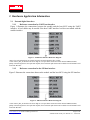
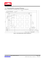
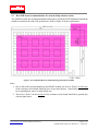
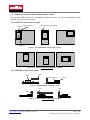
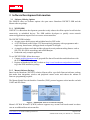
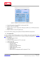
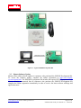
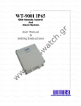
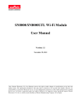
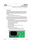
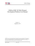
SN820X Wi-Fi Network Controller
Module Family
User Manual
Version: 2.2
March 3, 2014
Note: Murata Electronics N.A, Inc (Murata) reserves the right to make changes in specifications at any time and without
notice. The information furnished in this data sheet is believed to be accurate and reliable. However, no responsibility is
assumed by Murata for its use, nor any infringements of patents or other rights of third parties resulting from its use. No
license is generated under any rights of Murata or its supporters unless specifically agreed. Murata Electronics N.A, Inc
is a wholly owned subsidiary of Murata Manufacturing Company, Ltd. Of Japan.
Revision History
Revision
1.0
Date
09/30/13
Author
R. Willett
1.1
11/6/2013
R. Willett
2.0
11-26-2013
R. Willett
Removed references to SyChip; updated copyright, deleted Chap
11, “Disclaimer;”
2.1
12-17-13
R. Willett
Modified text regarding Module Software Downloading in section
4, page 13.
2.2
03-03-14
R. Willett
Revised text for Figures 1 and 2, page 6.
www.murata-ws.com E-mail: modules@ murata.com
©2014 by Murata
Change Description
Initial version
Revised Table 1; added Acronyms and References on page
5; revised Figures 1 and 2; revised Figure 11
Page 2 of 18
SN820X Module Family User Manual v2.1 – 03/03/2104
Table of Contents
1
INTRODUCTION .................................................................................................................................................... 5
1.1
1.2
1.3
2
SN820X WI-FI NETWORK CONTROLLER MODULE FAMILY ................................................................................... 5
ACRONYMS............................................................................................................................................................. 5
REFERENCES........................................................................................................................................................... 5
HARDWARE APPLICATION INFORMATION................................................................................................. 6
2.1 EXTERNAL DIGITAL INTERFACES ............................................................................................................................ 6
2.1.1
Reference connection for UART host interface ............................................................................................ 6
2.1.2
Reference connection for the SPI host interface .......................................................................................... 6
2.2 RECOMMENDED HOST (CUSTOMER) PCB PATTERN................................................................................................. 7
2.3 HOST PCB LAYOUT RECOMMENDATIONS FOR ON-BOARD CHIP ANTENNA VERSION ............................................... 8
2.4 MODULE LOCATION FOR ON-BOARD CHIP ANTENNA VERSION ................................................................................ 9
2.4.1
SN820X Location in the x-y plane ................................................................................................................ 9
2.4.2
SN820X Location in the z-plane ................................................................................................................... 9
3
SOFTWARE DEVELOPMENT INFORMATION............................................................................................. 10
3.1 SOFTWARE OFFERING OPTIONS ............................................................................................................................ 10
3.1.1
WICED SDK............................................................................................................................................... 10
3.1.2
Murata Software Package .......................................................................................................................... 10
3.2 DEVELOPMENT KIT .............................................................................................................................................. 11
3.3 MURATA SOFTWARE UPDATE .............................................................................................................................. 12
4
MODULE SOFTWARE DOWNLOADING........................................................................................................ 13
5
ASSEMBLY INFORMATION ............................................................................................................................. 14
5.1
6
REGULATORY INFORMATION ....................................................................................................................... 15
6.1
6.2
6.3
6.4
6.5
6.6
6.7
6.8
7
LEAD-FREE SOLDERING REFLOW PROFILE ............................................................................................................. 14
FCC NOTICE (USA) ............................................................................................................................................. 15
FCC LABELING REQUIREMENTS........................................................................................................................... 15
RF EXPOSURE....................................................................................................................................................... 16
FCC NOTICES ....................................................................................................................................................... 16
IC NOTICE (CANADA)........................................................................................................................................... 16
IC LABELING REQUIREMENTS .............................................................................................................................. 17
CE NOTICE (EUROPE) ........................................................................................................................................... 17
CE LABELING REQUIREMENTS ............................................................................................................................. 17
TECHNICAL SUPPORT CONTACT ................................................................................................................. 18
www.murata-ws.com E-mail: modules@ murata.com
©2014 by Murata
Page 3 of 18
SN820X Module Family User Manual v2.1 – 03/03/2104
LIST OF FIGURES
FIGURE 1 - UART HOST INTERFACE REFERENCE DIAGRAM ................................................................................................. 6
FIGURE 2 - SPI HOST INTERFACE REFERENCE DIAGRAM ...................................................................................................... 6
FIGURE 3 - RECOMMENDED HOST (CUSTOMER) PCB PATTERN ............................................................................................ 7
FIGURE 4 - RECOMMENDED HOST CIRCUIT BOARD DESIGN BENEATH THE SN820X ............................................................ 8
FIGURE 5 - RECOMMENDED LOCATIONS IN THE XY-PLANE ................................................................................................... 9
FIGURE 6 - LOCATIONS NOT RECOMMENDED IN THE XY-PLANE ........................................................................................... 9
FIGURE 7 - RECOMMENDED LOCATIONS IN Z PLANE ............................................................................................................ 9
FIGURE 8 - LOCATIONS NOT RECOMMENDED IN XY-PLANE .................................................................................................. 9
FIGURE 9 - SN820X SNIC SOFTWARE ARCHITECTURE DIAGRAM ..................................................................................... 10
FIGURE 10 - SN820X EZ WEB WIZZARD SOFTWARE ARCHITECTURE DIAGRAM ............................................................... 11
FIGURE 11 - TYPICAL SN8200 DEVELOPMENT KIT ............................................................................................................. 12
FIGURE 12 - REFLOW PROFILE PATTERN............................................................................................................................. 14
LIST OF TABLES
TABLE 1 - SN820X WI-FI NETWORK CONTROLLER MODULE FAMILY CONFIGURATION COMPARISON ............................... 5
TABLE 2 - REFLOW PROFILE RECOMMENDATION ............................................................................................................... 14
www.murata-ws.com E-mail: modules@ murata.com
©2014 by Murata
Page 4 of 18
SN820X Module Family User Manual v2.1 – 03/03/2104
1 Introduction
This user manual addresses the topics that are important for employing the SN820X Module in
design, software development, regulatory certification and device manufacturing.
1.1 SN820X Wi-Fi Network Controller Module Family
The SN820X Module Family is a portfolio of low power, self-contained, embedded wireless module
solutions that address the connectivity demands of M2M applications. These products integrate a
micro-controller, a Wi-Fi BB/MAC/RF IC, an RF front end and two clocks into small form factor
modules. The module family includes 2 different micro-controller options as shown below. The
modules can also be purchased with either a standard on-board chip antenna or a U.FL connector
where remote antenna flexibility is required.
Model #
P/N
Built-in STM
RAM Size
Flash Size
SN8200
88-00151-00
ARM Cortex M3
96KB
768KB
SN8200UFL
88-00151-02
ARM Cortex M3
96KB
768KB
SN8205
88-00158-00
ARM Cortex M3
128KB
1024KB
SN8205UFL
88-00158-02
ARM Cortex M3
128KB
1024KB
Table 1 - SN820X Wi-Fi Network Controller Module Family Configuration Comparison
1.2
Acronyms
ADC
Analog to Digital Converter
DAC
Digital to Analog Converter
GPIO
General-Purpose Input-Output
I2C
Intelligent Interface Controller
I2S
Integrated Interchip Sound
ISM
Industrial, Scientific and Medical
MAC
Medium Access Control
MSL
Moisture Sensitivity Level
PER
Packet Error Rate
ROHS
Restriction of Hazardous Substances
SPI
Serial Peripheral Interface
UART
Universal Asynchronous Receiver-Transmitter
1.3
[1]
[2]
[3]
[4]
References
STM32F103RF Data Sheet, ST Microelectronics
STM32F205RG Data Sheet, ST Microelectronics
SN820X Wi-Fi Network Controller Module Family Data Sheet, Murata
AN_SN8200_002 SN820X Firmware Downloading Application Note, Murata
www.murata-ws.com E-mail: modules@ murata.com
©2014 by Murata
Page 5 of 18
SN820X Module Family User Manual v2.1 – 03/03/2104
2 Hardware Application Information
2.1
External digital interfaces
2.1.1
Reference connection for UART host interface
Figure 1 illustrates the connections between the module and the host MCU using the UART
interface. A level shifter may be needed if the host UART interface level does not match with the
module interface.
Figure 1 - UART Host Interface Reference Diagram
*Note: The CTS and RTS pins are optional and only needed for hardware flow control.
**Note: Micro_RST_N should not be driven high. It is an open-drain connection with an internal 40KΩ (nominal)
pullup. If the driving GPIO is not open-drain capable, then a transistor pull-down must be added. The internal Micro will
control the RST line.
2.1.2
Reference connection for the SPI host interface
Figure 2 illustrates the connections between the module and the host MCU using the SPI interface.
Figure 2 - SPI Host Interface Reference Diagram
**Note: Micro_RST_N should not be driven high. It is an open-drain connection with an internal 40KΩ (nominal)
pullup. If the driving GPIO is not open-drain capable, then a transistor pull-down must be added. The internal Micro will
control the RST line.
www.murata-ws.com E-mail: modules@ murata.com
©2014 by Murata
Page 6 of 18
SN820X Module Family User Manual v2.1 – 03/03/2104
2.2 Recommended host (customer) PCB pattern
Figure 3 illustrates the recommended host circuit board land pattern.
Figure 3 - Recommended Host (customer) PCB Pattern
www.murata-ws.com E-mail: modules@ murata.com
©2014 by Murata
Page 7 of 18
SN820X Module Family User Manual v2.1 – 03/03/2104
2.3 Host PCB layout recommendations for on-board chip antenna version
The SN820X module has an onboard antenna and requires careful host PCB alignment beneath the
module to maximize the radio’s RF performance. Refer to Figure 4 for the requirements.
Figure 4 - Recommended Host Circuit Board Design beneath the SN820X
Notes:
1. Due to the surface mount antenna on the SN820X module, the area in ‘Zone1’ on all layers
of the customer circuit board should be free of any metal objects. Specifically, there should
be no ground plane, traces or metal shield case.
2. The area in ‘Zone2’ on the top layer of the customer circuit board should have ground only
with no signal traces.
www.murata-ws.com E-mail: modules@ murata.com
©2014 by Murata
Page 8 of 18
SN820X Module Family User Manual v2.1 – 03/03/2104
2.4 Module Location for on-board chip antenna version
For optimum EIRP (Effectively Isotropically Radiated Power), use the recommended module
location on your host circuit board.
2.4.1 SN820X Location in the x-y plane
Antenna Connector
No GND in this area (See Fig.8)
Antenna
Shield Case
Figure 5 - Recommended Locations in the xy-plane
Figure 6 - Locations Not Recommended in the xy-plane
2.4.2 SN820X Location in the z-plane
Metal
Module
Antenna Connector
Antenna
Mother Board
Metal
Figure 7 - Recommended Locations In z Plane
Metal
Metal
Metal
Figure 8 - Locations Not Recommended in xy-plane
www.murata-ws.com E-mail: modules@ murata.com
©2014 by Murata
Page 9 of 18
SN820X Module Family User Manual v2.1 – 03/03/2104
3 Software Development Information
3.1 Software Offering Options
The SN820X offers two software options: the open source Broadcom WICED™ SDK and the
Murata software package.
3.1.1 WICED SDK
WICED™ is a Broadcom development system that vastly reduces the effort required to add wireless
connectivity to embedded devices. The SDK enables developers to quickly create network
connected applications targeted for low-resource microcontrollers.
The WICED™ SDK includes:
• An open source build system and toolchain based on GNU make.
• A GUI IDE based on the Eclipse CDT that seamlessly integrates with a programmer and a
single-step, thread-aware, debugger based on OpenOCD and gdb.
• A complete software stack that includes advanced security and networking features such as
SSL/TLS, IPv4/IPv6 networking, and mDNS/Bonjour.
• Production ready example applications.
To use WICED™ SDK, follow these steps:
1. Contact [email protected] to get patch files that will match the module hardware with
the WICED™ SDK, and
2. Register at Broadcom WICED™ website at: http://www.broadcom.com/products/wiced/wifi/
to get the SDK installation package
3.1.2 Murata Software Package
Based on the Broadcom WICED™ solution, Murata offers a pre-built firmware/software package
that makes host integration, wireless and peripheral control easier and reduces the amount of
firmware programming required.
The Murata Simple Network Interface Controller (SNIC) protocol supports socket interface on both
UART and SPI to host.
Module
Figure 9 - SN820X SNIC Software Architecture Diagram
Murata’s EZ Web Wizzard™ (EWW) software supports easy, custom web-based control to reduce
cost on an additional host microcontroller.
www.murata-ws.com E-mail: modules@ murata.com
©2014 by Murata
Page 10 of 18
SN820X Module Family User Manual v2.1 – 03/03/2104
Figure 10 - SN820X EZ Web Wizzard Software Architecture Diagram
•
•
•
•
Controls I/O interfaces through HTML, JavaScript and JSON
Supports UART, I2C and GPIOs
Supports wireless network configuration, JSON parser, HTTP server, TCP/IP network stack,
and WiFi driver
Enables creation of wireless IP-capable nodes
To access the software package, please purchase the Murata SN820X Development Kit.
3.2 Development Kit
To allow evaluation of the SN820x module as well as to facilitate and expedite application software
development, Murata offers the SN820X Wi-Fi Network Controller Development Kit + (see figure
11). The kit includes:
• An SN820X Evaluation Board
• A mini USB cable
• A reference external antenna (for U.FL version only)
• A Quick Start Guide
• A CD containing the following:
o EVK User Guide
o Software User Guide
o Software Interface Specification
o Sample Source Code
o Sample Application User Guide
o USB PC Drivers
o Murata Software Configuration and Development PC Tool
www.murata-ws.com E-mail: modules@ murata.com
©2014 by Murata
Page 11 of 18
SN820X Module Family User Manual v2.1 – 03/03/2104
Figure 11 - Typical SN8200 Development Kit
3.3 Murata Software Update
Murata offers online software updates to customers who purchased the SN820X Development Kit.
To access the software update, complete the online registration at http://www.murataws.com/register.htm. The SN820X Development Kit includes the required EVK Registration Code.
Murata strongly recommends that all customers who purchase the SN820X Development Kit
complete the online registration immediately in order to receive the latest software offerings and
application notes.
www.murata-ws.com E-mail: modules@ murata.com
©2014 by Murata
Page 12 of 18
SN820X Module Family User Manual v2.1 – 03/03/2104
4 Module Software Downloading
Because no single firmware can meet the requirements of all customers, Murata has several options
that make the SN820X module family adaptable to many applications. The modules are delivered
with no application firmware pre-installed.
Finalize the firmware image, and then download the firmware to the module. For more details,
please see page 5, reference [4] AN_SN8200_002 SN820X Firmware Downloading Application
Note, Murata,.
.
www.murata-ws.com E-mail: modules@ murata.com
©2014 by Murata
Page 13 of 18
SN820X Module Family User Manual v2.1 – 03/03/2104
5 Assembly Information
5.1 Lead-free soldering reflow profile
When attaching the SN820X module to its host PCB, use the recommended lead-free soldering
reflow profile shown in the table & graph below.
The module is designed to withstand two reflows. Opposite side reflow is prohibited due to the
weight of the module.
Table 2 - Reflow Profile Recommendation
3o C/second max
120 seconds
250o C
20 seconds
6o C/second max
Ramp up rate
Maximum time maintained above 217o C
Peak temperature
Maximum time within 5o C of peak temperature
Ramp down rate
Reflow Profile
Temperature, C
250
200
150
100
50
0
Time, seconds
Figure 12 - Reflow Profile Pattern
www.murata-ws.com E-mail: modules@ murata.com
©2014 by Murata
Page 14 of 18
SN820X Module Family User Manual v2.1 – 03/03/2104
6 Regulatory Information
The SN820X module family has obtained the certifications described below. The antennas listed in
the table below are approved for use with the UFL versions.
Part Number
Vendor
TRF-1002
W1049B050
Microchip
Pulse
Gain
(dBi)
5.0
2.0
Type
Connector
Remarks
Omnidirectional
Omnidirectional
U.FL
U.FL
For FCC/IC compliance
For FCC/IC and ETSI compliance
6.1 FCC Notice (USA)
This device complies with Part 15 of the FCC rules. Operation is subject to the following two
conditions: (1) this device may not cause harmful interference, and (2) this device must accept any
interference received, including interference that may cause undesired operation.
The FCC requires the OEM to be notified of any changes or modifications. Changes or
modifications not expressly approved by Murata could void the user’s authority to operate the
equipment. While an application of the SN820X module in a product is not required to obtain a new
FCC authorization for the module, this does not preclude the possibility that some other form of
authorization or testing may be required for that end product.
This device, using the integrated antenna, has been tested to comply with FCC CFR Part 15. The
device meets the requirements for modular transmitter approval as detailed in the FCC public notice
DA00.1407.
This equipment has been tested and found to comply with the limits for a Class B digital device,
pursuant to Part 15 of the FCC Rules. These limits are designed to provide reasonable protection
against harmful interference in a residential installation. This equipment generates, uses and can
radiate radio frequency energy and, if not installed and used in accordance with the instructions, may
cause harmful interference to radio communications. However, there is no guarantee that
interference will not occur in a particular installation. If this equipment does cause harmful
interference to radio or television reception, which can be determined by turning the equipment off
and on, the user is encouraged to try to correct the interference by one or more of the following
measures: reorient or relocate the receiving antenna, increase the separation between the equipment
and receiver, connect the equipment into an outlet on a circuit different from that to which the
receiver is connected, or consult the dealer or an experienced radio/TV technician for help.
6.2 FCC Labeling Requirements
When integrating the SN820X into a product, the FCC labeling requirements must be met. This
includes a clearly visible label on the outside of the finished product specifying the SN820X FCC
identifier (FCC ID: QPU8200) as well as the notice above. The exterior label can use wording such
as “Contains Transmitter Module FCC ID: QPU8200” or “Contains FCC ID: QPU8200” although
any similar wording that expresses the same meaning may be used.
www.murata-ws.com E-mail: modules@ murata.com
©2014 by Murata
Page 15 of 18
SN820X Module Family User Manual v2.1 – 03/03/2104
6.3 RF Exposure
This module has been certified for remote and base radio applications and is not intended to be
operated within 20 cm of the body. If the module will be used for portable applications, the device
must undergo SAR testing.
The following statement must be included as a CAUTION statement in manuals for the products to
alert users on FCC RF exposure compliance:
“WARNING: To satisfy FCC RF exposure requirements for mobile transmitting devices, a
separation distance of 20cm or more should be maintained between the antenna of this device and
persons during operation. To ensure compliance, operations at closer distances than this are not
recommended.”
6.4 FCC Notices
IMPORTANT: The SN820X Wi-Fi Module has been certified by the FCC for use with other
products without any further certification (as per FCC section 2.1091). Modifications not expressly
approved RFM could void the user's authority to operate the equipment.
IMPORTANT: OEMs must test final product to comply with unintentional radiators (FCC section
15.107 &15.109) before declaring compliance of their final product to Part 15 of the FCC Rules.
6.5 IC Notice (Canada)
The term “IC” before the certification/registration number only signifies that the Industry Canada
technical specifications were met.
Le terme “IC” devant le numéro de certification /d’enregistrement signifie seulement que les
spécifications techniques Industrie Canada ont été respectées.
This device complies with Industry Canada license-exempt RSS standard(s). Operation is subject to
The following two conditions: (1) this device may not cause interference, and (2) this device must
accept any interference, including interference that may cause undesired operation of the device.
Cet appareil est conforme avec Industrie Canada RSS standard exempts de licence (s). Son
utilisation est soumise à Les deux conditions suivantes: (1) cet appareil ne peut pas provoquer
d'interférences et (2) cet appareil doit accepter Toute interférence, y compris les interférences qui
peuvent causer un mauvais fonctionnement du dispositif.
This device complies with Health Canada’s Safety Code 6 / IC RSS-210. The installer of this device
should ensure that RF radiation is not emitted in excess of the Health Canada’s requirement.
Information can be obtained at: http://www.hc-sc.gc.ca/ewh-semt/pubs/radiation/radio_guidelignes_direct-eng.php
www.murata-ws.com E-mail: modules@ murata.com
©2014 by Murata
Page 16 of 18
SN820X Module Family User Manual v2.1 – 03/03/2104
Cet appareil est conforme avec Santé Canada Code de sécurité 6 / IC RSS-210. Le programme
d'installation de cet appareil doit s'assurer que les rayonnements RF n'est pas émis au-delà de
l'exigence de Santé Canada. Les informations peuvent être obtenues: http://www.hc-sc.gc.ca/ewhsemt/pubs/radiation/radio_guide-lignes_direct-eng.php
6.6 IC Labeling Requirements
The host device should be properly labeled to identify the module within the host device. The
Industry Canada certification label of a module shall be clearly visible at all times when installed in
the host device, otherwise the host device must be labeled to display the Industry Canada
certification number of the module, preceded by the words “Contains transmitter module”, or the
word “Contains”, or similar wording expressing the same meaning, as follows:
Contains transmitter module IC: 4523A-SN8200, where 4523A-SN8200 is the module’s
certification number.
6.7 CE Notice (Europe)
This device has been tested and certified for use in the European Union.
If this device is used in a product, the OEM has the responsibility to verify compliance of the final
product to the EU standards. A Declaration of Conformity must be issued and kept on file as
described in Annex II of the Radio and Telecommunications Terminal Equipment Directive.
6.8 CE Labeling Requirements
The ‘CE’ mark must be placed on the OEM product per the labeling requirements of the Directive.
Given that the operating frequency band is not harmonized by a few European countries, the
restriction or alert sign must be placed alongside the ‘CE’ mark as shown below. As of the date of
this document, only France has a restriction. The restriction is that, if the radio is operated outdoors
in the 2450-2483.5 MHz band, the power must be limited to 10 mW instead of 100 mW. The OEM
must account for this and the product must have the alert mark. It does not require country
notifications, however.
www.murata-ws.com E-mail: modules@ murata.com
©2014 by Murata
Page 17 of 18
SN820X Module Family User Manual v2.1 – 03/03/2104
7 Technical Support Contact
For technical support, contact [email protected].
Murata Electronics, N.A., Inc.
4441 Sigma Road
Dallas, TX 75244
USA
www.murata-ws.com E-mail: modules@ murata.com
©2014 by Murata
Page 18 of 18
SN820X Module Family User Manual v2.1 – 03/03/2104