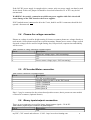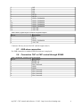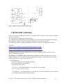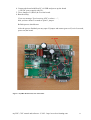
1
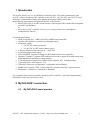
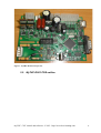
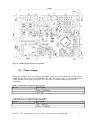
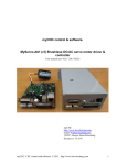
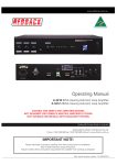
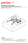
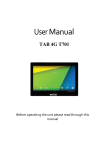
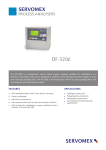
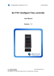
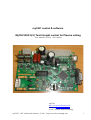
myCNC control & software.
MyTHC-RU01(r2) Torch Height control for Plasma cutting
User manual (rev 0.03 - 2012-0424)
myCNC
http://www.bevelcutting.com
email: [email protected]
195257, Russia, Saint-Petersburg
myCNC, CNC control and software. © 2011. http://www.bevelcutting.com
1
Severny st. 73-1-91
myCNC, CNC control and software. © 2011. http://www.bevelcutting.com
2
Using This Manual
This user manual provides information for proper installation of the myTHC-RU01 Torch height
controller.
WARNING: Machinery in motion can be dangerous! It is the responsibility of the user to design
effective error handling and safety protection as part of the machinery. myCNC shall not be
liable or responsible for any incidental or consequential damages.
Table of content
1 Introduction...................................................................................................................................5
2 MyTHC-RU01 connection...........................................................................................................5
2.1. MyTHC-RU01 board preview..............................................................................................5
2.2. MyTHC-RU01 PCB outline.................................................................................................6
2.3. Power supply.........................................................................................................................7
2.4. Plasma Arc voltage connection.............................................................................................8
2.5. DC brushed Motor connection..............................................................................................8
2.6. Binary inputs/outputs connection.........................................................................................8
2.7. USB-slave connection...........................................................................................................9
2.8. Connection THC to CNC control through RS485................................................................9
3 MyTHC-RU01 reflashing...........................................................................................................10
Table 1. Control Power supply. X1 pin description........................................................................7
Table 2. Motor Power supply. X11 pin description.........................................................................7
Table 3. Plasma arc voltage connection. X4 pin description...........................................................8
Table 4. Motor connection. XT1 pin description.............................................................................8
Table 5. Binary inputs/outputs. Connector X5 pin description.......................................................8
Table 6. Binary inputs/outputs. Connector X8 pin description.......................................................9
Table 7. RS485 bus. Connector X3 pin description........................................................................9
Figure 1. myTHC-RU01 board preview..........................................................................................6
Figure 2. myTHC-RU01 controller board outline...........................................................................7
Figure 3. RS485 schematic design (myTHC-RU01).....................................................................10
Figure 4. myTHC-RU01 board, J1 & J2 location..........................................................................11
myCNC, CNC control and software. © 2012. http://www.bevelcutting.com
4
1 Introduction
The myTHC-RU01 (r2) is a Torch Height Controller board. The board communicates with
myCNC software trough myCNC controllers (myCNC-ET1, myCNC-UP3, myCNC-ET2) and
and keeps a stable distance between the plasma cutting torch and the metal sheet.
Depending on programmed configuration MyTHC control board • directly drives the Z-axis DC brushed motor (with integrated DC brushed driver/amplifier
up to 48V 3Amps Max);
or
• drives the myCNC controller Z-axis servo- or stepper motor driver through the
communication interace;
Technical specification:
• Main processing unit – ARM Cortex M3 100MHz microcontroller;
• Advanced PI regulation to perform torch height control;
• Dual power supply• 24V DC for control electronics;
• 24...48V DC for DC brushed motor power;
• 2 channel Plasma voltage measure (0... -300V DC)
• 6 general purpose binary inputs;
• Power MOSFET transistor H-bridge for DC-brushed motor driver/amplifier;
• Optional: 2 channel 7-segment LED indicator and encoders inputs for manual setup torch
height parameters and Plasma voltage display;
• 3 general purpose transistor key outputs (open collector) 24V, 100mAmps Max;
• 1 general purpose ADC input (0...5 V);
• USB-slave connectors for diagnostic, configuration and reflashing;
• RS485 bus for interface THC control with CNC controller and CNC control software;
• Dimensions: 150mm(L) x 100mm(H) x 50mm(W)
For communication between controller and the myCNC controller, a specially designed binary
half-duplex master-slave protocol is used.
2 MyTHC-RU01 connection.
2.1. MyTHC-RU01 board preview.
myCNC, CNC control and software. © 2012. http://www.bevelcutting.com
5
Figure 1. myTHC-RU01 board preview.
2.2. MyTHC-RU01 PCB outline.
myCNC, CNC control and software. © 2012. http://www.bevelcutting.com
6
Figure 2. myTHC-RU01 controller board outline.
2.3. Power supply.
Two power supplies are used for the torch height control board. For control, the 24VDC power
supply is used. For motor power anadditional 24...48V DC power supply is required (depends
on DC brushed motor type). Connector X1 is used for the control power supply 24V DC
connection.
Table 1. Control Power supply. X1 pin description.
Pin nr.
1
2
Description
GND / COMMON
+24V DC
Connector X11 is used for Motor power supply.
Table 2. Motor Power supply. X11 pin description.
Pin nr.
1
2
Description
+24....+48V DC
GND / COMMON
myCNC, CNC control and software. © 2012. http://www.bevelcutting.com
7
If the 24V DC power supply is enough to drive a motor, only one power supply can then be used
for the board. In this case jumper J6 should be closed and connectors X1 or X11 may be left
unconnected.
WARNING: be careful - connection two different power supplies while J6 is closed will
cause damage of the THC board or the Power supplies.
If DC brushed motor is not used to drive the Z axis, both J6 and X11 connectors should be left
opened / disconnected.
2.4. Plasma Arc voltage connection.
Plasma arc voltage is used for height sensing. It's better to connect plasma arc voltage directly to
torch nozzle. Some plasma torches have special mounting. Plasma power source voltage (a torch
electrode voltage) can be used for height sensing also, but precision, response time and stability
will be worse.
Table 3. Plasma arc voltage connection. X4 pin description.
Pin nr.
1
2
3
4
Description
Plasma arc voltage (up to -300V measuring).
N/C
N/C
Power source voltage (up to -300V measuring)
2.5. DC brushed Motor connection.
Table 4. Motor connection. XT1 pin description.
Pin nr.
1
2
3
4
5
6
Description
+5V DC to position sensor
Position sensor (to ADC1 on the THC board)
GND / COMMON
GND / COMMON
Motor phase A
Motor phase B
Pins 1-3 may be connected to the resistor-based position sensor, that is present on some models
of linear DC actuators (Optional feature).
2.6. Binary inputs/outputs connection.
There are two connectors are used for binary inputs/outputs signals – X8 & X5.
Table 5. Binary inputs/outputs. Connector X5 pin description.
Pin nr.
1
Description
IN6
myCNC, CNC control and software. © 2012. http://www.bevelcutting.com
8
2
3
4
5
6
7
8
9
10
11
12
13
14
IN5
IN4
IN3
IN2
OUT3
OUT2
GND / COMMON
GND / COMMON
GND / COMMON
GND / COMMON
GND / COMMON
+24V DC
+24V DC
Table 6. Binary inputs/outputs. Connector X8 pin description.
Pin nr.
1
2
3
4
Description
IN_1
OUT1
GND / COMMON
+24V DC
Connector X8 may be used for IHC (Initial height control).
2.7. USB-slave connection.
For USB connection a standard USB-B connector is employed.
2.8. Connection THC to CNC control through RS485.
Table 7. RS485 bus. Connector X3 pin description.
Pin nr.
1
2
3
4
5
6
7
8
9
Description
RS485_A1
RS485_B1
Not Connected
GND
GND
Not Connected
Not Connected
Not Connected
Not Connected
myCNC, CNC control and software. © 2012. http://www.bevelcutting.com
9
Figure 3. RS485 schematic design (myTHC-RU01).
3 MyTHC-RU01 reflashing.
There is a utility available free of charge to reflash the THC controller with our most up-to-date
version of firmware.
The procedure for reflashing is described below.
For reflashing the myTHC-RU01 board should be powered on and connected to the PC through
the USB-slave connector. The PC computer should be connected to the Internet.
The reflashing utility is available for Windows and Linux on the bevelcutting.com websitefor Linuxhttp://www.bevelcutting.com/downloads/burner-mythc-r2.tar.gz
for Windowshttp://www.bevelcutting.com/downloads/burner-mythc-r2-win.zip
For Linux OS: ftdi_sio module should be active on the system for USB-to-serial converter
FT232, installed on the board.
For Windows: FT232RL USB to serial converter drivers should be installed on the system.
You can find the drivers in myCNC software distributive package or download it directly from
FTDI web site (try to Google "ftdi chip ft232")
To update firmware:
1. Host PC should be connected to the Internet.
2. Download firmware burner utility:
3. Extract file from archive for Linux — the downloaded file is tar.gz archive; use command
tar zxf burner-mythc-r2.tar.gz
for Windows — the downloaded file is zip archive. Use internal Windows tools (assigned
with right mouse button) to extract the files.
myCNC, CNC control and software. © 2012. http://www.bevelcutting.com
10
4. Connect the board with Host PC via USB and power-up the board
(+24V DC power supply with X1).
5. Close Jumpers J1 (Reset) & J2 on the board.
6. Run the utility.
If you see message "Synchronizing (ESC to abort)......",
then you have about 5 seconds to open J1 jumper.
Reflash process should start.
After the process finished you may open J2 jumper and restart (power off, wait 2 seconds,
power on) the board.
Figure 4. myTHC-RU01 board, J1 & J2 location.
myCNC, CNC control and software. © 2012. http://www.bevelcutting.com
11