1
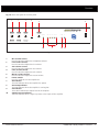
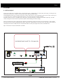
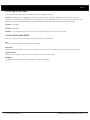
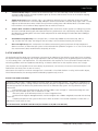
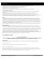
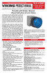
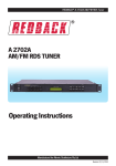
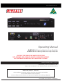
www.altronics.com.au
Operating Manual
A 4210 80VA Hearing Induction Loop Amplifier
A 4212 280VA Hearing Induction Loop Amplifier
SUITABLE FOR SIMPLE ONE AMPLIFIER DESIGNS.
NOT DESIGNED FOR COMPLEX MULTIPLE AMPLIFIER SYSTEMS.
NOT SUITABLE FOR INSTALLS WITH ADJACENT SYSTEMS.
Redback® Proudly Made In Australia
Distributed by Altronic Distributors Pty. Ltd.
Phone: 1300 780 999 Fax: 1300 790 999 Internet: www.altronics.com.au
IMPORTANT NOTE:
Please read these instructions carefully from front to back prior to installation.
They include important setup instructions.
Failure to follow these instructions may prevent the amplifier from working as designed.
User manual revision number: 1.0 26/05/2015
REDBACK is a registered trademark of Altronic Distributors Pty Ltd
Since 1976 Redback amplifiers have been manufactured in Perth, Western Australia by Altronics. With over 35 years
experience in the commercial audio industry, we offer consultants, installers and end users reliable products of high build
quality with local product support. We believe there is significant added value for customers when purchasing an
Australian made Redback amplifier or PA product
Australian Made Status
All Redback house products made by Altronics will now be sporting the official Australian Made logo. Since starting
manufacturing of commercial audio equipment in the mid 70’s we have always taken pride in producing a quality local
product.
The new adoption of the Australian Made logo will help us get the word out to local and export markets that our
products carry the official compliance seal of the Australian Made campaign. We have always pushed our ‘local is better’
line in all of our marketing efforts, it’s always an added boost when you are backed up by a widely recognised and
respected icon.
Industry leading 10 year warranty.
There’s a reason we have the industry leading DECADE warranty. It’s because of a long tried and tested history of bulletproof reliability. We’ve heard PA contractors tell us they still see the original Redford amplifier still in service in schools that’s over 37 years of operation - and still going strong!
Published by Altronic Distributors
© 2014 Altronic Distributors
2 Redback® Proudly Made In Australia
www.altronics.com.au
Contents
1.0 Overview
1.1 Introduction 4
1.2 Features 4
1.3 What’s in the box 4
1.4 Front panel guide 5
1.5 Rear panel connections6
2.0 Setup
2.1 Setup Guide7
2.2 EWIS Input8
2.3 DIP Switch Settings9
2.4 LED status indicators 9
3.0 Loop Design
3.1 Loop Design Guidelines10
3.2 The Loop10
3.3 Loop Types10
3.4 The Amplifier11
3.5 Theoretical Loops12
3.6 Practical Loops13
3.7 Steps In Loop Design13
3.8 Placement of Loops14
4.0 Terms and Abbreviations15
5.0 Specifications15
www.altronics.com.au
Redback® Proudly Made In Australia
3
Overview
1.0 OVERVIEW
1.1 INTRODUCTION
Induction Loop amplifiers, also known as T-loop or Hearing Loop amplifiers, are installed to greatly enhance the listening
experience of people using hearing aids. The hearing loop, as its name suggests, is basically a loop of wire which
surrounds a designated area to transmit audio to a hearing aid. An audio source is fed into the Amplifier, and the output
of the amplifier then sends a high current signal into the loop, which generates a magnetic field. The magnetic field is
then picked up by the Telecoil inside a hearing aid.
Hearing Loops are commonly installed in public areas which are generally noisy, making it difficult for hearing impaired
users to hear clearly. The A 4210 and A 4212 amplifier models have been engineered to meet AS60118.4-2007 and include a compressor/limiter circuit with tailored frequency response ensuring excellent speech intelligibility. They will
operate into loads of less than 2 ohms and are short circuit proof. Great for places of worship, community halls, museums
public places, etc.
The A 4210 80VA model delivers 3.5A RMS, 5 Amps peak and the A 4212 280VA model delivers 8A RMS, 11 Amps peak
into a typical Loop Resistance of 0.2Ω to 1.7Ω (max 2Ω).
The A 4210 is suitable for areas of approximately 180-200m2 subject to metal loss and the A 4212 is suitable for areas of
approximately 400-650m2 subject to metal loss.
Note that coverage may vary from site to site depending on outside influences such as steel reinforcement, high current
electrical wiring etc.
Inputs are provided for balanced mic and line, auxiliary and an EWIS input with VOX muting for interfacing into venue
emergency evacuation systems.
1.2 FEATURES
• Designed to meet AS60118.4-2007
• Coverage up to 180-200m2 for the A 4210 and 400-650m2 for the A 4212
• XLR line & mic inputs
• Aux input via stereo RCA
• EWIS signal connection (RCA)
• Short circuit proof
• Compressor for added speech intelligibility
• Adjustable VOX sensitivity
• Compatible with single loop designs
• 240V AC operation
• 19” Rack Mount (with optional A 4376 rack ears)
1.3 WHAT’S IN THE BOX
A 4210/12 Induction Loop Amplifier
240V AC IEC C13 Appliance Mains Lead 10A 3 Pin Black
Instruction Booklet
4 Redback® Proudly Made In Australia
www.altronics.com.au
Overview
1.4 FRONT PANEL GUIDE
Fig 1.4 shows the layout of the front panel.
1
2
3
4
5
6
80VA Hearing Loop Amplifier
Model : A 4210
Mic Vol
4
Line Vol
6
4
8
2
0
10
6
4
8
2
0
10
6
8
2
0
Power
Master
Aux Vol
4
6
0
10
10
Signal Present
-15dB
-9dB
-6dB
-3dB
0dB
Overtemp
On
8
7
8
2
Alert/Evac
Level
10
9
Fig 1.4
1
2
3
4
5
6
7
8
9
10
Mic volume control
Use this control to adjust the microphone volume.
Line volume control
Use this control to adjust the Line volume.
Aux volume control
Use this control to adjust the Aux volume.
Ewis volume control
Use this control to adjust the Ewis volume.
Master volume control
Use this control to adjust the master volume.
Power Switch
Use this switch to turn the amplifier on.
On Indicator
This LED indicates when the amplifier has power.
Overtemp Indicator
This LED indicates when the amplifier is running hot.
VU Indicator
These LED’s indicate the output level of the amplifier.
Signal Presence Indicator
This LED indicates when a signal is present at the inputs of the amplifier.
www.altronics.com.au
Redback® Proudly Made In Australia
5
Overview
1.5 REAR PANEL CONNECTIONS
Fig 1.5 shows the layout of the rear panel.
1
CAUTION
RISK OF ELECTRIC SHOCK
OPEN BY QUALIFIED
PERSONNEL ONLY
2
3
4
5
SW
1
!
Made in Australia by
Altronic Distributors Pty Ltd
+24V DC FUSE
DIP Switch Options
On
Off
Vox enabled
Vox disabled
Not Used
2
3
Not Used
4 Phantom Power On Phantom Power Off
OUTPUT
www.altronics.com.au
6
PHASE
SHIFT
-24V DC FUSE
L
L
R
R
DIP
Vox
Switches Sens.
2
1
2
1
3
3
Line
Mic
ON
1 2 3 4
+
–
(When Internal
module fitted.)
Ewis
Aux
10
9
240V AC @ 50Hz
8
7
Fig 1.5
1
+24V DC Fuse
This resettable fuse protects the positive supply rail inside the amplifier.
2
Output Connections
Connect the loop to these terminals.
3
-24V DC Fuse
This resettable fuse protects the negative supply rail inside the amplifier.
4
Phase switch
Not currently available. i.e. inactive.
5
Line Input
A 3 pin balanced Line level input.
6
Mic Input
A 3 pin balanced Microphone level input. Phantom power is also available on this input (see DIP switch settings).
7
EWIS input vox sensitivity
This trimpot adjusts the Vox sensitivity of the EWIS input. Once the VOX is activated the Mic, Line and AUX inputs will be overridden.
8
DIP Switches
These DIP switches set the phantom power and Vox enable options.
9
Aux Input
The AUX inputs are dual RCA connectors which are internally mixed to produce a mono input signal.
10
EWIS Input
The EWIS inputs are dual RCA connectors which are internally mixed to produce a mono input signal.
6 Redback® Proudly Made In Australia
www.altronics.com.au
Setup
2.0 SETUP
2.1 SETUP GUIDE
The A 4210 and A 4212 amplifiers have a total of four inputs. A balanced 3 Pin female XLR (Mic input), a balanced 3 Pin
female XLR (Line input), a dual RCA (Aux input) and a dual RCA (EWIS input).
The Microphone input has an input sensitivity of 100mV, while the Line, Aux and EWIS inputs have an input sensitivity of
1V. The Line input is suitable for connection from the Line Level output of another amplifier.
Phantom power (12V DC) is available at the Mic input, and VOX muting is available on the EWIS input only. (See DIP
switch settings for more info on the phantom power and enabling the VOX muting).
For best performance when using long lines between microphones and the amplifier use balanced lines. These reduce
noise or hum that may be induced into the cables. Note that a balanced line uses three wires (two signal wires and one
screened earth wire or shield) where an unbalanced cable uses only one signal wire and a screened earth.
Fig 2.0 illustrates the input connections available.
LOOP RESISTANCE (0.2Ω TO 1.7Ω. MAX 2Ω)
CAUTION
RISK OF ELECTRIC SHOCK
OPEN BY QUALIFIED
PERSONNEL ONLY
SW
1
!
DIP Switch Options
On
Off
Vox enabled
Vox disabled
Not Used
2
3
Not Used
4 Phantom Power On Phantom Power Off
Made in Australia by
Altronic Distributors Pty Ltd
www.altronics.com.au
+24V DC FUSE
L
L
R
R
PHASE
SHIFT
-24V DC FUSE
DIP
Vox
Switches Sens.
2
1
2
1
3
3
Line
Mic
ON
1 2 3 4
+
–
(When Internal
module fitted.)
Ewis
Aux
OUTPUT
240V AC @ 50Hz
REDBACK
CD
MODEL AC FUSE
5A
7.5A
OUTPUTS
100V
70V
4 -16Ω
INPUT
24V DC
Made in Australia by
Altronic Distributors Pty Ltd
24V DC
OUT
(1A Max)
4
6
0
–
+
–
+
+
–
2
8
2
–
LINE OUT
VOLUME
www.altronics.com.au
+
CAUTION
230V AC @ 50Hz
RISK OF ELECTRIC SHOCK
OPEN BY QUALIFIED
PERSONNEL ONLY
!
A 4370
A 4380
1
3
LINE IN
2
1
3
10
+ _
RESETTABLE
FUSE
Fig 2.0
www.altronics.com.au
Redback® Proudly Made In Australia
7
Setup
2.2 EWIS INPUT
The A 4210/12 amplifiers have a dedicated EWIS input for emergency situations.
A Fire Evacuation System can be configured when the A 4210/12 is complemented with an Emergency Tone Generator or
Evacuation Controller such as the Altronics A 4575A as shown in Fig 2.1.
The A 4575A controller is designed around industry standard building emergency alert/evacuate requirements. When
connected to a paging system amplifier, building occupants can be alerted and/or evacuated in the event of an emergency
e.g.: fire, gas leak, bomb scare, earthquake.
Figure 2.1 demonstrates how to connect the A 4575A controller to the A 4210/12 amplifier.
The output of the A 4575A Evacuation controller is connected to the EWIS Input of the A 4210 using dual RCA leads. The
output level of the signal from the Evacuation controller is set by the EWIS volume adjustment on the front of the
A 4210/12 amplifier.
The A 4210/12 has an in-built VOX circuit, which is activated when a signal is applied to the EWIS input. The VOX
sensitivity of the EWIS input is adjusted via the (Alert/Evac Level) trimpot adjustment on the front panel. Once the VOX
is activated the Mic, Line and AUX inputs will be overridden, and the audio from the EWIS input will be output. (See DIP
switch settings for more info on enabling the VOX Triggering).
A 4575A ALERT/EVAC CONTROLLER
1
2
3
4
5
6
7
8
+ _
A 4210/12 AMPLIFIER
CAUTION
RISK OF ELECTRIC SHOCK
OPEN BY QUALIFIED
PERSONNEL ONLY
SW
1
!
Not Used
2
3
Not Used
4 Phantom Power On Phantom Power Off
OUTPUT
Made in Australia by
Altronic Distributors Pty Ltd
www.altronics.com.au
DIP Switch Options
On
Off
Vox enabled
Vox disabled
+24V DC FUSE
-24V DC FUSE
L
L
R
R
PHASE
SHIFT
DIP
Vox
Switches Sens.
2
1
2
1
3
3
Line
Mic
ON
1 2 3 4
+
–
(When Internal
module fitted.)
Ewis
Aux
240V AC @ 50Hz
Fig 2.1
Other Emergency Tone Generators
A 2070B
Alert/Evac Tone Generator
A 1741
MP3/SD Tone Generator
8 Redback® Proudly Made In Australia
A 4572
Alert/Evac Tone Generator
A 4595
School Lockdown Controller
www.altronics.com.au
Setup
2.3 DIP SWITCH SETTINGS
These switches configure the phantom power and Vox triggering function.
Switch 1 - Enables the VOX Triggering. The VOX is activated when a signal is applied to the EWIS input. The VOX
sensitivity of the EWIS input is adjusted via the (Alert/Evac Level) trimpot adjustment on the front panel. Once the VOX is
activated the Mic, Line and AUX inputs will be overridden, and the audio from the EWIS input will be output.
Switch 2 - Not Used
Switch 3 - Not Used
Switch 4 - Sets the phantom power (12V DC). The phantom power affects the Mic input Only.
2.4 LED STATUS INDICATORS
There are a series of LED’s on the front panel which indicate the following.
On
Indicates when the amplifier has mains power applied.
Overtemp
Indicates when the amplifier reaches a high temperature. The unit will shutdown if this occurs, preventing damage.
Signal Presence
Indicates when a signal is present at any of the Mic, Line, Aux or EWIS inputs.
VU Meter
The dB output of the amplifier is indicated by the 0dB to -15dB LED’s.
www.altronics.com.au
Redback® Proudly Made In Australia
9
Loop Design
3.0 LOOP DESIGN
3.1 LOOP DESIGN GUIDELINES
Altronics does not guarantee absolute outcomes from following any specific information produced in these
instructions. This is purely a guide and assumes the Loop Design is made by someone with the appropriate
qualifications or experience.
Note: The most successful loops are designed with access to the site for measurements and proof of concept prior to
completion of facility. In the case of an existing venues, access limitations may lead to compromise in final performance.
In brief, Assisted listening Systems (ALS) include AM/FM Transmitters/Receivers, Infrared Transmitters/Receivers and
Induction Loop Systems. Most Hearing Aid Devices are available with the built-in Telecoil (T) option. No additional
equipment is required for the pickup of the Electro Magnetic signal therefore making them a versatile device for detecting
an electronic signal.
In Audio Frequency Induction Loops (AFILs), the signal is baseband audio and requires only a simple Telecoil pickup
(Hearing Aid fitted with T-coil). Listening (area) can be controlled by the loop layout and the system is not interrupted by
physical obstacles. On the down side the signal can be affected by mains borne interference, spill from adjacent loops and
variations of frequency response due to metal loss or localised variations in magnetic field strength. In Australia AFILs are
the most commonly deployed hearing assistance mechanisms.
Loop locations: Apart from public spaces as set down by the BCA, loops can be utilized in lifts, trains, taxis, domestic
locations (e.g. Living/lounge rooms), etc.
[These specifications relate to the vertical component of the magnetic field. The T-coil in hearing aids is
usually mounted vertically. Not all hearing aids comply with this standard which often causes complaints
about loop systems. Exceptions must be made in certain situations where the head of the listener is not
vertical (places of worship, hospitals and recovery areas as people may be kneel, prone or supine).]
3.2 THE LOOP
In its simplest form, is a copper conductor fitted to the perimeter of area in interest (fig 8 cable is very satisfactory). As
the installation gets more demanding due to metal loss (e.g. extensive use of reinforcement steel) and requirements for
tight control of spill, the loop design becomes more complicated including use of multiple amplifiers. For such applications
requiring low spill, high metal loss compensation designs, it is recommended that a consulting engineer with appropriate
experience be utilised. The A 4210/12 amplifiers are not intended for use in multiple amplifier designs.
As for the loop resistance, Altronics A4210 and A4212 Hearing Loop Amplifiers preferred load resistance range is 0.2Ω to
1.7Ω (inherently short circuit proof and stability guaranteed to 2Ω).
See “Loop Resistance” and cable choice under Practical Loop section for more information.
3.3 LOOP TYPES
1.
Counter Loops: Loops fitted to service/information counters e.g. Post Office, Doctors reception area, Rail Ticket
office, etc. Can be a simple matt style pre-manufactured unit or more effectively a combination vertical/horizontal coil fixture under the counter/desk structure of the facility driven by a small amplifier and microphone
combination.
2.
Perimeter Loop: Placing a loop typically at the edge (or 600mm in) of room boundary with a suitable feed
termination from amplifier. The loop wire resistance including feeder cable must meet requirements of amplifier specifications. Some problems may arise regarding metal loss and loop spill into adjacent areas. Never install the loop cable at head (Hear Aid) height as performance can be erratic due to field strength variation. Spill can be as far as 3.5 times width of loop, (rolling off then decaying to complete zero). Avoid installation of single Perimeter Loops in spaces larger than 10m x 10m, as the field strength will potentially have large variations. Plan for 2 or multiple loops.
10 Redback® Proudly Made In Australia
www.altronics.com.au
Loop Design
3.
2-Turn Perimeter Loop: A variation of the Perimeter loop is a 2-turn cable loop, which increases the field strength by 6dB, however the loop impedance goes up (4 times) and increases the risk of the amplifier clipping especially at high frequencies.
4.
Single Array Loop: Two or multiple “fig 8” type segments nominally 2 to 5m, preferably all the same width.
Requires less current than a Perimeter loop (3dB per 2 sections) but exhibits a brief but sharp signal “Null” at each
segment or cable crossover. Most suitable for a permanent seating areas and individual desks (Classroom setup). Has limitations as the number of loop segments due to metal loss increases.
5.
“Electric Grill” variation of the Perimeter Loop: Fitted as continuous sections approx. 2m wide giving a more
consistent field and lowering spill and improved metal loss performance. Uses substantially more cable, requires
considerations regarding lower resistance cable and potential for cable damage if fitted under floor cladding in heavy traffic area.
6.
Cancellation Loop (Passive): In the simplest form, a narrow loop added to a Perimeter Loop, laid as a
“fig 8”end of the main loop. The design of the extra loop is critical and best fitted by trial and error.
7.
Ultra Low Spill Array: With mathematical Simulation and extremely precise placement of loop components (down to <50mm) an Ultra-Low Spill System can be achieved with spill down to approx. 1m. A site visit for sample test measurements (data) would enhance the quality of results.
3.4 THE AMPLIFIER
The preferred amplifier design must incorporate a compressor for reduction of the dynamic range and a limiter to protect
the amplifier output from clipping (esp at high frequencies) and thus eliminating any risk of generating EMC transmissions
i.e. must comply with C-tick requirements. It is also preferred that the amplifier has a true current drive output and thus
minimizing problems with low impedance and driving an inductive load. Plan for the amplifier to have 20% margin.
[The amplifier must be capable of short term delivery of pulsed tone (125mS bursts) of current to achieve 400mA/m with
no distortion see extract from AS 60118.4-2007]
Please Note: The amplifier’s maximum coverage area is measured in a free field situation. In reality (with metallic objects,
like reinforced concrete) the coverage could be reduced by approximately 20-50%.
Extract from AS60118.4 (2007)
“Magnetic Field Strength in Audio-Frequency Induction Loops for Hearing Aid Purposes”: The rigorous standard for Audio Induction Loop Systems, making Australia internationally compliant in regard to field strength and audio quality for
the hearing impaired. This defines the performance criteria of an induction loop system. The key elements may be
summarised:
•
Field Strength in the specified listening area shall be -20dB re 1A/m average i.e. 100mA/metre long term average, using a 1kHz sinusoidal input, with a variation of +/-3dB.
•
short term peaks up to 400mAmps/metre (0.125secs integration time)
•
Environmental Magnetic Background noise shall be no higher than -40dB A-weighted (measured with the loop
system off).
•
Frequency Response of the system shall be from 100Hz to 5000Hz. The variation should be no more than +/3dB from the value taken at 1kHz.
The international standard is IEC 60118.4 (also known as SN, EN or BS 60118.4)
www.altronics.com.au
Redback® Proudly Made In Australia 11
Loop Design
In practical terms, the recommended field strength, based on Australian Standard 60188.4 (2007):
100mAmps/metre long term average (>60 secs) i.e. -12dB ref 400mA/m (rms)
400mAmps/metre (0.125secs) becomes 0dB ref and THD less than 1%.
Background noise -32dB A-weighted ref 400mA/m
Please note that this standard is about the ability of the amplifier to deliver correct current into loop.
The aim of AFILs is to obtain:
Reasonable magnetic field strength within the working area at ear level (1.2 metre sitting, 1.6 metre standing), per
AS60188.4.
Minimal overspill which could cause interference with other similar systems or compromise confidentiality
Acceptably uniform magnetic field strength over frequency range 100Hz to 5000Hz, as per AS60188.4. Signal
processing to achieve compression/limiting so that the variation in output level is limited in Dynamic Range and to ensure
that the amplifier never goes into clipping (severe distortion) thus creating unwanted EMC interference.
Metal:
The presence of metal within the fabric/structure of buildings has an impact on loop performance. When any magnetic
field generated, (by the audio loop in this case), Eddy currents are generated as a result within any metal structures
within the space. The induced currents will lower the main magnetic field in localized spots/areas causing degradation to
the audio signal level or modifications to the tonal balance resulting in lack of clarity at especially at higher frequencies.
The type of metal and the profile has a bearing on amount of loss. Examples of metallic structures include concrete floor
reinforcement, suspended ceilings, metal counters and lifts.
By careful attention to design and detail, the effects of metal can be minimised and sometimes completely eliminated.
Background Noise:
Measure the environmental background electromagnetic noise utilising a Field Strength Meter (FSM) with the loop
system off. The required figure is -32dB (re 400mA/m) ideally preferred if 47dB! Will accept -22dB as useable but report.
Hearing induction loop systems for large floor areas need to be carefully designed. Simple ‘perimeter loop’ layouts which
work well for small rooms with timber floors, are often not suitable for larger rooms. For example, loops installed in large
rooms built upon concrete slabs can suffer field strength and frequency response losses due to the presence of
structural steel reinforcement (or ‘reo’) laid within the slab. In order to provide an installed system which meets the
applicable Australian Standards (AS1428 and AS60118.4-2007) greater attention needs to be given to the site data, loop
design and implementation. Finally adequate signage must be utilised for compliance.
3.5 THEORETICAL LOOPS
Definition of AMP/METRE:
A field strength (FS) of 1 Amp/metre (1A/m) exists at the centre of a circular loop of one metre diameter when
a current of 1 Amp rms flows in the loop. (from H = I/2R, I = loop current, R = radius)
Square Loops:
For a square loop of one turn, the field strength at the centre is given, with “a” being the length of each side, by:
H = (2√2 / π) x (i / a)
Which means that a field strength of 100mA/m would be given by a current:
i = (0.1 x π x a)/ 2√2 = a/9 amps
Naturally this calculation gives the field strength (FS) only at the centre of the loop but we need to know about the
distribution of the field over the whole area of the loop. Refer to the cross section of loop below and notice that at the
centre the FS is lower than just inside the edge of loop wire on each side of perimeter.
12 Redback® Proudly Made In Australia
www.altronics.com.au
Loop Design
Fig 3.0
Cross section indicating Distribution of field strength
3.6 PRACTICAL LOOPS
Loop Resistance and Cable Choice: (as to be used with Altronics A4210 and A4212 amplifiers)
Loop Cable Types:
The loop cable can be figure 8 cable, copper foil or multi-wire as long as the resistance is compatible with the amplifier
requirements (preferred load resistance range is 0.2Ω to 1.7Ω). That includes feeder cable from amplifier location, all
terminations and the loop itself. In the simplest installation, the loop is terminated at the amplifier.
The fig 8 cables can be bulky under carpet utilising thinner underlay and other floor covering. Foil and ribbon has a very
low profile under carpet but are more prone to damage from excessive localised force or uneven flooring which moves
with loading.
The table shown below provides examples of Altronics’ cables which would be suitable.
•Figure 8 cable (Note Flexibility: Resistance per cable length can be halved by paralleling or used as 2 Turn Cable)
Altronics Cat
No:
Description
Max Current /
leg
Resistance/100m
Uses
W2119
7.5A
2.45Ω
Small-medium loops
W2135
10A
1.85Ω
Larger loops
W4052
Heavy Duty
17A
1.05Ω
Larger loops/feeder cable
W4154
Very HD (Feeder)
20A
0.45Ω
HD Feeder cable only
•Multi-wire ribbon
Altronics Cat No:
Description
W2616
16 wires 28AWG=1.296mm²
3.7 STEPS IN LOOP DESIGN (a suggested approach)
1.
2.
3.
4.
5.
6.
7.
8.
9.
10.
11.
12.
Decide location and measure loop size (length x width plus distance to Loop Drive Amplifier).
Check environmental (background) magnetic noise level (A-weighted) using Field Strength meter (FSM). This will be a combination of 50Hz Hum associated with proximity of mains cabling or switchboards and 100Hz Buzz caused by rectification or light dimmers.
Adjust location if required after noise level checks, any identified thoroughfares through the space and other
factors affecting the space.
Calculate average current in single turn to give 100A/m field strength, from i = a ÷ 9
Determine loop wire resistance (R) compatible with amplifier requirements
Determine amplifier drive characteristics to meet loop drive requirements
If possible, install/tape temporary loop into place on floor
Inject 1kHz tone into amplifier, adjust gain control to correct operating level (setting current for long term average Field Strength of 100mA/m.)
Confirm Frequency Response of system tone 100Hz and 5kHz at +/-3dB (unweighted)
Verify signal quality with FS at 400mA/m (approximate) Note: correct signal should be a pulsed tone
For reference and repeatable calibrations, manually plot long term FS readings in selected reference locations.
Fit appropriate signage for system compliance under BCA.
www.altronics.com.au
Redback® Proudly Made In Australia 13
Loop Design
As a starting point for typical Perimeter loops, the long term average current is approximately the length of the shorter
side divided by 9 and the max (short term) current is 12dB higher i.e. approx. 4 times the length of shortest side divided by
9.
3.8 PLACEMENT OF LOOPS
Optimum position for loop is at floor level (up to 250mm above) or under floor depending on access to floor covering
and floor structures or 2.4m to 3.5m above floor i.e. in suitable ceiling. (Bearing in mind the working area at ear level i.e.
1.2m sitting, 1.6m standing) However Loop Displacement, typically between 10% and 25% of loop width (up to 50% for
small room), can alter these figures for larger rooms especially for Perimeter loops. Keep cabling 500mm to 600mm away
from outside room border walls and preferably away from heavy traffic areas if placed under floor covering (protection of
cable). In some construction styles, the loop cable can actually be placed outside the room perimeter walls.
FINAL CHECKS:
Before an induction loop system is permanently installed, it is recommended that:
•
Environmental electromagnetic noise should be checked with the venue’s lights and all electrical systems turned on.
•
The loop wire should be temporarily taped or tacked in place and the system fully tested before performing final installation.
•
To check whether the loop system is interfering with audio-visual systems, the venue’s audio & video systems should be on when testing the loop.
•
If electric guitars are used, they should be checked during the pre-installation loop test in order to determine if their magnetic pickups are sensitive to the planned loop location. Use of Dynamic Mics to be confined outside of Loop area.
Fig 4.0 illustrates the typical frequency repsonse required.
Fig 4.0
14 Redback® Proudly Made In Australia
www.altronics.com.au
Specifications
4.0 TERMS AND ABBREVIATIONS
Terms and AbbreviationsExplanations
AFILs Audio Frequency Induction Loops
FS
Field Strength (Magnetic)
FSM
Calibrated Meter to indicate magnetic Field Strength (Baseband Audio)
T (“T” setting)
Telecoil
mA/m
(H) Magnetic Field strength measured in milliAmperes per metre
0.125secs integration time An extended processing time measurement for level meter (not readily
available but normal PPM reads approx. 30% higher)
dB L
Expressing dB levels in reference to Induction Loops
A-weighted
Filtered curve used for acoustic measurements
rms
Root-mean-squared (refers to sinewave signal level)
Spill
Unwanted magnetic signal transmitted outside the loop
5.0 SPECIFICATIONS
Measurements referenced to 1kHz
A 4210 drive current:
A 4212 drive current:
Loop requirements:
Frequency response:
THD:
Compressor:
Input:
Output:
Power:
Dimensions:
3.5A RMS, 5A Peak
8A RMS, 11A Peak
0.2Ω to 1.7Ω preferred range
100Hz to 5kHz @ -2dB, 80Hz to 6kHz @ -3dB target.
<0.25% @ 50% drive
2:1 for dynamics control (fast attack)
3 pin XLR, Stereo RCA
Loop connection via pluggable terminals
240V ac
432W x 380D x 88H
*Specifications subject to change without notice
www.altronics.com.au
Redback® Proudly Made In Australia 15
Warranty
All Australian made Redback products are covered by a 10 year warranty.
Should a product become faulty please contact us to obtain a return authorisation number. Please ensure you have all
the relevant documentation on hand. We do not accept unauthorised returns. Proof of purchase is required so please
retain your invoice.
Retail / Trade / Education & Government customers
Ph: 1300 797 007 Fax:1300 789 777
www.altronics.com.au
Sydney, NSW.
15 Short St, AUBURN,
NSW 2144
Sydney GPO MEGA MALL
20km
Open:
Mon-Fri 8.30am - 5.30pm
Sat 9.00am - 4.00pm
SHORT ST
rn
Aubu
E RD
GVAL
WESTALL RD
SPRIN
VAUXHALL
EA.
ST
MCDONALDS
SANDGATE
ia
ROAD
Virgin
ne
Brisba17km
GPO
Open:
Mon-Wed,Fri 8.00am - 5.30pm
Thur 8.00am - 8.00pm
Sat 8.30am - 5.00pm
Sun 10.00am - 4.00pm
PRITCHARD ROAD
Perth, WA.
e
bridg
North
FITZGERALD ST
174 Roe St, PERTH, WA 6000
JAMES ST
Perth GPO
1km
Open:
Mon-Wed,Fri 8.00am - 5.30pm
Thur 8.00am - 8.00pm
Sat 8.30am - 5.00pm
Sun 12.00pm - 5.00pm
ROE ST
RF
HA
W
YH
WY
ER
ST
CH
ET
HA
RF
ST
FL
ST
AN
ILA
ALB
LE
Unit 6, 1326 Albany Highway,
CANNINGTON, WA 6107
n
ingto
Cann
ST
Cannington, WA.
VE
LA
CI
W
N
O
AS
CE
ST
RO
CA
M
MITCHELL FWY
EL
GS
IN
NN
US
BU
tta
Balca
LEDGAR RD
ERINDALE RD
DEL
NEY
AW
ST
BOYA WAY
16 Redback® Proudly Made In Australia
’WAY
CENTRE RD
ROBINSON RD
Unit 2, 1870 Sandgate Rd,
VIRGINIA, QLD 4014
Open:
Mon-Fri 8.00am - 5.30pm
Sat 8.30am - 5.00pm
Sun 10.00am - 4.00pm
AV
CES H
Brisbane, Qld.
Unit 7, 58 Erindale Rd,
BALCATTA, WA 6021
RT CR
ALBE
PRIN
Open:
Mon-Fri 8.30am - 5.30pm
Sat 9.00am - 5.00pm
Sun 10.00am - 4.00pm
Balcatta, WA.
HARC
OURT
891 Princes Hwy, SPRINGVALE,
VIC 3171
KALM
GARDEN
INA AV
R
Melbourne, Vic.
Open:
Mon-Wed,Fri 8.00am - 5.30pm
Thur 8.00am - 8.00pm
Sat 8.30am - 5.00pm
DUCK ST
PARRAMATTA RD
www.altronics.com.au