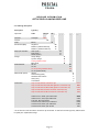
1
RELE ASE INFORM ATION OPTOCODE-II-CAN-ENCODER LINE Dear Customer This document informs you about the new encoder-line OCD II CANopen, that replaces the older OCD CAN series since the beginning of 2010. As you perhaps recognized, the received encoder has a different type key and is shorter than before. In the past we were forced to overhaul and redesign our CANopen encoder series, due to discontinuation and availability of some electronic components. This was also an attractive opportunity to improve the functionality of our CAN encoders series. Additionally we changed some details to gain conformity to manufacturer spanning standards released by the CAN in Automation e.V. user group. Unfortunately, these changes can lead to minor incompatibilities to the OCD version before. We expect, that these incompatibilities get noticed by only a few customers, who use the CAN communication in a specific way. In these cases, we are able to provide a simple procedure to set the new OCD-II-CA into a compatibility modus, that emulates the old behaviour. Several field tests at customers have successfully been completed. The following pages will inform you about: Enhanced Functionality Important Enhancement of the Product Portfolio (Through Hollow Shaft Encoder) Conformity to manufacturer spanning Standards and Device Profiles Simplified Product Range and consistent Typekey 10 mm shorter housing Please find the new datasheets and manuals on our homepage. For the beginning the datasheets of the older OCD series will stay on the website. If you have questions or problems please, do not hesitate to contact your Posital contact person. We want to offer you our best support in order to have a smooth and successful transition towards our new OCD II series. With kind regards Your Posital Team FRABA AG 1 RELE ASE INFORM ATION OPTOCODE-II-CAN-ENCODER LINE Technical information 1 Enhanced Functionality The new CA-encoder line will have enhanced functionality, as the following table shows: Layer Setting Services Velocity- and Acceleration-output Eight additional software programmable Cams Verify Configuration (Object 1020h) Customer specific data storage (4 Objects) Bootloader Event-triggered PDO Internal terminal resistor, controllable via SDO 1.1 Layer Setting Services The abbreviation LSS stands for Layer Setting Services and is an extension packet of the CANopen-Stack. This packet provides functions to find not configured encoders or encoders with unknown configuration in a CANopen network. This can be unequivocally done by vendor-ID, product code, serial- and revision number to set a new baud rate and node number. 1.2 Velocity- and Acceleration-output The new encoder line will be able to calculate the velocity and acceleration in real time and transmit it to the control. 1.3 Eight additional software programmable Cams The software of the encoder will simulate eight cams, whose value is free programmable. The reaching of these values will effect a message to the control. 1.4 Verify Configuration (Object 1020h) This additional object allows an easy administration of parameter configuration. A time stamp will be stored in this object with every reconfiguration. After a reenergising of the network the control can verify if any changes had been done. 1.5 Customer specific data storage The encoder provides a data area, that can be used by the customer for his own purposes e. g. to cache process data like position values. 1.6 Bootloader A bootloader allows to reprogram the encoder directly via the CAN Bus. This function can be used for firmware updates. 1.7 Event-triggered Process Data Object (PDO) This function gives the possibility to transmit process data depending on events. E. g. position values can be sent with a change of the position. FRABA AG 2 RELE ASE INFORM ATION OPTOCODE-II-CAN-ENCODER LINE 1.8 Internal terminal resistor, controllable via SDO A CAN-bus-terminal resistor of 120Ohm will be integrated in the new encoder series. The resistor can be switched galvanically isolated via object 3002h. The galvanic isolation is realized by MOS-FET. 2 Simplification of the type key 2.1 New type key for CAN encoders The notations C2, C5 and C6 have their origin in technology. The type key describes internal functional groups, without relevance for the customer. Mostly it leads to redundant information in the type key. The functional groups will be replaced by one single PCB, that fulfils all functions and hence leads to a simplification. Generally the transfer can be done by replacing C2, C5 and C6 by the letters CA. Please note, that the CA version is not fully downwards compatible. For reference see info in chapter 3. The following examples show the transcode (x is a wildcard, that replaces parameters, that are not important in this context. OCD-C2B1B-xxxx-xxxx-0CC OCD-CAA1B-xxxx-xxxx-XXX The old C2-Typekey contains redundant information. Both C2 and 0CC mean connection cap. In the new encoder line, the software-interface (CAN) and the electrical interface will separated clearly. The last three digits will contain additional information concerning the connection cap. For more details see chapter “Integration: Set Encoder + Connection Cap”. OCD-C5B1B-1x1x-xxxx –xxx OCD-CAA1B-1x1x-xxxx –xxx The C5 version was a multiturn encoder with plug or cable exit. OCD-C6B1B-001x-xxxx –xxx OCD-CAA1B-001x-xxxx -xxx The C6 encoder can be recognised by the singleturn resolution. 2.2 Integration: Set Encoder + Connection Cap We are about to restructure our typekey for connection cap encoders as well. The introduction will be in line with the new CANopen encoder series beginning of September. Currently this product type key is described by: „0149000090 Set encoder + connection cap“ where different encoder types cannot be distinguished at a glance. On request of some customers, we will combine the encoder type key and the connection cap type key into one as follows: FRABA AG 3 RELE ASE INFORM ATION OPTOCODE-II-CAN-ENCODER LINE As an example the set 0149000090: Set OCD-C2B1B-1213-C100-0CC + AH58-B1CA-3PG should be considered. The future type key will be generated by adding to the old encoder type key a new electrical connection class called „connection cap‟, indicated by the letter „H‟ and two more digits which result from the first two letters of the electrical interface from the old type key of the connection cap, OCD-CAA1B-1213-C100-HXX + AH58-B1CA-3PG, resulting in the final new type key: OCD-CAA1B-1213-C100-H3P IMPORTANT: To avoid wrong orders, the type key ending with -0CC will not exist any longer. In case of repair and replacement the encoder with the ending „ –HCC „ has to be ordered. Replacement means, that the old connection cap remains at the customer and an encoder without connection cap will be ordered. 2.2 Integration: Set Encoder + Reducing Adapter The application of a reducing adapter allows the reduction of the diameter of a blind hollow shaft encoder. It is reducible down to 6mm and is currently handled as „Set Encoder + Reducing Adapter‟. Until now, this was handled as “Set Encoder + Reducing Adapter“. In future the reduced inner diameter will become an integral part of the encoder type key: Example:: 0149000039 Set encoder + Reducing adapter (Full type key is „Set OCD-C5B1B-1213-B150-PA9+ Reducing adapter RR12‟) will become: OCD-CAA1B-1213-B120-PA9 FRABA AG 4 RELE ASE INFORM ATION OPTOCODE-II-CAN-ENCODER LINE 2.3 Ordering description: Description Type key Optocode OCD- CA A1 Interface Version CANopen CA Code Revolutions (Bits) Binary Singleturn B- __ _ _ _ _ _ _- ___ A1 B 00 Multiturn (4096 revolutions) Multiturn (16384 revolutions) Steps per revolution Shaft diameter 4096 (0,09°) 8192 (0,04°) 65536 (0,005°) Clamp flange Synchro flange Through Hollow Shaft Blind shaft 06 mm Mechanical options 10 mm 12 mm (Through Hollow Shaft) 15 mm (Hollow shaft) without Flange Connection 12 14 12 13 16 C S T B 06 10 12 15 0 Shaft sealing (IP66) Stainless steel version* S V Heavy Duty Customized H C Cap encoder without connection cap* Cap encoder with three PG cable glands in connection cap HCC H3P Cap encoder with two M20 cable glands in connection cap Cap encoder with one M12-connector connection cap H2M H1B Cap encoder with two M12-connector connection cap H2B Cable exit 1m, radial, open cable ends Cable exit 1m, axial, open cable ends CRW CAW Two 5pin. M12-Connectors Connector exit, radial, 5 pin male M12 PRN PRM Connector exit, axial, 5 pin male M12 Connector exit, axial, 9 pin D-Sub PAM PA9 * for the function of the encoder a connection cap is needed. To order this encoder type only makes sense for spare part / replacement usage. FRABA AG 5 RELE ASE INFORM ATION OPTOCODE-II-CAN-ENCODER LINE 3. Conformity to CiA-Norm and Compatibility To guarantee conformity to CiA standard the encoders had to be changed in a way, that they are not fully compatible to the old types anymore. Overview of the incompatibilities: LED-behaviour Object 1802h second TPDO Object 1000h Device Type is not 196h Restore command BCD-switch position 9 in the connection cap 3.1 LED-behaviour The behaviour of the diagnosis and error LEDs was modified to fulfil the DR303-3 CANopen Indicator Specification of the CiA-organisation: CAN Run LED State Description Flickering AutoBitrate/ LSS The auto-bitrate detection is in progress or LSS services are in progress (alternately flickering with run LED)1 Blinking PREOPERATIONAL The device is in state PREOPERATIONAL Single flash STOPPED Double flash The device is in state STOPPED Reserved for further use Triple flash Program/ Firmware A software download is running on the device download On OPERATIONAL ERR LED State Description Off No error The device is in working condition Flickering AutoBitrate/ LSS The auto-bitrate detection is in progress or LSS services are in progress (alternately flickering with run LED)1 Blinking Invalid General configuration error The device is in state OPERATIONAL Configuration Single flash Warning limit reached At least one of the error counters of the CAN controller has reached or exceeded the warning level (too many error frames) Double flash Error control event A guard event (NMT-slave or NMT-master) or a heartbeat event (heartbeat consumer) has occurred Triple flash Sync error The sync message has not been received within the configured communication cycle period time out (see object dictionary entry Quadruple flash Event-timer error An expected PDO has not been received before the event-timer elapsed On Bus off The CAN controller is bus off 1006h) FRABA AG 6 RELE ASE INFORM ATION OPTOCODE-II-CAN-ENCODER LINE 3.2 Boot-up-time The encoder line needs less time to send the Boot-Up message after switching on. Boot-up-time old OCD-series new OCD-II-series Ca. 3000ms Ca. 250 ms 3.3 Object 1802h In the past the second PDO could be parameterised by the object 1801h and 1802h. This is not consistent with the CiA standards and will be ended with the new encoder line. This means in the future the second PDO can only be parameterised via object 1801h. New versions C6, CA (CiA-Conform) Mode COB-ID 1800h PDO1 Asynchronous 180h 1801h PDO2 PDO3 Cyclic Optional Cyclic (not used in C6) 280h 1802h 380h Old versions C2 and C5 Mode COB-ID 1800h PDO1 Asynchronous 180h 1801h PDO2 PDO2 Cyclic Optional Cyclic (used in C2/C5) Not used! 280h 1802h 3.4 Objekt 1000h Device Type is not 196h Object 1000h contains a coded description of CAN devices. Until now 196h was written to all encoder types. According to the standards singleturn and multiturn must be distinguished: Singleturn Mutliturn 10196h 20196h 3.5 Restore Command In the past the restore command set the encoder to customised default values The restore command sets the encoder to POSITAL default values, which are defined in the user manual. Communication parameters like node number and baud rate are not restored. FRABA AG 7 RELE ASE INFORM ATION OPTOCODE-II-CAN-ENCODER LINE 3.6 Connection Cap BCD-switch setting “9” The, former undefined, BCD-switch setting “9” in the connection cap is used to set the encoder in a mode, that ignores the switch setting for baud rate and node number. The parameters can be modified by SDO messages and LSS, only. 3.7 C2-C5-Work-around With little limitations, the new OCD-II-encoder line will be compatible to the current version. It will be possible to use the old EDS-file for configuration purposes in the PLC with the new encoder and no errors will occur. Merely the enhanced functions, like velocity- and acceleration-output, will not be available. In case for unexpected problems, there is the possibility to set the CA-encoder in a compatibility mode, that will restore the old C2-C5-behavior. There are the following procedures to set this mode: Manual, with the BCD-switch in the connection cap: o Remove cap from encoder o o Set node number 97 Reconnect connection cap Both LEDs will glow in red. o o Remove connection cap again and set back to the needed node number Reconnect connection cap C2-C5-Behavior Via SDO-commando (Software): o Write the security code 47111147h to object 3030h subindex 0h. o o Set object 3030h subindex 1h to „ONE“ Hard- or Software RESET 3.8 Fully software compatible CA-variants for C2, C5 und C6 (e.g. for spare parts) In principle it is still possible to order CA types which are fully software back compatible to the old C2 and C5 versions. (CA is already fully software back compatible to C6). This is done by adding 2 more CA variants: OCD-CAC2B-xxxx-xxxx-xxx These additional CA variants should only be ordered in exceptional cases (e.g. for repairs) as we would like to minimize the numbers of variants that we offer. FRABA AG 8