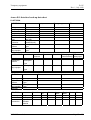
1
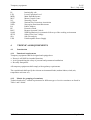
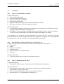
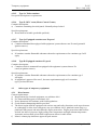
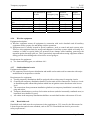
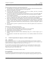
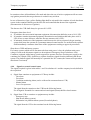
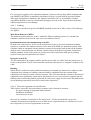
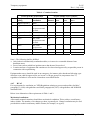
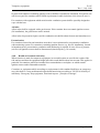
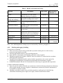
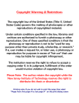
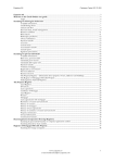
NORSOK STANDARD
TEMPORARY EQUIPMENT
Z-015
Rev. 1, July 1998
This NORSOK standard is developed by NTS with broad industry participation. Please note that
whilst every effort has been made to ensure the accuracy of this standard, neither OLF nor TBL or
any of their members will assume liability for any use thereof. NTS is responsible for the
administration and publication of this standard.
Norwegian Technology Standards Institution
Oscarsgt. 20, Postbox 7072 Majorstua
N-0306 Oslo, NORWAY
Telephone: + 47 22 59 67 00 Fax: + 47 22 59 67 29
Email: [email protected] Website: http://www.nts.no/norsok
Copyrights reserved
Temporary equipment
Z-015
Rev. 1, July 1998
CONTENTS
FOREWORD
2
1 SCOPE
3
2 NORMATIVE REFERENCES
3
3 DEFINITIONS AND ABBREVIATIONS.
3.1 Definitions
3.2 Abbreviations
4
4
4
4 TECHNICAL REQUIREMENTS
4.1 Introduction
4.2 Containers
4.3 Other types of temporary equipment
4.4 Technical requirements for temporary containers/ equipment
4.5 Interface for hook-up
4.6 Documentation
5
5
8
11
16
25
26
ANNEX A: ADMINISTRATIVE GUIDELINES (INFORMATIVE)
28
ANNEX B: DATA SHEETS AND CHECKLISTS (INFORMATIVE)
32
NORSOK standard
Page 1 of 36
Temporary equipment
Z-015
Rev. 1, July 1998
FOREWORD
NORSOK (The competitive standing of the Norwegian offshore sector) is the industry initiative to
add value, reduce cost and lead time and eliminate unnecessary activities in offshore field
developments and operations.
The NORSOK standards are developed by the Norwegian petroleum industry as a part of the
NORSOK initiative and supported by OLF (The Norwegian Oil Industry Association) and TBL
(Federation of Norwegian Engineering Industries). NORSOK standards are administered and issued
by NTS (Norwegian Technology Standards Institution).
The purpose of NORSOK standards is to contribute to meet the NORSOK goals, e.g. by replacing
individual oil company specifications and other industry guidelines and documents for use in
existing and future petroleum industry developments.
The NORSOK standards make extensive references to international standards. Where relevant, the
contents of a NORSOK standard will be used to provide input to the international standardisation
process. Subject to implementation into international standards, the NORSOK standard will be
withdrawn.
Annexes are informative.
NORSOK standard
Page 2 of 35
Temporary equipment
1
Z-015
Rev. 1, July 1998
SCOPE
The purpose of this standard is to specify the technical and safety related minimum requirements for
temporary equipment to be used on all installations in the North Sea.
2
NORMATIVE REFERENCES
The following standards include provisions which, through references in this text, constitute
provisions of this NORSOK standard. Latest issue of the references shall be used (see note 1 below)
unless otherwise agreed. Other recognised standards may be used provided it can be shown that they
meet or exceed the requirements of the standards below.
DBE
DLI
DLI
DLI
Rules for boilers.
Order number 192: Compressed air systems (Norwegian text only)
Order number 515: High-pressure cleaning etc. (Norwegian text only)
Order number 522: Machinery regulations. (Norwegian text only)
DNV
Certification Note No. 2.7.1: Offshore freight containers design and certification.
See Note 2 below.
EN 792
Hand-held non-electric power tools - safety requirements.
IMDG
International Maritime Dangerous Goods Code.
NFPA 72 E
Automatic fire detectors.
NORSOK E-001
NORSOK H-001
NORSOK R-001
NORSOK S-DP-001
NORSOK S-002
NOROSK S-DP-003
NORSOK Z-DP-002
NORSOK Z-001
NORSOK Z-010
Electrical Systems.
HVAC - Heating, Ventilation, Air Condition.
Mechanical Equipment.
Technical safety (will be renumbered S-001).
Working Environment.
Environmental care (will be renumbered S-003)
Coding system.
Documentation for Operation (DFO).
Electrical, instrumentation and telecommunication installation.
NPD
NPD
NPD
Regulations relating to electrical installations in the petroleum activities.
Regulations for systematic follow-up of the working environment (SAM).
Regulations relating to process and auxiliary facilities.
NS-EN 418
Safety of machinery - Emergency stop equipment, functional aspects principles of design.
NORSOK standard
Page 3 of 35
Temporary equipment
Z-015
Rev. 1, July 1998
Note 1: Specific references in this NORSOK standard to clauses, paragraphs or sections in
normative references may not be correct for normative references revised after issue of this
standard. This is, however, not intended to preclude use of latest issue.
Note 2: The reference to classification society rules applies to the technical provisions only. Any
requirement therein for classification, certification or third party verification is not part of this
NORSOK standard, and may be considered as a separate service.
3
DEFINITIONS AND ABBREVIATIONS.
3.1
Definitions
Temporary equipment: Equipment for limited use offshore, which require hook-up for use and/or
can be an ignition source.
Shall
Should
May
Can
Hot work
Verbal form used to indicate requirements strictly to be followed in order to conform
to the standard and from which no deviation is permitted, unless accepted by all
involved parties.
Verbal form used to indicate that among several possibilities one is recommended as
particularly suitable, without mentioning or excluding others, or that a certain course
of action is preferred but not necessarily required.
Verbal form used to indicate a course of action permissible within the limits of the
standard.
Verbal form used for statements of possibility and capability, whether material,
physical or casual.
Hot work embraces work operations where a source of ignition is used or caused.
Sources of ignition are generally divided into groups A and B, where B sources are
easier to control:
• Examples of type A ignition sources: Welding, hot tapping of pipes and tanks, hot
shrinking using open flame, preheating, flame cutting and grinding.
• Examples of type B ignition sources: Hot shrinking with electric hot-air drier, sand
blasting, electrical hand tools, megger testing, soldering iron, camera with flash and
non-Ex certified electrical appliances and peening.
3.2
ABE
Abbreviations
Fire extinguishers - approved for flammable liquids, fires in wood, paper,
fabrics or electrical equipment up to 1000 volt
CCR
Central Control Room
DBE
Directorate for Fire and Explosion Protection (Norwegian)
DLI
Directorate for Labour Inspection (Norwegian)
ESD
Emergency Shut Down
HVAC
Heating, Ventilation and Air Conditioning
IE
Instrumentation and telecommunication earth
IMDG
International Maritime Dangerous Goods
NORSOK standard
Page 4 of 35
Temporary equipment
IS
LEL
MER
MCC
NC
NFPA
NPD
PA
PE
ROV
SAM
SELV
SJA
UPS
Z-015
Rev. 1, July 1998
Intrinsically safe
Lower Explosion Level
Main Earth Reference
Motor Control Centre
Normally Closed
National Fire Protection Association
Norwegian Petroleum Directorate
Public Address
Protective Earth
Remote Operated Vehicle
NPD Regulations for systematic follow-up of the working environment
Safety Extra Low Voltage
Safe job analysis
Uninterruptible Power Supply
4
TECHNICAL REQUIREMENTS
4.1
Introduction
4.1.1 Functional requirements
Temporary equipment shall be designed and equipped too:
• Ensure it will fulfil its intended functions
• Avoid jeopardising the safety of personal and permanent installations
• Be safely transported
All temporary equipment shall comply with regulatory requirements.
The requisitioned shall specify the relevant environmental loads (outdoor/indoor, wind, rain,
temperature min/ max etc).
4.1.2 Matrix for grouping of containers
Technical and safety - related requirements for different types of service-containers are listed in
Table 1 and 2 below.
NORSOK standard
Page 5 of 35
Temporary equipment
Z-015
Rev. 1, July 1998
Table 1 - Matrix for containers in unclassified area
L
M
N
O
P
Q
R
M = Mandatory
R = Recommended
NORSOK standard
M
M
M
6
M
M
M
M
M
M
6
M
M
M
M
M
M
6
M
M
M
6
M
M
M
6
M
12
M
6
M
6
M
M
M
M
M
M
M
M
M
Note 1
M
M
M
M
M
M
M
M
M
M
M
M
R
M
M
M
M
M
M
M
M
M
M
M
M
M
M
M
M
M
M
M
M
M
M
M
M
M
M
M
M
M
M
M
M
M
M
M
M
M
M
M
M
M
M
M
M
R
R
M
M
M
M
M
M
M
M
M
M
M
M
Ex-inst. internal - Note 1
R
Gas alarm
M
Fire detection & protection
M
Ignition source disconnected
6
Gas detector -
M
Fire hose
M
M
M
Room extinguisher system
Note 2
Emergency exit -
M
M
Portable extinguisher
Note 2
No. of air changes/hour Note 2
K
Mechanical vent.- Note 1
J
Ex-inst. external
I
Emergency lighting
H
Telephone
F
PA
E
R
M
M
4.4.7
HVAC
M
M
M
4.4.6
Electrical
M
M
M
4.4.5
Tele
Manual alarm
D
4.4.4
Signal CCR
M
Sprinkler
C
4.4.3
Gas
Fire detection
B
TYPE CONTAINER
Accommodation
4.2.1
A-60 M
container
Offices, Coffee
4.2.2 bar, Laboratory
A0 M
Logging etc.
Workshop for
4.2.3
A0 M
hot work
Comprimator/
4.2.4
trashhandling
Workshop for
4.2.5
A0 M
cold work
Container for
4.2.6
A0
diesel engines
Control cont.
4.2.8
A0 M
ROV units
Storage for
4.2.9 flammable
A0
materials
Storage for non
4.2.10 flammable
materials
4.2.11 Paint storage
A0
Workshop for
4.2.12
A0 M
painters
Chill/freeze
4.2.13
A0
container
Radio/comm.
4.2.14
A0 M
container
4.2.15 Toilet container A0 M
MCC electrical
4.2.16
A0
container
Equipped cont.
4.2.17
A0
non-ex.
Equipped cont.
4.2.18
A0
ex-proof
4.4.2
Fire
Self closing door
A
4.4.1
Structure
Fire class/Rating
REQUIREMENTS
M
M
M
M
M
M
M
M
M
M
M
M
M
M
R
M
R
M
M
M
R
R
M
M
R
6
M
M
6
M
M
M
Note 1: The requirements of gas detector, Ex-relating
ventilation, see also 4.4.6.4
Note 2: The requirements might be depending of
circumstances, ref. to relevant section 4.4.x
Page 6 of 35
Temporary equipment
Z-015
Rev. 1, July 1998
Table 2 - Matrix for containers in hazardous area
J
K
L
M
N
O
P
Q
R
M = Mandatory
R = Recommended
NORSOK standard
M
M
M
M
M
M
M
M
M
M
10
M
M
M
M
6
M
M
M
M
6
M
M
M
10
M
6
R
M
M
M
M
M
M
M
M
M
M
M
M
M
M
Ex-inst. internal - Note 1
M
10
Ex-inst. external
M
M
Emergency lighting
M
Gas/alarm
Ignition source disconnected
Gas detector - Note 1
Room extinguisher system
Portable extinguisher
Fire detection
Self closing door
M
Overpressure (0.25 mbar)
I
M
4.4.7
HVAC
No. of air changes/hour Note 2
H
M
4.4.6
Electrical
Mechanical vent. - Note 1
G
4.4.5
Tele
Telephone
E
TYPE CONTAINER
Accommodation
4.2.1
Only for placement in non-hazardous area
container
Offices, Coffee
4.2.2 bar, Laboratory A0 M R/M M M M
M M
Logging etc.
Workshop for
4.2.3
A0 M R/M M M M
M M
hot work
Comprimator/
4.2.4
Only for placement in non-hazardous area
trashhandling
Workshop for
4.2.5
A0 M
M
M
M M
cold work
Container for
4.2.6
A0
M M M M M M
diesel engines
Control cont.
4.2.8
A0 M R/M M M M
M M
ROV units etc.
Storage for
4.2.9 flammable
A0
R M M
M
materials
Storage for non
4.2.10 flammable
M
M
materials
4.2.11 Paint storage
A0
M M M
M
Workshop for
4.2.12
Only for placement in non-hazardous area
painters
Fridge/freeze
4.2.13
Only for placement in non-hazardous area
container
Radio/comm.
4.2.14
Only for placement in non-hazardous area
container
4.2.15 Toilet container A0 M
M
M
R M
MCC electrical
4.2.16
A0
R/M M M M
M M
container
Equipped
R/M M
M M
4.2.17 container non ex- A0
proof
Equipped
4.2.18 container exA0
M
M
proof
4.4.4
Signal CCR
PA
D
4.4.3
Gas
Fire detection & protection
C
4.4.2
Fire
Loss of pressurization
B
Air lock - Note 2
Fire class/Rating
A
Emergency exit - Note 2
4.4.1
Structure
Note 2
REQUIREMENTS
M
M
M
M
M
M
M
M
R
M
R
M
M
M
R
R
M
M
R
10
M
M
M
6
M
M
M
M
Note 1: The requirements of gas detector, Ex-relating
ventilation, see also 4.4.6.4
Note 2: The requirements might be depending of
circumstances, ref. to relevant section 4.4.x
Page 7 of 35
Temporary equipment
4.2
Z-015
Rev. 1, July 1998
Containers
4.2.1 Type A: Accommodation container
Container description:
a) Cabins and corridors/ halls.
b) Mess room and recreation rooms.
c) Sanitarian, wardrobes and laundries.
d) Galley, bakery and kitchen.
e) Hospitals. NB: Special requirements not specified in this document.
f) Other types of rooms used for living purposes onboard.
Special requirements:
a) Accommodation containers shall always be located in a non-hazardous area and shall never have
openings of any kind leading to a hazardous area.
b) Fire dampers: Duct penetrations in building components having fire class A which are minimum
750 cm2 in cross-section shall be provided with an approved automatic fire damper.
A fire damper is not needed if the duct penetration is less than 750 cm2. In that case the duct
penetration shall, for a coherent length of 900 mm, be of minimum 3 mm gauge steel. This length shall
be insulated to the same fire resistance as the adjoining building component.
4.2.2 Type B: Offices, coffee bar, laboratory, well services, etc.
Container description; manned containers assumed to contain ignition sources such as:
a) Laboratories.
b) Offices.
c) Well service containers.
d) Calibration units.
e) Pressure safety valves calibration units.
f) Coffee bar.
Special requirements:
a) Coffee bars shall always be located in a non-hazardous area.
4.2.3 Type C: Workshop for hot work
Container description:
a) Workshop for different types of construction work including hot work purposes.
Special requirements:
a) If gas bottles are stored in the container then a warning notice to this effect shall be
posted outside, beside the entry door.
b) If work is causing air pollution, spot extractors shall be installed.
c) Hot work class “A” is not permitted (see subclause 3.1).
NORSOK standard
Page 8 of 35
Temporary equipment
Z-015
Rev. 1, July 1998
4.2.4 Type D: Compactor and trash handling units
Container description:
a) Trash containers which also include compactor.
Special requirements:
a) Equipment to be equipped with "dead man" emergency stop button.
4.2.5 Type E: Workshop for cold work
Container description:
a) Workshop for different types of construction work without ignition sources and ignition
potentials.
b) Manned tool container for non-flammable materials/tools.
4.2.6 Type F: Containers containing diesel motor in non-hazardous area
Container description:
a) Containers being built for containing diesel motor in non-hazardous area.
Special requirements:
a) Requirements for diesel motor, see subclause 4.3.1.
b) Diesel motor shall have emergency stop outside container.
c) If no ventilation of the container or no Ex-rating of the equipment, only location as per item 8 in
table 4 subclause 4.4.6.4 is acceptable.
4.2.7 Type G: Container for diesel motor in a hazardous area (zone 2)
Container description:
a) Containers containing a diesel motor installed in a hazardous area, limited to zone 2.
Special requirements:
a) Requirements for controls on a diesel motor, see subclause 4.3.
b) Requirements for air inlets, see subclause 4.4.7.
c) Diesel motor shall have emergency stop outside container.
d) For a container with a diesel motor located in zone 2, the following special requirements shall
apply: All equipment in container shall be approved for use in zone 2 area, or container shall be
pressurised. With the pressurised solution the ventilation is to be sufficient for cooling
requirement of the container. The diesel motor shall have its own air inlet duct for combustion
air. Ignitions sources shall be disconnected when gas is detected or pressurisation in container is
lost.
e) Motor exhaust temperature shall not exceed 300 deg C. Engine surface temperature of exhaust pipe
shall not exceed 200 deg C (T3). Test readings shall be a part of the required documentation.
4.2.8 Type H: Control container for ROV unit
Container description:
NORSOK standard
Page 9 of 35
Temporary equipment
a)
Z-015
Rev. 1, July 1998
Containers used for ROV control units.
4.2.9 Type I: Storage for flammable materials
Container description:
a) Containers being used for storage of flammable materials, except products requiring container
type K (ref. subclause 4.2.11).
4.2.10 Type J: Storage for non-flammable materials
Container description:
a) Containers being used for storage of non-flammable materials.
b) Tool container not manned or equipped for work operations.
4.2.11 Type K: Paint storage containers
Container description:
a) Containers being used for storage of paint and hazardous materials.
b) Containers for storage of materials in unopened wrapping, and other product types
that cannot emit solvent vapours. All opening of wrappings or storage of products that can emit
solvent vapours shall occur in container type L (ref. subclause 4.2.12).
4.2.12 Type L: Painter's workshop
Container description:
a) Containers where open contact with paint and solvents is possible.
Special requirements:
a) Containers shall always be placed in a non-hazardous area.
b) Inside the container is deemed as a hazardous area. Zone category shall be determined based on
the product emissions of flammable or explosive gases and the exposure time if emission occurs.
Electrical equipment shall be approved for groupe II B and temprating T3 (200° C) as a minimum.
c) Requisitioner has to specify special HVAC requirements.
4.2.13 Type M: Chill and freeze containers
Special requirements:
a) Containers for chill and freeze purposes shall always be located in a non-hazardous area.
b) The door shall also be possible to be opened from the inside.
c) An alarm shall be provided for personnel who are trapped inside.
4.2.14 Type N: Radio and communication room
Container description:
a) Containers used as room for radio and communications equipment.
Special requirements:
a) Only for location in non-hazardous area.
NORSOK standard
Page 10 of 35
Temporary equipment
Z-015
Rev. 1, July 1998
4.2.15 Type O: Toilet container
No special description or requirements
4.2.16 Type P: MCC room (Motor Control Centre)
Container description:
a) Containers containing electrical panels. Normally always locked.
Special requirements:
a) Doors shall be lockable (preferable pad lock).
4.2.17 Type Q: Equipped container non Ex proof
Container description:
a) Container unmanned but equipped with equipment/ systems that are non-Ex rated (potential
ignition sources).
Special requirements:
a) If container contains flammable substances then also requirements as for container type I will
apply.
4.2.18 Type R: Equipped container Ex proof
Container description:
a) Container which is unmanned but equipped with equipment/ systems that are Ex
rated (no ignition sources).
Special requirements:
a) If container contains flammable substances then also requirements as for container type I
will apply.
b) If equipment is approved for zone 2, the same requirements apply as for container
type Q in classified area.
4.3
Other types of temporary equipment
4.3.1 Diesel motors
General requirements:
a) Requirements for electrical equipment, see subclause 4.4.6.
b) For frame and lifting gear see subclause 4.4.1.
c) Noise abatement in accordance with SAM-regulations.
d) Good vibration dampening shall be provided.
e) The diesel engine shall be equipped with various stop and safety functions, such as gas detector
in combustion air inlet, local emergency stop (see subclass 4.4.8), platform remote stop (e.g.
platform ESD-system) and miscellaneous engine protections. Engine protections shall at least
include low lube oil pressure, high cooling water temperature and high exhaust temperature.
Automatic actions shall at least fulfil requirements shown in table below.
f) Motor's exhaust pipe shall have approved spark arrester.
NORSOK standard
Page 11 of 35
Temporary equipment
Z-015
Rev. 1, July 1998
g) Use of threaded or welded connectors is preferred. If flanged connectors are used, they shall be
equipped with fire-proof gasket.
h) Pneumatic start of motors preferred, alternatively electrical starter. In case of electric starter,
battery shall be fitted with battery circuit breaker for disconnection of ignition source see
subclause 4.4.3.
i) Flooding from diesel pump shall not be routed to pump feed chamber, but back to diesel tank.
Return area shall be screened off and aired to avoid continuous agitation of diesel and pressure
build-up in tank.
j) Drip pan below motor shall be provided with to collect any oil or diesel leaks.
k) All oil and diesel lines shall be made of metal pipes or reinforced hydrocarbon resistant material
(armoured hoses).
l) Oil refill cap and level indicator to be protected from coming loose in operation.
Gas detection in
air inlet
Stop engine
Automatic closure of air
inlet
Close diesel supply valve
Disconnect el. power supply
Isolate ignition sources
a)
b)
c)
d)
e)
X
X
X
X
X
Local
Platform
emergency stop remote stop
(ESD)
X
X
Engine
protection
X
X
X
Additional requirements for diesel motor located in zone 2:
For diesel motors in container, see subclause 4.2.7, special requirements.
Fan belts to be anti-static.
Fans to be made of non sparking material.
Electrical systems on diesel motor not installed in container shall be Ex approved, see subclause
4.4.6.
Motor exhaust temperature not to exceed 300 deg. C. Engine surface temperature and exhaust
pipe shall under no circumstances to exceed 200 deg. C (T3). Test readings shall be a part of the
required documentation.
4.3.2 Air compressors
Equipment description:
Diesel driven or electric driven compressor unit for supply of compressed air.
Requirements for controls:
a)Requirements for diesel motors, see subclause 4.3.1.
b) The compressor shall be equipped with various stop and safety functions, such as gas detector in
air inlet, local emergency stop (see subclause 4.4.8), platform remote stop (e.g. platform ESDsystem) and miscellaneous compressor protections. Compressor protection shall at least include
overspeed, low oil pressure and high temperature of cooling medium. Automatic actions shall at
least fulfil requirements shown in table below.
c) For frame and lifting gear see subclause 4.4.1.
d) Noise abatement in accordance with SAM regulation.
NORSOK standard
Page 12 of 35
Temporary equipment
Z-015
Rev. 1, July 1998
Gas detection in
air inlet
Stop compressor
Automatic closure of air
inlet
Disconnect el. power supply
Isolate ignition sources
X
X
X
X
Local
Platform
emergency stop remote stop
(ESD)
X
X
X
Engine
protection
X
X
X
Requirements for compressor section:
a) Air shall be taken from non-hazardous area.
b) Automatic stop if gas is detected in air inlet, in case of overspeed, low oil pressure or high
temperature in cooling medium. Local emergency stop and remote shut-down (platform
emergency shut-down system)
c) Fan belts shall be anti-static.
d) Drip pan shall be provided.
See also regulations to the working environment law issued by Directorate for Labour Inspection,
order number 192: "Compressed air systems".
4.3.3 Vessels/ tanks
Requirements for equipment:
a) Vessels tanks shall be approved, maintained and tagged/labelled according to IMDG code.
b) For frame and lifting gear, see subclause 4.4.1.
c) Vessels/tanks shall have earthing studs.
d) Interface for hook-up shall comply with the requisition.
4.3.4 High pressure cleaning equipment
Equipment description:
a) High pressure cleaning equipment means equipment where either fluid, fluid and steam or fluid
and abrasive/polishing medium under pressure, will be released as a jetspray through a pipe or
nozzle into free air
b) Fluid can be cold or heated.
Requirements for equipment:
a) For frame and lifting gear, see subclause 4.4.1.
b) If chemicals are used as an additive to the cleaning fluid then the nozzle assembly shall be earthed
c)
The equipment shall be equipped with safety devices like pressure safety valves, pressure
regulator and by-pass valve.
d) Equipment shall have an emergency stop device - easily visible
e) The high pressure nozzle to be equipped with an operating device which will automatically shut
off the jet (dead mans device), should the device be dropped or mishandled. The same principle
applies to a foot pedal operated unit.
NORSOK standard
Page 13 of 35
Temporary equipment
Z-015
Rev. 1, July 1998
f) The reaction force of hand held equipment shall not exceed 250 N.
g) On heated equipment there shall be installed two safety devices against overheating.
h) Heating of fluid/steam by electric power is preferred.
The above conforms with regulations to the working environment law issued by Directorate for
Labour Inspection, order number 515: ”Highpressure cleaning etc.”
4.3.5 Steam generator
Equipment description:
a) Boiler to supply superheated water or steam (above 100 deg C) normally heated by electrical
heater or diesel burner.
Requirements for boiler with diesel burner:
a) For frame and lifting gears, see subclause 4.4.1.
b) Boiler to be designed and built to comply with Directorate for Fire and Explosion Protection
(DBE) rules.
c) The steam generator (diesel burner) shall be equipped with various stop and safety functions,
such as gas detector in air inlet, local emergency stop (see subclause 4.4.8), platform remote
stop (e.g. platform ESD-system) and miscellaneous diesel burner protections. Diesel burner
protection shall at least include flame guard and low water level. Automatic actions shall at
least fulfil requirements shown in table below.
d) Exhaust temperature to surroundings shall not exceed 300 deg C. Surface temperature shall
under no circumstances exceed 200 deg C. Test readings shall be a part of the required
documentation.
e) Exhaust pipe shall have fireproof packings between flanged connectors, but use of threaded or
welded connectors is preferred.
f) Approved spark arrester shall be fitted in exhaust pipe.
g) All electrical equipment to be approved for use in zone 1, apparatus gasgroup II A, temperature
category T3.
h) Flooding from diesel pump shall not flow directly to pump feed chamber but back to diesel tank.
Return area shall be protected and aired to avoid continuous agitation of diesel or pressure buildp in tank
i) Drip pan shall be installed below burner unit to collect any diesel leaks.
j) Fans shall be of non-sparking material.
k) All oil and diesel lines to be made of metal pipes or reinforced hydrocarbon resistant material
(armoured hoses).
l) Permanent fire extinguisher system with automatic and external manual release and minimum one
fire extinguisher type ABE 12 kg to be provided.
m) Safety valves to be certified and maintained.
n) Unit shall be equipped with alarm for low water level.
o) Burner shall be equipped with flame guard.
NORSOK standard
Page 14 of 35
Temporary equipment
Z-015
Rev. 1, July 1998
Gas detection in
air inlet
Stop diesel burner
Automatic closure of air
inlet
Close diesel supply valve
Disconnect el. power supply
Isolate ignition sources
Pressure relief
X
X
X
X
X
X
Local
Platform
emergency stop remote stop
(ESD)
X
X
X
X
X
Engine
protection
X
X
X
X
X
4.3.6 Wireline equipment
Equipment description:
a) Wireline equipment means all equipment in connection with work downhole and all auxiliary
equipment used to prepare for and during wireline operations.
b) Equipment used is usually located in special containers, such as control and main system units.
There are also equipment units for storage and shipment of auxiliary systems which are usually in a
container or fitted on special skids, but protected from damage under handling, protected with
tarpaulin against chemical spills etc. This is particularly important when storing equipment offshore
during periods when drilling and well activities are not going on.
Requirements for equipment:
a) For frame and lifting gear, see subclause 4.4.1.
4.3.7 Subdistribution boards
Equipment description:
a) For temporary electrical power distribution and mobile socket units used in connection with major
modifications or inspections or similar
Requirements for equipment:
a) Usually temporary distributions shall be equipped with a socket setup for outgoing circuits.
b) Generally the temporary distribution boards or socket units will be connected to a socket or circuit
in distribution panel onboard the platform which has an ignition source shut-down at the lowest
level.
c) The connections from permanent installation (platform) to temporary installation is normally by
plug and socket.
d) Temporary distributions or sockets for location out-doors (and also in naturally ventilated areas) or
hazardous areas shall be Ex proof.
e) All outlets in the temporary distribution shall have an earth fault breaker with current of 30 mA.
4.3.8 Hand-held tools
Hand-held tools shall meet the requirements in the regulation no. 522, issued by the Directorate for
Labour Inspection and relevant standards, such as EN 792 "Hand-held non-electric power tools safety requirements".
NORSOK standard
Page 15 of 35
Temporary equipment
Z-015
Rev. 1, July 1998
Electrical equipment, hand tools, requirements and check list:
a) All hand lamps, provisional lamps, electrical hand tools, extension cords and connections shall be
marked with the owner and the month and year of last inspection.
b) Extension cords shall be oil-resistant.
c) Provisional lights, hand lamps and extension cords for use outdoors (and also in naturally
ventilated areas) or hazardous areas shall be Ex proof.
d) Use of non-Ex approved tools are limited to non-hazardous area. In zone 2 areas non Ex approved
tools (hot work class B, ref. definitions) can be used in case of special precautions are fulfilled
(check companies procedures).
e) In case of non Ex-proof tools (ref. d.) a short adapter (max 1 metre) should be used from the Ex
socket to an industrial socket with lid where non Ex-proof electrical tools can be plugged in
f) When using electrical provisional equipment, safety from electrical shock under normal operation
and in case of fault shall be evaluated. Factors that can influence safety measures are: air humidity,
moisture, contact with earth potential, and possibilities for evacuation. Solutions that may be
useful are rapid automatic disconnection (earth fault breaker) or protection using SELV (reduced
voltage).
g) The tools shall in general be powdered from sockets which has ignition source shut-down at
lowest level.
Pneumatic tools, requirements and check list:
a) Correct hose type, dimension and pressure rating.
b) Air pressure at inlet to machine shall not exceed 7 bar or lower if specified.
c) Approved hose connectors and hose clamps (U-bolts not permitted).
d) Dog connectors to be secured with pins.
e) Extension supply hoses shall be secured additionally using wire of "chinese fingers" type or
similar.
f) It is important to remember that air-powered tools are not normally insulated from electrical
shock.
4.4
Technical requirements for temporary containers/ equipment
4.4.1 Structural
DNV Certification Note No. 2.7.1 or other equivalent standard shall be used for design verification,
testing and approval on all types of gear used on a lifting device's lifting hook, such as containers, steel
baskets, skids, frames, lifting yokes, chains and steel wire strops, etc.
For gear that does not transport dangerous goods, there is no requirements for a drop test. Such
gears may be tested and approved by an authorised company. An explanation of what constitutes
dangerous goods is given in the IMDG code.
The following applies when called for in table 1 and 2:
Fire classification:
For containers having equipment that normally will be in operation in emergency situations the fire
classification requirement is A-60, for instance for diesel operated emergency generators (type F) and
NORSOK standard
Page 16 of 35
Temporary equipment
Z-015
Rev. 1, July 1998
emergency MCC - room (type P). For accommodation containers see fire calculations as per
regulations. For fire damper, see subclause 4.4.7.
Emergency exit:
Containers which are normally manned and with a length of more than 5 metres shall have an
emergency exit. The emergency exit shall be of minimum size 800 x 800 mm, and be possible to open
from both sides.
Air lock:
There is no general requirement for an air lock in containers which are intended for location in a nonhazardous area. For containers containing internal sources of ignition (non Ex proof equipment)
located in zone 1, there is a requirement for pressurisation ventilation and air lock. For containers
containing internal ignition sources (non Ex proof) located in zone 2, there is a requirement for
pressurisation ventilation and recommendation for an air lock.
Self-closing door:
The requirement for self-closing door applies to all normal personnel access doors. It does not apply to
transport doors or emergency exits.
Attached lifting gear:
Containers and skids shall have a lifting gear fitted. For prolonged stays offshore the lifting gear may
be removed for storage in a dry place.
4.4.2 Fire protection and alarms
A fire detection and alarm system shall quickly, safely and unambiguously detect and warn of fire or
beginning of fire.
Fire detection and alarm is required in cases where there is a real possibility that a fire can arise or be
sustained. Detectors shall be located according to the most probable cause of fire.
Automatic fire alarm systems shall meet the requirements in NFPA 72E - Automatic Fire Detectors
and NORSOK S-DP-001 (ref. subclause 10.2.3 in rev. 1).
Hand extinguisher appliances of adequate size and quantity suitable for the anticipated course of fire
shall accompany the equipment. Permanent brackets for such appliances shall be provided.
Automatic release sprinkler systems shall be installed as given in the Tables 1 and 2 in subclause 4.1.
4.4.3 Gas and explosion protection
The system for gas detection and warning shall provide quick and reliable warning of explosive gases.
An automatic gas warning system shall meet the requirements in NORSOK S-DP-001 (ref. subclause
10.2.2 in rev. 1). Gas detectors shall be provided in all inlets to mechanically ventilated containers, all
inlets for combustion engines and compressors, and in all ventilation outlets from hazardous areas. If
an air inlet serves several containers then it is sufficient to monitor the common inlet.
NORSOK standard
Page 17 of 35
Temporary equipment
Z-015
Rev. 1, July 1998
In containers where all installation is Ex rated and where the use of tools or equipment will not create
any ignition potential, then no gas detector is needed in any air inlets.
In case of detection of gas a yellow flashing light shall be activated in the container. A local shut-down
system in the container shall be provided for safe and controlled shut-down of the equipment
(disconnection of all sources of ignition).
The alarm to the CCR shall always be given at 20 % LEL.
Emergency shut-down level:
a) If container does not contain important equipment, disconnection shall also occur at 20 % LEL.
b) If container contains important equipment, disconnection and isolation shall take place at 60 %
LEL (if two or more detectors, when the first one measures 60 % LEL).
c) If automatic shut-down of the equipment would increase the risk to personnel, the gas warning
system shall warn the operator at a permanent manned control station. For such alerts the operator
shall immediately commence shut-down of the equipment according to approved procedures.
Shut-down of UPS and battery systems:
For battery systems which can be disconnected when main power is lost, the platform main power
voltage is used as the disconnect signal (see description of Emergency Stop in subclause 4.4.4).
Containers equipped with a battery system supposed to operate after loss of main power supply to the
container,(for example UPS), shall have a separate shut-down signal from the platform's shut-down
system. The platform signal will normally be a potential free NC contact (the contact will open when
shut-down is activated).
4.4.4 Signals to central control room
The signals required is given in the tables 1 and 2 in subclause 4.1 and the company's needs defined in
the requisition.
a)
Signal from container or equipment to CCR may include:
- Gas alarm
- Fire alarm
- Condition monitoring alarm (can be collected in common alarm to CCR)
- Manual alarm
- Loss of overpressure
The signal from the container to the CCR has the following format:
For all signals: Potential free contact and activated signal (alarm) shall be closed contact.
b) Signal from CCR to container or equipment may include:
- Emergency stop
- Shut-down (battery system)
- Information via platform alarm system (PA and telephone)
The signal from the CCR to the container has the following format:
NORSOK standard
Page 18 of 35
Temporary equipment
Z-015
Rev. 1, July 1998
Emergency stop:
230 AC V signal, emergency stop activated by loss of voltage (example: stop of diesel motor).
This 230V AC signal will normally be from a platform socket which has ignition source shutdown at lowest level.
Shut-down:
Potential free contact, activated signal (disconnection) is open circuit (example of use: battery
backup system, ref. subclause 4.4.3).
Information via platform's Alarm System:
Informations via the platforms alarm system should come through the PA (Public Address),
telephone or flashing lights. The alarm system shall comply with requirements in section 4.4.5
and in NORSOK S-DP-001.
4.4.5 Telecommunications
PA and telephone system:
The PA and telephones should be connected and suitable for the plant on the installation so that the
installation status alarms including fire and gas and evacuation alarms and PA messages are
communicated inside the containers.
Loudspeakers:
Noisy enclosed rooms which may be manned shall be fitted with special loudspeakers for connection
to the platform PA and Alarm System. The loudspeakers shall have a working voltage in accordance
with the system on the platform. The loudspeakers shall have a built-in transformer for volume
control.
Two types of loudspeaker are permitted:
a)
In areas where noise is above 83 dBA:
Loudspeaker shall have characteristic average acoustic pressure of 104 dBA at 1 metre and 1 W
electrical power input, effective frequency range minimum from 500 to 6000 Hz. Normal power
output will be 10 W, but can vary from 2,5 to 20 W.
b) In areas where noise is less than 83 dBA:
Loudspeaker shall have characteristic average acoustic pressure of 98 dBA at 1 metre and 1 W
electrical power input, effective frequency range minimum from 500 to 6000 Hz. Normal power
output will be 0,25 W to maximum 8 W.
The loudspeaker cable and the telephone cable shall be separate cables.
Alarm lamps:
In especially noisy rooms, light signals are to be installed as per NORSOK S-DP-001. The light should
be a xenon strobe (gas discharge tube) with about 30 flashes per minute. The lamp shall be controlled
on/off from the PA. The lamp shall be provided with this control system, i.e. the alarm lamp will not
have any separate hook-up interface.
NORSOK standard
Page 19 of 35
Temporary equipment
4.4.6
Z-015
Rev. 1, July 1998
Electrical Systems
4.4.6.1 Detailed requirements for electrical systems
For detailed requirements for the electrical system and electrical installations see the NORSOK
standards as noted in the table below.
Table 3 - Requirements for electrical systems
Topic
Description
Ref Norsok
Ref Norsok
E-001 (rev. 3)
subclause
Z-010 (rev. 2)
subclause
Earthing
System earth, earth reference,
PE, IE, bonding, boss
5.4
10
Lighting system
Lighting equipment
5.5
5.1
Sockets
5.6
5.3
Heating cable
5.8
6
Ignition source
disconnect
5.13
Generators
Generator
5.6
Motors
IP, Ex class
6.5
Motor protection
Protection
7.4
Circuits in distribution Protection of various circuits
Ex proof rating
Usage scope for various Ex
ratings
IP rating
7.6
4.1
4.2
Cabling
Type, segregation, installation,
fastening, nipples, termination
9
Supports
Cable ladders, equipment
11
Marking
Cable ladders, equipment,
cables, conductors, colour
code earth
12
4.4.6.2 Additional requirements
Emergency light installed in container units as given in tables 1 and 2 in subclause 4.1. shall be
approved for use in zone 1. For preference it should be a light fitting with integral battery where
battery capacity is minimum 30 minutes.
External installations on the container shall be ex-approved for ZONE 1, II A - T 3. (Exeption as in
item 8, table 4). Where special considerations has to be taken due to high or low short circuit level, this
will be stated in the requisition.
NORSOK standard
Page 20 of 35
Temporary equipment
Z-015
Rev. 1, July 1998
For use in power supplies to the equipment minimum 35 metres of heavy-duty rubber insulated cable
type NMHVO (HO7RN-F) temperature classification 85 deg C or better shall be provided. Similar
rules apply for telephone connections, PA, signals to and from CCR, etc (if installed). All cable
penetrations shall have same fire classification and approval as the walls. Exposed cables shall have
additional protection to avoid damage.
4.4.6.3 Earthing
Earthing to be carried out as given in NORSOK standards referred to in Table 3 above. The following
also applies:
Main Earth Reference (MER):
The platform's general structure, used to "establish" different earthing systems. In a container the
container's structure can be used in some cases (see subclause below).
Instrumentation and telecommunication earth (IE):
IE earth is the earth reference for IS, non IS and telecom circuits etc. For local instrument earthing
systems in a container the container structure can be used as the MER. For instrument systems in the
container which are integrated with the platform systems, the associated earth system on the platform
shall be used. Connection points can include a junction box with dedicated, separated, isolated and
labelled terminals for the earth system (or systems) used. The requisitioner shall specify earthing
systems if such special requirements are needed.
Protective earth (PE):
The PE-connection to the container shall be part the power cable, (or cables) from the junction box or
socket on the platform. The PE earth connection can be the cable armour or a separate conductor in the
cable.
Bonding:
Where the PE conductor from the platform terminates in a terminal in a junction box, cabinet or other
equipment in the container, a bonding connection shall be established from the terminal in the
equipment to an earth boss on the container structure. This will ensure that the container with electrical
equipment has an equilibration connection to the platform. In case of several power supplies from the
platform, then such bonding shall be performed for each power supply. In cases where the platform has
special bonding requirements, this will be stated on the requisition.
4.4.6.4 Electrical equipment and classification
Table 4 below shows the zone areas that the container can be located in, based on:
Ex approval rating of equipment inside container
Mechanical Ventilation
Gas detector in air inlet
Hot work in a container is equivalent to Ex rating "none". It is also assumed that a system for
automatic disconnection of ignition sources is fitted in case of gas detection (see subclause 4.4.3) or if
the overpressure (or air flow) requirements are not met.
NORSOK standard
Page 21 of 35
Temporary equipment
Z-015
Rev. 1, July 1998
Table 4 - Container location
Item
CONTAINER CONDITION
Equipment Ex
Mechanical
rating
ventilation
ACCEPTABLE LOCATIONS
Gas
Zone 1 Zone 2 Unclassified
detector area
area
area
1
Approved zone 1
None
2
Approved zone 2
Yes, with
overpressure and
air lock
3
Approved zone 2
Yes
4
Approved zone 2
None (tight design)
5
None
Yes, with
overpressure and
air lock
Yes
6
None
Yes, with
overpressure
Yes
7
None
Yes
Yes
8
None
None
Yes
X
x
x
X
x
x
x
x
x
X
x
x
x
x
x
Note 1
Note 1: The following shall be fulfilled:
• Only indoor in mechanically ventilated modules, or in areas in a reasonable distance from
hazardous areas.
• Power from sockets which has ignition source shut-down al lowest level.
• Location and use of equipment and containers to be cleared and approved by responsible person in
connection with requisitioning.
Equipment that can or should be used in an emergency, for instance after shut-down following a gas
detection event, shall be approved for use in zone 1 with gas group II A, temperature class T3,
regardless of whether it is located in a hazardous or unclassified area.
4.4.7 HVAC
For requirements for ventilation see "NPD Regulations relating to process and auxiliary facilities"
paragraph 33 (1998) with guidelines and SAM, paragraph 44 (1997) with guidelines and NORSOK
Standard H-001.
Below is an elaboration of the requirements in Table 1 and 2.
Mechanical ventilation:
All normally manned containers should have mechanical ventilation. This to achieve a satisfactory
indoor climate. The number of air-changes per hour is generally six. Natural ventilation may be used
provided this results in satisfactory indoor climate (for example, see type E).
NORSOK standard
Page 22 of 35
Temporary equipment
Z-015
Rev. 1, July 1998
In general all containers containing ignition sources shall have mechanical ventilation. Exceptions will
only be accepted for containers which fulfils requirements in table 4 subclass 4.4.6.4 (item 8, note 1).
For containers with equipment which emits heat the ventilation system shall be specially designed to
cope with the heat.
Air inlet:
All air inlets shall be equipped with a gas detector. If the container does not contain ignition sources
(Ex installation), the gas detector can be omitted.
All air inlets for pressurised spaces and for combustion air shall be taken from an non-hazardous area.
Pressurisation:
For containers located in non-hazardous areas there is no requirement for pressurisation ventilation
with monitoring system. For containers containing ignition sources (e.g. non-Ex installation), located
in hazardous areas, pressurisation ventilation with monitoring is required. In case of loss of pressure
(air flow) all ignition sources shall be disconnected (time delayed e.g. 30 seconds).
4.4.8 Health environment and safety
When selection is made for temporary equipment, its use and location are used for the results of the
risk analyses and how the equipment might affect this result shall be taken into account. This applies in
particular for containers which are intended for accommodation or workplace or which contain
ignition sources and/or flammable materials.
Containers or equipment which according to requirements in this standard shall have an emergency
stop, this shall be a stop push button designed and functioning according to "NS-EN 418 Safety of
machinery- Emergency stop equipment, functional aspects - principles of design".
NORSOK standard
Page 23 of 35
Temporary equipment
Z-015
Rev. 1, July 1998
Table 5 - Health, environment and safety
Function
Description
Reef SAM
Ref Norsok S002 (Rev. 3)
Layout
Dimensions (l x w x h), access,
lighting, planning of workplace
Paragraph 32
5.1
Work place
Planning of work, tools, furnishing,
equipment, handling of job orders
Paragraph 32,
35
5.2
Design and outfitting
Hot, cold surfaces
Protection against hot and cold
surfaces
5.3.2
Chemicals, products
Handling, storage, use of personal
protective gear
Paragraph 38
5.4
Noise, vibration
Noise and vibration requirements in
various areas
Paragraph 40,
42
5.5 and Annex A
Lighting
Requirements for quality
illumination and level of lighting in
relation to various work operations
Paragraph 43
5.6 and Annex A
Indoor climate
Requirement for air quality
Paragraph 44
5.7 and Annex A
Operation
Planning and use
Paragraph 16
Drains
Connections to drains (open drains)
Note 1
NORSOK S
DP-003
Note 1: Ref. NPD Regulations relating to process and auxiliary facilities, paragraph 31.
4.4.9 Marking and tagging/ labelling
General notes on marking:
a) Where necessary to ensure safety and health of personnel warning devices and necessary
instruction signs shall be provided.
b) External signs shall be made of a non-corroding material.
c) Signs shall be in Norwegian with English as alternative where required.
d) Equipment supplied in accordance with EEC directives shall be CE marked and in accordance
with appropriate regulations.
e) Equipment and components shall be marked with the tag number to the extent required for
unambiguous identification for equipment documentation and maintenance program.
f) NORSOK Standard Z-DP-002 is recommended for numbering of equipment and components.
Container identification markings:
a) Sign to be placed outside, preferably on container door with the following information: Maximum
gross weight, payload, tare mass, supplier or manufacturer, month and year built, manufacturer's
serial number, certificate number.
b) Markings, preferably in paint, to be provided externally on walls and roof with following
information: Maximum gross weight, tare weight, container identification number.
NORSOK standard
Page 24 of 35
Temporary equipment
Z-015
Rev. 1, July 1998
Heights of letters and digits on walls to be minimum 75 mm and on roof minimum 300 mm.
c) To make container more visible it should be marked at corner posts and edges around top frame
with stripes. Stripe width should be 50 mm with 45 degree angle of alternate orange or red and
yellow reflective pigment.
d) Marking of lifting gear to comply with DNV 2.7.1 or other harmonised standard and in
accordance with Machinery Regulations no. 522.
Emergency exit:
Emergency exits to be marked with signs both inside and outside as follows: "NØDUTGANG EMERGENCY EXIT", "MÅ IKKE TILDEKKES - DO NOT BLOCK" (in both Norwegian and
English). Indoor exit signs shall be self-illuminated.
Pressurised containers:
In case of pressurisation, the following signs shall be placed both inside and outside on the door:
"ADVARSEL – TRYKKOVERVÅKET ROM - HOLD DØREN LUKKET" (WARNING PRESSURIZED ROOM - KEEP DOOR CLOSED).
Marking of electrical equipment:
Electrical equipment shall be marked, it should be marked in accordance with NORSOK Z-010
(chapter 13 rev. 2).
Marking of interface for hook-up to platform:
All hook-up points on the platform need special marking (ref. subclause 4.5). The marking shall state
all the typical rated values for the system.
Fire-fighting equipment:
Portable fire extinguishers shall be marked by supplier with type and size.
Marking of containers type L, Workshop for painters:
Container to have lockable door with warning notice for toxic and flammable gases.
Marking of containers type C, Workshop for hot work:
If gas bottles are stored in the container a warning notice about this should be posted at the entrance.
4.5
Interface for hook-up
To ensure correct and suitable connections to the container all relevant interfaces between the
container and the platform shall be specified by the requisitioner. These may include:
-
Hook-up of electrical
Hook-up of telephone and PA
Hook-up of signal to control room
Hook-up of air
Hook-up of hydraulic
Hook-up of water
Hook-up of drains
Hook-up of other (diesel, nitrogen, ...)
NORSOK standard
Page 25 of 35
Temporary equipment
Z-015
Rev. 1, July 1998
Specification of interface shall be sufficiently detailed and unambiguous so that the equipment can be
safely and correctly hooked up to the permanent utilities on the platform. Details may be provided by
use of Data sheets in Annex B.1.
4.6
Documentation
4.6.1
Documentation to follow equipment
The temporary equipment shall be provided with sufficient documentation to enable safe handling,
installation, hook-up, operation and maintenance etc. This documentation shall follow the equipment
and be prepared for handling in the offshore environment and be stored in a conspicuous and safe
place in the container.
4.6.2 Documentation onshore
The supplier of the temporary equipment shall maintain a file of documentation to prove that the
temporary equipment has been designed, tested, certified and maintained in accordance with this
NORSOK standard. This documentation shall be available for review upon request.
The supplier's documentation may include and be structured as given below:
Structure:
- Valid certificate for offshore container and lifting gear.
- Documentation to comply with DNV 2.7.1 or other harmonised standard and with Machinery
Regulation no. 522.
Electrical, instrument, mechanical:
- Location, arrangement and specification of hook-up connections.
- Single line diagrams (voltage levels, power consumption, function description).
- Control and connection schematics.
- Arrangement drawings showing location of equipment in panels and container.
- Technical data for electrical components like motors, circuit breakers (current/ time
curves).
- Manufacturer, type, measurement range and setpoint for all protective systems.
- Certificates for certificated equipment, inclusive Ex equipment.
- Schematic of intrinsically safe equipment showing intrinsically safe equipment in
non-hazardous area and hazardous area (respectively) with associated cabling.
- Schematic for instrument and utility air systems with requirements for pressure
and air volume and any purity requirements for instrument air (oil, water, dust
content etc).
- Arrangement drawings for ventilation system with details of area approval,
pressure over/below atmospheric pressure, dampers, air volumes, fans, etc.
- All necessary data for main components with part numbers.
- Test certificates.
-
Trouble-shooting documents.
Nozzle selection tables (high pressure systems) cleaning equipment.
NORSOK standard
Page 26 of 35
Temporary equipment
Z-015
Rev. 1, July 1998
-
Layout drawings showing location of all equipment.
-
Start-up procedures (diesel motors, compressors, etc).
Emergency stop procedures.
User manuals and other documents necessary to install, operate and maintain equipment.
Maintenance program and maintenance intervals.
Maintenance journal showing maintenance carried out (history) on all equipment requiring
periodic maintenance. In general all maintenance over the past 12 months shall be included.
The following requirements apply where relevant:
- Capacity test of battery pack for emergency light fixtures.
- Maintenance of Exd encapsulation (flame gap).
- Test of protection for Exe motors and transformers.
- Fire and gas detectors and associated fire and gas.
- Results of insulation tests of electrical equipment.
- Capacity test of compressor.
- Capacity test of steam generator.
- Control of drive coupling and belts.
- Oil and filter replacement (hours to next replacement).
- Overhaul of motors, compressors (hours to next).
- Control of safety valves (hours to next).
- Test of detection systems, safety systems, shut-down systems.
Health and environment:
- Noise data.
- Product data sheets for substances used in equipment systems representing an environmental
hazard,
toxic hazard, or health hazard.
- Analysis according to SAM paragraph 16 (1997 edition).
NORSOK standard
Page 27 of 35
Temporary equipment
Z-015
Rev. 1, July 1998
ANNEX A: ADMINISTRATIVE GUIDELINES (INFORMATIVE)
A.1 Introduction
This Annex includes administrative routines which are typical for handling of temporary equipment
and they should be regarded as recommendations. The extent and content of the administrative
routines shall comply with the internal routines and procedures of the requisitioner's company.
And recommended flowchart which describes a typical and recommended course from requisition to
end user at rental company is given below.
NORSOK standard
Page 28 of 35
Temporary equipment
Z-015
Rev. 1, July 1998
Flowchart A.1
Chapter ref. A.2.1
Company
Requisitioner
A.2.2
A.2.3
A.2.4
A.2.5
Contracts dept.
Base
Platform org.
Rental company
Functional/technical/
operational
requirement
Arrival date
Duration
Responsibilities
Interface hook-up
Enquiry
Check requirements
If discrepancy:
- modify
- deviation
Bid
Send order
Determine
contractual
responsibilities for
maintenance etc.
Perform necessary
maintenance.
Check documentation
Send approved
equipment to company
Together with
relevant trade/dept.:
Control of equipm.
Control of doc.
Dispatch to platform
Update overview for
temporary equipment
Correct placement
on platform.
Control of delivered
equipment
Check
documentation
Hook-up
Operational phase:
Maintenance in
accordance with
contract.
Update maintenance
documentation.
Evaluate permanent
installation
Completion:
Disconnection
Update overview for
temporary equipment
Transport to shore.
Return to rental
company
Receipt control
Repairs/improvements
NORSOK standard
Page 29 of 35
Temporary equipment
A.2
Z-015
Rev. 1, July 1998
Description of flowchart
A.2.1 Requisition
When ordering the requisitioner should:
a) Specify relevant technical requirements, including those for Ex protective rating (zone 1, 2, nonhazardous).
b) Specify functional/operational requirements.
c) Indicate location of equipment onboard, hazardous or unclassified area.
d) Indicate date needed and expected duration.
e) Specify interfaces for hook-up to platform permanent utilities (electrical, telecom, instrument,
pneumatic, water, etc).
f) Indicate whom to be responsible for equipment, including spare parts and maintenance.
g) Indicate needs of supplier's personnel to operate equipment on platform.
A.2.2 Contract division
Contract Division should:
a) Check that requisition is completed.
b) Issue enquiry and receive bid from supplier.
c) Coordinate evaluation with requisitioner/technical department and supplier.
d) Responsibility to contractualise:
- Responsibility for maintenance.
- Responsibility for spares parts.
- Responsibility for operation (if supplier).
- Guarantee liability.
- Any non-conformance handling.
A.2.3 Control at shorebase/port for dispatch offshore
a) Control of equipment can take place at supplier or at shore base. Control should include both
documentation and equipment and the control should be completed before shipment to avoid
possible repairs offshore.
For control of documentation, ref. subclause 4.6.2.
Verification of equipment should include: Visual inspection, control of equipment against
specifications, control in accordance with any check lists accompanying equipment, control of
interface for hook-up to platform systems (ref. subclause 4.5)
b) Notice of acceptance of equipment to be sent to requisitioner and supplier.
c) Manifest to be issued, equipment to be packed for shipment offshore.
A.2.4 User
Prior to use offshore:
a) Place equipment correctly, regarding zone classification, escape route etc.
b) Overview of temporary equipment to be updated.
c) Received equipment should be visually inspected for any transport damages.
d) The received documentation should be checked against the order.
e) The condition of the received equipment should be evaluated against specification.
f) The interface specification of the equipment should be located, checked, hooked up and tested
prior to start-up and use.
NORSOK standard
Page 30 of 35
Temporary equipment
Z-015
Rev. 1, July 1998
During use:
a) Equipment should be maintained according to the maintenance program.
b) The maintenance log should be updated after intervention e.g. service and repairs.
c) Permanent installation of temporary equipment should be evaluated by the company after
maximum 12 months of use.
Termination and return to shore:
a) Equipment should be disconnected and prepared for shipment to shore. Manifest to follow
shipment to supplier.
b) A notice should be forwarded to the requisitioner and the supplier regarding the termination of use
and shipment to shore.
c) Layout of temporary equipment should be updated.
d) A report demonstrating, from experience, of the suitability of the equipment should be forwarded
to the base at shore and to the supplier.
A.2.5 Supplier
Before delivery:
a) Upon receipt of inquiry and prior to bid, the supplier should check if this equipment does comply
with clients requirements. In cases of non-compliance, adequate measures to fulfil client’s
requirements should be evaluated and executed. Applicable measures may include rebuilding,
replacement, or a request for deviation can be forwarded to the client. Non-conformances relating
to statutory requirements e.g. regulations, is normally not acceptable.
b) The supplier should also check that the requirements for technical documentation is fulfilled (ref.
subclause 4.6.2).
c) Requirements for certification should be fulfilled. This includes lifting gear, electrical Ex
equipment, and other equipment requiring certification (such as pressure bottles).
d) The suppliers’ bid should include all necessary information of the equipment, the supplier’s
guarantee liabilities including maintenance and spare parts deliveries.
e) Prior to the delivery the supplier should thorough inspect the equipment and perform necessary
maintenance. The maintenance program and history should be included in the documentation
which follows the equipment (ref. subclause 4.6.2).
Receipt after use:
a) The supplier should inspect the received equipment for anomalies.
b) The supplier should also review the experience report as well as the condition report of the
equipment in order to implement improvements to the equipment itself e.g. modifications or a
modified design in case of new equipment.
NORSOK standard
Page 31 of 35
Temporary equipment
Z-015
Rev. 1, July 1998
ANNEX B: DATA SHEETS AND CHECKLISTS (INFORMATIVE)
B.1
Interface hook-up data sheet (platform)
B.2
Check list for container type B (typical)
B.3
Check list for containers/equipment in non-hazardous areas
NORSOK standard
Page 32 of 35
Temporary equipment
Z-015
Rev. 1, July 1998
Annex B.1-Interface hook-up data sheet
PLATFORM:
ELECTRICAL
Main power
Voltage
Frequency
Phase current
Starpoint loaded
System earth
Short circuit
level
Distribution
protection
Connection
platform
Connection
temp.equipm.
(V)
(Hz)
(A)
(Yes/No)
(S/I/R)
min (kA)
max (kA)
Fuse (A)
Earthfault(mA)
Description
Type
Description
Type
INSTRUMENT
Signal type
Connection
platform
Connection
temp.equipm.
Emergency power UPS
Loss of
pressure
Fire
Gas
Other (e.g.
ESD
manual alarm) battery-syst.
Description
Type
Description
Type
Remarks
TELECOM
Signal type
Connection
platform
Connection
temp.equipm.
Remarks
PA
Description
Type
Description
Type
UTILITIES
Pressure
Amount/flow
Connection
Telephone
Plant Air
Instr.
air
Sprinkler Seawater
Freshwater
Drain
Other
(bar)
Max capas.
Type
Diameter
Material
NORSOK standard
Page 33 of 35
Temporary equipment
Z-015
Rev. 1, July 1998
Annex B.2 - Checklist for Container type B (typical)
Units ID no.: ____________________________
Equipment description/type: ____________________________
Vendor: _______________
Contact pers.: ________________
Receiver contact pers.: ____________________________
Platform/location: _______________
1
2
3
4
5
6
7
8
9
10
11
12
13
14
15
16
17
18
19
20
21
22
23
24
25
Zone classification: ____________
OK= approved
STATUS
NA = not approved
Checked by
NN = not necessary
vendor
D = defective
Yearly control (lifting technical, certificates)
Mechanical condition (lifting points/-slugs, structure
etc.)
Specified tests and executed/performed and
witnessed
Maintenance program
Maintenance journal
User manual
Other technical documentation (drawings, datasheets
etc.)
Inspection of installation internal/external
Control of Ex-certificates and equipment (out-/inside)
Voltage, frequency and load according to order
Control of cables, equipment, nipples etc.
Control of earthing and isolation test
Detection equipment (smoke/fire)
Fire fighting equipment
Mechanical ventilation
Fire classification A-0
Installed hand extinguisher
Smoke detector hooked up to platform
Emergency light fixtures
PA-installation hooked up to platform
Telephone hooked up to platform
Self closing doors
Can the container be placed in hazardous area
Airlock (when situated in hazardous area)
Purging after shutdown (when situated in hazardous
area)
STATUS
COMMENTS
Checked by
receiver
Note: This checklist is provided as a typical example for container type B. It should be used as a
guideline for development of checklists for other types of temporary equipment and checkpoints
listed in Annex B3.
NORSOK standard
Page 34 of 35
Temporary equipment
Z-015
Rev. 1, July 1998
NORSOK standard
(M)
(N)
(O)
(P)
Fridge/freeze container
Radio/comm. container
Toilet container
MCC container
Air compressor
High pressure cleaning equipment
X
X
X
X
X
X
X
X
X
X
X
X
X
X
X
X
X
X
X
X
X
X
X
X
X
X
X
X
X
X
X
X
X
X
X
X
X
X
X
X
X
X
X
X
X
X
X
X
X
X
X
X
X
X
X
X
X
X
X
X
X
X
X
X
X
X
X
X
X
X
X
X
X
X
X
X
X
X
X
X
X
X
X
X
X
X
X
X
X
X
X
X
X
X
X
X
X
X
X
X
X
X
X
X
X
X
X
X
X
X
X
X
X
X
X
X
X
X
X
X
X
X
X
X
X
X
X
X
X
X
X
X
X
X
X
X
X
X
X
X
X
X
X
X
X
X
X
X
X
X
X
X
X
X
X
X
X
X
X
X
X
X
X
X
X
X
X
X
X
X
X
X
X
X
X
X
X
X
X
X
X
X
X
X
X
X
X
X
X
X
X
X
X
X
X
X
X
X
X
X
X
X
X
X
X
X
X
X
X
X
X
X
X
X
X
X
X
X
X
X
X
X
X
X
Steam generator
(L)
Workshop for painters
X
X
X
X
X
X
X
X
X
X
X
X
Mobile crane
(K)
Paint storage
X
X
X
X
X
X
X
X
X
X
X
X
X
X
X
X
X
X
Vessel/tanks
Store for non-flammable materials (J)
X
X
X
X
X
X
X
X
X
(I)
Store/flammable materials
X
X
X
X
X
X
X
X
X
X
(H)
X
X
X
X
X
X
X
X
X
X
Control container -- ROV-unit
X
X
X
X
X
X
X
X
X
X
X
(F)
X
X
X
X
X
X
X
X
X
X
X
X
Container for diesel engines
X
X
X
X
X
X
X
X
X
X
(E)
X
X
X
X
X
X
X
X
X
X
X
X
X
X
X
X
X
X
Workshop for cold work
X
X
X
X
X
X
X
X
X
X
X
X
X
X
X
X
X
X
(D)
(C)
Workshop for hot work
X
X
X
X
X
X
X
X
X
X
X
X
X
X
X
X
X
X
Compactor/trash handling
(B)
Office, Laboratory Logging etc.
CONTROL POINTS
Yearly control - lifting certification
Mechanical condition/lifting/ lugs/structure/lifting
Specific tests performed & witnessed
Control of internal and external EX-equipment
Technical documentation
Preventive Maintenance program
User handbook
Maintenance report
Control of cables, glands, clamps, etc.
Detection equipment, gas, smoke, fire,
overpressure etc.
Firefighting equipment
Earthing/insulation test
Voltage/frequency/load in accordance with that
specified
Manual emergency stop
Manual shut-off of fuel
Drip trays
Automatic closure of valve on combustion air intake
Oil pressure (trip)
Water temperature (trip)
Overspeed monitoring
Gas detector in ventilation air intake (shutdown)
Temp.element in exhaust duct (max 200C)
Flame arrestor in exhaust duct.
Shutdown from central contror room
Emergency exit
Fire hose
Emergency lights
Sprinkler
Noise levels
Fire class
Airlock
Self closing door
Window
Fire detector
Gas detector
PA
Telephone
Mechanical ventilation
Overpressure (0.25 mBar)
Fire damper
Safety valve
Flame monitor
Alarm for low water level
(A)
TYPE OF CONTAINERS/EQUIPMENT
Accommodation
Annex B.3 - Checklist for containers/equipment in non-hazardous areas
X
X
X
X
X
X
X
X
SJA
SJA
SJA
X
X
X
X
X
X
X
X
X
X
X
X
X
X
X
X
X
X
X
X
X
X
X
X
X
X
Page 35 of 35