1
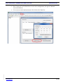
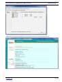
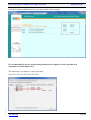
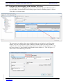
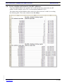
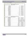
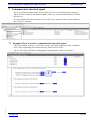
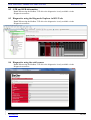
BCS Tools/Nexto - Modbus TCP and Crevis I/O KI00350 2013-08 1 Function and area of use This Start Up document describes the necessary steps to be taken when configuring Modbus TCP with Crevis I/O in a Nexto system. 2 About this Start Up document This Start Up document should not be considered as a complete manual. It is an aid to be able to start up a normal application quickly and easily. In this document the following software and hardware has been used. Software BCS Tools 1.31 Hardware Beijer Electronics NX3010 (CPU) Decentralized I/O (Crevis I/O) This document and other Start Up documents can be obtained from our homepage. Please use the address [email protected] for feedback on our Start Up documents. Page 1 (28) Beijer Electronics Automation AB a company in the Beijer Electronics Group Parent Company (Reg. office) Beijer Electronics Automation AB P.O. Box 426 SE-201 24 MALMÖ, SWEDEN Telephone +46 40 35 86 00 Fax +46 40 93 23 01 Visitor’s address Stora Varvsgatan 13A, Malmö Subsidiaries Norway, Drammen: Beijer Electronics AS, +47 32 24 30 00 Finland, Helsinki: Beijer Electronics Oy, +358 207 46 35 40 Denmark, Copenhagen: Beijer Electronics A/S, +45 70 26 46 46 Estonia, Tallin: Beijer Electronics Eesti Oü, +372 6 518140 Latvia, Riga: Beijer Electronics SIA, +371 7 842280 Lithuania, Vilnius: Beijer Electronics UAB, +370 5 2323101 Reg no. 556701-3965 VAT no SE556701-3965-01, Internet www.beijer.se, e-mail [email protected] BCS Tools/Nexto - Modbus TCP and Crevis I/O KI00350 2013-08 KI_eng.dot, 070221 3 Table of Contents 1 Function and area of use .................................................................................................................... 1 2 About this Start Up document ........................................................................................................... 1 3 Table of Contents ................................................................................................................................ 2 4 Overview .............................................................................................................................................. 3 5 Configuration in BCS Tools ............................................................................................................... 3 5.1 Create a new project ..................................................................................................................... 4 5.2 Configure the IP address of NET1 interface................................................................................. 7 5.3 Configure the IP address of NA-9189........................................................................................... 8 5.4 Add the Modbus Client device .................................................................................................... 10 5.5 Add the Modbus TCP slave......................................................................................................... 11 5.6 Data mapping in NA-9189 .......................................................................................................... 11 5.7 Configure the data mapping of the Modbus TCP slave.............................................................. 15 5.8 Create variables and connect to the IEC addresses ................................................................... 17 6 Compile and download of the project ............................................................................................ 19 6 Compile and download of the project ............................................................................................. 20 6.1 Compile of the project................................................................................................................. 20 6.2 Download of the project.............................................................................................................. 20 7 Communication interlock signal...................................................................................................... 24 7.1 Example of how to create a communication interlock signal ..................................................... 24 8 Troubleshooting ................................................................................................................................ 25 8.1 Diagnostic structures .................................................................................................................. 25 8.2 OTD and LED information ......................................................................................................... 28 8.3 Diagnostics using the Diagnostic Explorer in BCS Tools .......................................................... 28 8.4 Diagnostics using the web browser ............................................................................................ 28 www.beijer.se 2 (28) BCS Tools/Nexto - Modbus TCP and Crevis I/O KI00350 2013-08 4 Overview This is the basic configuration. The communication between the NX3010 and the NA-9189 uses the built-in ethernet port of the NX3010. KI_eng.dot, 070221 5 Configuration in BCS Tools www.beijer.se 3 (28) BCS Tools/Nexto - Modbus TCP and Crevis I/O KI00350 2013-08 5.1 Create a new project Create a new project from the File menu. Choose the path of where the project should be created and the standard template. KI_eng.dot, 070221 Choose the cpu, rack and power supply model. www.beijer.se 4 (28) BCS Tools/Nexto - Modbus TCP and Crevis I/O KI00350 2013-08 Choose the project profile, in this case the basic is being used. In the Basic project profile, the application has a user task from the Freewheeling type called MainTask which executes the program in a continuous loop (with no definition of cycle time) with priority fixed in 13. This task is responsible for the execution of a single programming unit POU called MainPrg. It is important to stress that the cycle time can vary according with communication task quantity used, as in this mode, the main task is interrupted by communication tasks. This profile allows the inclusion of two interruption tasks with higher priority which can preempt the MainTask at any moment: the task called ExternInterruptTask00 is an interruption task from the Extern type with priority fixed in 02; the task called TimeInterruptTask00 is an interruption task from the cyclic type with priority fixed in 1. KI_eng.dot, 070221 For details about the other profiles refer to the CPU User’s manual. www.beijer.se 5 (28) BCS Tools/Nexto - Modbus TCP and Crevis I/O KI00350 2013-08 Choose the prefered programming language for the freewheeling task. KI_eng.dot, 070221 Choose the prefered programming language for the interrupt tasks. www.beijer.se 6 (28) BCS Tools/Nexto - Modbus TCP and Crevis I/O KI00350 2013-08 5.2 Configure the IP address of NET1 interface When the wizard is completed the following view appears, this is where the hardware configuration of the system is made. In this start up we will use the following IP adresses: NX3010 = 10.101.221.52, NA9189_1 = 10.101.221.53, NA9189_2 = 10.101.221.54 KI_eng.dot, 070221 Double-click the NET1 icon in the project tree and enter the IP details of the NX3010. www.beijer.se 7 (28) BCS Tools/Nexto - Modbus TCP and Crevis I/O KI00350 2013-08 5.3 Configure the IP address of NA-9189 Factory settings IP-address 192.168.123.1 Subnet mask 255.255.255.0 Default Gateway 192.168.123.254 The addess can be changed in two ways. The basic way is by using ARP commands from the command promt. This is explained further down. The most intuitive way to change the addresses is to use the "Bootp server tool" in the software "IO Guide Pro", currently Windows XP is recommended to use. To setup using ARP commands follow these steps. Note! The IP can only be changed to another within the same subnet. Command Prompt >ping 192.168.123.236 //current IP address >arp -a //view Ethernet physical address >arp -d 192.168.123.236 //delete arp table >arp -s 192.168.123.237 00-14-F7-00-00-00 //assign static arp table with new IP address //”00-14-F7-00-00-00” is Ethernet Address (See Adapter Label) >ping -n 1 –l 741 192.168.123.237 //assign new IP address >arp -d * //clear all arp table >ping 192.168.123.237 //check response of adapter new IP address New IP-Address setup. IP Address = 192.168.123.237 Subnet Mask = 255.255.255.0 Gateway = 192.168.123.254 KI_eng.dot, 070221 To setup the IP address using IO Guide Pro follow these steps: Start IO Guide Pro In the "Tools" menu, select "Bootp server". Click the "Add New Device" button at the bottom. Enter the requested parameters. (the MAC address is printed on the node module) Click Ok, close down the Bootp tool, and try to ping the unit. Now you can create a new project in IO Guide Pro using the NA-9189 bus module. www.beijer.se 8 (28) KI_eng.dot, 070221 BCS Tools/Nexto - Modbus TCP and Crevis I/O KI00350 2013-08 Run "Autoscan" in IO Guide Pro to receive the configuration. (the green "antenna" icon sown belowe) You can now check and monitor the NA-9189 in IO Guide Pro. www.beijer.se 9 (28) BCS Tools/Nexto - Modbus TCP and Crevis I/O KI00350 2013-08 5.4 Add the Modbus Client device KI_eng.dot, 070221 The next step is to insert the Modbus TCP client device on the NET1 interface. This is done by right-clicking the NET1 port and choose Add device and select the Modbus Client device. www.beijer.se 10 (28) BCS Tools/Nexto - Modbus TCP and Crevis I/O KI00350 2013-08 5.5 Add the Modbus TCP slave To add the Modbus TCP slaves double-click the newly inserted device, Modbus_Client, then click the Add button and enter a name and the IP address of the slave. For further details about other settings refer to the cpu User’s manual. 5.6 Data mapping in NA-9189 KI_eng.dot, 070221 The NA-9189 module maps all data from/to the I/O modules mounted to one input and one output area. www.beijer.se 11 (28) BCS Tools/Nexto - Modbus TCP and Crevis I/O KI00350 2013-08 Input data is mapped as both holding register and coils and the same applies for the output data. The two NA-9189 used in this example are equipped with the following modules. NA-9189 | ST-3702 | ST-1218 | ST-2744 ST-3702 = 2 RTD inputs ST-1218 = 8 DI ST-2744 = 4 DO KI_eng.dot, 070221 The address mapping can be checked by using IO Guide Pro from the View menu and select the View address map option. www.beijer.se 12 (28) BCS Tools/Nexto - Modbus TCP and Crevis I/O KI00350 2013-08 KI_eng.dot, 070221 Another way to check the mapping is to use a web browser and connect to the NA-9189. www.beijer.se 13 (28) BCS Tools/Nexto - Modbus TCP and Crevis I/O KI00350 2013-08 Click the Expansion Module button to get more details of the mapping. It’s recommended to always install analog modules before digital to avoid a possible byte separation of a 16bit input word. The following is a example of a byte separation: KI_eng.dot, 070221 NA-9189 | ST-1218 | ST-3702 | ST-2744 www.beijer.se 14 (28) BCS Tools/Nexto - Modbus TCP and Crevis I/O KI00350 2013-08 5.7 Configure the data mapping of the Modbus TCP slave Click the Add button to configure how to access the NA-9189. The most efficient way is to use the Modbus function Read/Write Holding register, therefore Holding register is chosen. Click OK to verify the setting. KI_eng.dot, 070221 The next step is to configure how many holding register to read and write and from what address. The NA-9189 input area starts at address 0 and the output area starts at address 2048. The NA-9189 has 0-based addressing which means that the lowest address is 0, while the Nexto system is 1-based which means that the lowest address is 1. This will give us a offset with 1 when addressing a NA-9189. www.beijer.se 15 (28) BCS Tools/Nexto - Modbus TCP and Crevis I/O KI00350 2013-08 Function = Read/Write Slave address = Not used when using NA-9189, use default value Polling = Set the desired polling rate Mapping Diagnostics Area = This is the IEC adresses that will contain diagnostics about the mapping function, refer to Cpu User’s manual for more details. Read Settings Read Data Start Address = Starting address to read from NA-9189 (because of the address offset address 1 will be address 0 in NA-9189) Read Data Size = Number of Holding registers to read. Read IEC Variable = The IEC address to map the read Holding registers. Write Settings Write Data Start Address = Starting address to write in NA-9189 (because of the address offset address 2049 will be address 2048 in NA-9189) Write Data Size = Number of Holding registers to write. Write IEC Variable = The IEC address to map the written Holding registers. Repeat the mapping for the other NA-9189. The IEC addresses used for the other NA-9189 is: Read IEC Variable = 30040 Write IEC Variable = 30060 KI_eng.dot, 070221 The first NA-9189 only occupies from from 30000 – 30004 and 3020 – 3020 by creating some “space” between the addresses future expansion will be easier. The mapping is now complete. www.beijer.se 16 (28) BCS Tools/Nexto - Modbus TCP and Crevis I/O KI00350 2013-08 5.8 Create variables and connect to the IEC addresses To get the Modbus data in user variables the variable needs to be connected to the IEC address. In this example a new GVL is created named ModbusTCP_IO. KI_eng.dot, 070221 The relation between the Modbus adress in the NA-9189 to the user variable is according the following table. This is the relation for the NA-9189_1 www.beijer.se 17 (28) BCS Tools/Nexto - Modbus TCP and Crevis I/O KI00350 2013-08 KI_eng.dot, 070221 This is the relation for NA9189_2. www.beijer.se 18 (28) BCS Tools/Nexto - Modbus TCP and Crevis I/O KI00350 2013-08 Screenshot of the created varibles connected to the addresses above. KI_eng.dot, 070221 6 www.beijer.se 19 (28) BCS Tools/Nexto - Modbus TCP and Crevis I/O KI00350 2013-08 Compile and download of the project This chapter describes how to compile and download the project. 6.1 Compile of the project When the configuration has been completed the project has to be compiled. To compile the project click the menu Build\Generate code. Once the code generation has been successful it’s time to download the project. 6.2 Download of the project To download the project the accesspath to the cpu must be configured. The access must be made via the built-in ethernet port of the cpu. The default IP-adress of NET1 is 192.168.15.1 In case of using the NX3020 or NX3030 with two ethernet ports NET1 must be used for communication with BCS Tools. KI_eng.dot, 070221 Double-click the device in the project tree to access the communication settings. www.beijer.se 20 (28) BCS Tools/Nexto - Modbus TCP and Crevis I/O KI00350 2013-08 Choose the Scan Network option or add the device manually by clicking the Add device button. If the cpu is found on the network it will be shown in the list. If cpu is unavailable an error message will be shown. KI_eng.dot, 070221 When the cpu has been found click the button Set active path. The cpu in the list will be bold to indicate that this is the path that will be used when an online action is made. www.beijer.se 21 (28) BCS Tools/Nexto - Modbus TCP and Crevis I/O KI00350 2013-08 To download the project click the Login button and click the Yes button. If the cpu is empty or if there is another project running BCS Tools will prompt the user to confirm the download. The cpu will be stopped and the older project will be overwritten. The progress of the download can be found down in the left corner of BCS Tools. KI_eng.dot, 070221 When the download is completed the cpu is in STOP state. To set the cpu into RUN state press the run button. No reset or power on/off is necessary after the download even if parameters has been changed. www.beijer.se 22 (28) BCS Tools/Nexto - Modbus TCP and Crevis I/O KI00350 2013-08 The status of the cpu and the Modbus TCP driver can be found in BCS Tools. To see status of each slave the diagnostic variables must be used. KI_eng.dot, 070221 If a Modbus TCP slave is missing in the network this can be read by the diagnostic variable. www.beijer.se 23 (28) BCS Tools/Nexto - Modbus TCP and Crevis I/O KI00350 2013-08 7 Communication interlock signal For every module mounted in the Nexto system, BCS Tools creates diagnostic structures. These structures contains detailed information of the cpu, communication module, Profibus DP slave etc. For more details about these structures refer to the User’s manual of the specific module or the CPU User’s manual. 7.1 Example of how to create a communication interlock signal This is an example of how we can create a Comm_OK signal. When any of the configured slaves stops responding to the master this flag will be set to FALSE. KI_eng.dot, 070221 There is also flags available for independent communication control of each slave. www.beijer.se 24 (28) BCS Tools/Nexto - Modbus TCP and Crevis I/O KI00350 2013-08 8 Troubleshooting To troubleshoot and get diagnostics from the Nexto system there are several possibilities available. Diagnostics structures, created automaticly in BCS Tools. The OTD, One Touch Diagnostics function and LED:s. Diagnostics via the WWW page in the cpu. 8.1 Diagnostic structures KI_eng.dot, 070221 When the Modbus TCP driver is inserted a data structure is created automaticly located in a list named Diagnostics. This list will be populated with diagnostics structures for all hardware inserted in BCS Tools. www.beijer.se 25 (28) BCS Tools/Nexto - Modbus TCP and Crevis I/O KI00350 2013-08 The diagnostics variables DG_ModbusTCP_Communication.bRunning is a variable indicating that the ModbusTCP driver is running with no errors. The diagnostics variables DG_NA9189_1_Mapping_000.bCommOk is a variable indicating that the communication with the slave NA9189_1 is running with no errors. KI_eng.dot, 070221 The diagnostics variables DG_NA9189_2_Mapping_000.bCommOk is a variable indicating that the communication with the slave NA9189_2 is running with no errors. www.beijer.se 26 (28) BCS Tools/Nexto - Modbus TCP and Crevis I/O KI00350 2013-08 The following is an example when more data is accessed then available in NA9189_2. The diagnostics variables DG_NA9189_2_Mapping_000.bCommError is TRUE, the DG_NA9189_2_Mapping_000.eLastErrorCode is reporting ERR_EXCEPTION and the DG_NA9189_2_Mapping_000.eLastExceptionCode is reporting MAPPING_NOT_FOUND. When the error is present the DG_NA9189_2_Mapping_000.wCommErrorCounter will increment for every telegram sent to the slave. The diagnostics variables DG_NX5001.tMstStatus.abySlv_State.bSlave_xx are variables representing the online status of the configured slaves in the project. For example DG_NX5001.tMstStatus.abySlv_State.bSlave_3 is a Profibus DP slave with station number 3. The value TRUE = online and FALSE = offline. KI_eng.dot, 070221 For more information about the structures refer to the User’s manual of the cpu. www.beijer.se 27 (28) BCS Tools/Nexto - Modbus TCP and Crevis I/O KI00350 2013-08 8.2 OTD and LED information Note! When using the Modbus TCP driver the diagnostics is only available via the Diagnostic structures. 8.3 Diagnostics using the Diagnostic Explorer in BCS Tools Note! When using the Modbus TCP driver the diagnostics is only available via the Diagnostic structures. 8.4 Diagnostics using the web browser KI_eng.dot, 070221 Note! When using the Modbus TCP driver the diagnostics is only available via the Diagnostic structures. www.beijer.se 28 (28)