1
·m·
lwl
Interactive Microware, Inc.
P.O. Box 771
State College, Pa 16801
(814) 238-8294
ADA-AMP
INSTRUMENTATION AMPLIFIER
USER'S MANUAL
By Paul K. Warme
Copyright (c) 1983
INTERACTIVE MICROWARE, INC.
FEATURES OF THE ADA-AMP INSTRUMENTATION AMPLIFIER ••••••••••••
ADA-AMP Specifications •••••.••.•••••••••••••••••••••••••
ADA-AMP Opt ions. . . . . . . . . . . . . . . . . . . . . . . . . . . . . . . . . . . . . . . . .
1
1
MAKING CONNECTIONS TO ADA-AMP ••••••••••••••••••••••••••••••••
4
CALIBRATION ADJUSTMENTS OF ADA-AMP•••••••••••••••••••••••••••
6
PROGRAMMING ADA-AMP • • • • • • • • • • • • • • • • • • • • • • • • • • • • • • • • • • • • • • • • • •
7
~••••••••••••
8
HINTS ON REDUCING NOISE AND LOW PASS FILTERING •••••••••••••••
9
CALIBRATING ADA-AMP WITHOUT A VOLTMETER •••••••••
2
THE SOLID STATE TEMPERATURE SENSOR OPTION •••••••••••••••••••• 11
THE ADA-AMP BOARD WITH OPTIONS 1 AND 2A•••••••••••••••••••••• 12
-----------~------·-··----------·-------------
FEATURES OF THE APA-AMP INSTRUMENTATION AMPLIFIER
Interactive Microware•s ADA-AMP (tm) instrumentation
amplifier is a versatile signal conditioning accessory. ADA-AMP
facilitates interfacing scientific instruments to IMI's
ADALAB(tm) data acquisition/control interface for the APPLE II
computer. ADA-AMP can amplify voltage input signals as low as
+500 microvolts and can attenuate signals as high as +10 volts.
ADA-AMP's modular design allows you to equip the basic amplifier
with the operational features necessary for your specific
application, including programmable gain/attenuation and 8- to
16-channel differential multiplexers or 16- to 32-channel
single-ended multiplexers. ADA-AMP provides a cost-effective
approach to signal conditioning since it can be upgraded (at the
factory) to include options not specified at the time of initial
purchase. Key specifications and available options for ADA-AMP
are described below.
APA-AHP Specifications
IMI's ADALAB interface card to read full-scale
* Allows
voltages ranging from +500 microvolts to +10 volts.
*
High-quality instrumentation amplifier allows
switch-selectable gains of 0.1, 1, 10 and 100.
amplification is provided by an operational
* Additional
amplifier with variable gain from 1 to 10. Thus, the
overall gain is continuously adjustable from 0.1 to 1000.
*
Differential inputs offer high common mode rejection (70-100
dB) and high input impedance (8 megohms).
*
A low-pass filter smoothes high frequency noise.
time constant is 1 millisecond.
*
Includes 16-pin DIP sockets for input and output1 both
sockets are identical to ADALAB's analog cable.
The normal
terminal connections for D/A, A/D+, A/D- and ground are
* Pin
also provided, similar to IMI's Self-Test Adapter
terminals.
*
Mounted in plastic box 4-1/4" W x 7-1/2 8 L x 3-3/4 8 H.
* Optional programmable attenuation by a factor of 2, 4, 8,
16, 32, 64, 128, 256, 512 or 1024, selected by ADALAB's
digital output bits 4 through 7. This allows your programs
to select high gain for small input voltages and low gain
for large input voltages.
Apple is a registered trademark of Apple Computer, Inc.
ADALAB and ADA-AMP are trademarks of Interactive Microware, Inc.
ADA-AMP MANUAL...;2
*
Optional solid-s·tate multiplexer selects one of eight
differe tial inputs or orie of 16 single-ended inputs, under
control of bits 9 through 3 of ADALAB 1 s digital output.
The mul iplexer option includes convenient screw~terminal
connections for all input signals.
*
Optional expander caDd adds an additional eight differential
inputs or 16 single-ended inputs.
*
The basic ADA-AMP. Instrumentation Amplifier includes switch
selectable g ins of 9.1, 1.9, l9 ~nd 199 plus operational
amplifier wi h variable gain froml to 19, permitting overall
gain from 9.1 to.l999.
Option 1 :
Software Programmable Gain/Attenuation Module.
Option 2A:
8-Channel Differential Multiplexex Module.
Option 2B:
16-Channel Single-Ended Multiplexer Module
(Note: only one of Options 2A or 2B may be
selected, although you may change from Option 2A
to Options 2B, or from Option 2B to Option 2A
in the field by making one modification to the
printed circuit board and ordering the alternate
integrat·efd circuit 'from.· IMI for $25.)
Option 3A:
8-Channel Differential Input Expander (total of
16 channels) •
Option 3B:
16-Channel Single-Ended Expander (total of
32 c·hannels) ~
Option 4
Solid-State Temperature Sensor for Cold Junction
Compensation of Thermocouples, 9 to 299
uV/degree C, with 6-foot cable, factory
installed on input channel 9.
Option 5
9-Volt Battery Power Supply for remote signal
amplification. This is recommended when signal
wires are longer than 5 feet. Batteries included.
Operating voltage is limited to ±6 Volts. This
option is not recommended when the multiplexer or
programmable gain options are used, because the
digital output cable would also need to be
extended in this case.
ADA-AMP MANUAL-3
Option 6
12" Cable (16-conductor) with DIP headers on each
end for connecting ADA-AMP to ADA-MUX (1 required)
or for chaining ADA-MUX modules (2 required).
*Options listed may be installed retroactively at the factory for
a modest additional charge.
ADA-AMP MANUAL-4
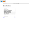
As you r ad this section, you should identify the various
parts in the iagram on the last page of this manual or on the
ADA-AMP inter ace module.
The ANAL G OUT socket on ADA-AMP is connected to ADALAB via
the 16-conduc or ANALOG cable, which carries power to ADA-AMP and
also routes a alog voltages to the A/D and D/A converters on
ADALAB. If t e multiplexer and/or programmable attenuator
options have een installed on your ADA-AMP, you will also need
to connect AD LAB's OUTPUT cable to the DIGITAL OUT socket on
ADA-AMP. If ou are using ADA-AMP with an ADA-MUX multiplexer,
connect ADALA 's OUTPUT cable to the HEADER socket on ADA-MUX and
also connect
short (12n) cable between one of the two ANALOG
sockets on AD -MUX to the ANALOG IN socket on ADA-AMP. When
making these able connections, be sure to connect pin 1 on the
socket (bevelled corner marked white) to pin 1 of the cable
(marked white) •
On the 1 ft side of the ANALOG IN socket, you will note two
columns of four terminals labelled D (forD/A), H (for High, or
A/D+), L (for LOW, or A/D-) and G (for Ground). The left-hand
column of terminals is used only for the multiplexer options. As
shipped, two jumpers are installed on the right-hand column to
connect H to D and L to G, 'just like the Self-Test Adapter. This
configuratio is useful for testing purposes; you may output a
voltage on
ALAB's D/A converter and read the amplified voltage
on the A/D c nverter. On the right side of the ANALOG IN socket
is a 19 Kohm potentiometer (DA GAIN), which is used as a voltage
divider to a tenuate the D/A output voltage. If you wish to
adjust the D A gain, you should output the full-scale D/A voltage
(set D%=2947: &A00), attach your voltmeter to pins D and G and
turn the DA AIN pot to yield the desired input voltage to the
amplifier.
There a
to ADA-AMP.
the two jump
connect your
Alternative!
and connect
Another way
socket, whic
e several ways to connect external voltage signals
Before connecting external signals you ~ remove
rs connecting D to H and L to G. Then, you may
input voltage directly to the H and L terminals.
, you may insert a #22 wire in one side of a jumper
he other side of the jumper to a terminal pin.
o cor.nect signals to ADA-AMP is via the ANALOG IN
has the same pinout as ADALAB's ANALOG socket:
s 1 - 9 = Digital Ground
10
= A/D+ (high)
11
= Analog Ground
12
= A/D- (low)
13
= D/A+ {high)
14
= -12 Volts
15
= +12 Volts
16
= Digital Ground
ADA-AMP MANUAL-S
You may solder wires or components to the 16-pin DIP header,
which is plugged into the ANALOG IN socket. (Additional headers
are available from IMI}.
If the a-channel multiplexer option has been installed on
your ADA-AMP, connections will be made to the screw-terminal
barrier strip, where you will find the high (H) and low (L}
inputs side-by-side for each channel numbered from 8 to 7. The
terminal labelled DA carries the D/A output voltage, and the
terminal labelled AG is analog ground. (For the 16-channel
single-ended multiplexer, the low (L} terminals are used for
channels 8 to 7 and the high (H) terminals are used for channels
8 to 15; all signals share a common ground which must be
connected to the rightmost screw terminal labelled AG.} If you
have purchased the multiplexer expander card, the remaining
inputs are on the terminal strip on the piggyback board.
IMPORTANT:
CAUTION:
When using the multiplexer, BE SURE to remove the
jumper connecting D to H before connecting any
inputs to the screw terminals. For ~he
differential multiplexer, turn the jumpers 98
degrees on both terminals H and L; this connects
the multiplexer outputs to the amplifier. For
the single-ended multiplexer, turn only the
jumper on terminal H by 98 degrees and connect a
jumper between terminals L and G (not turned
98 degrees} •
DO NOT apply a voltage to ADA-AMP which exceeds
+12 volts; otherwise, permanent damage may
result and the 98-day warranty is voided.
The output voltage from ADA-AMP saturates at
about +18 volts. Although ADALAB can only read
voltages up to +4 volts, it will not be harmed
by voltages less than +12 volts.
ADA-AMP MANUAL-6
p
You shou d always allow at least 15 minutes warmup time for
the ADALAB in erface card and ADA-AMP before calibrating the
amplifier. F"rst, select the primary gain of the instrumentation
amplifier by urning on only one of the four GAIN switches marked
~.1, 1, 1~ or 1~~.
The gain selection switches are ON when the
button is dow on the side marked ~.1, 1, 1~ or 1~~. For slide
switch models, the switch is ON when the knob is closest to the
number labels.
The foll
an input impe
you do not ha
the IZ zero p
pre-adjusted
amplifier as
ADA-AMP WITHO
adjustment procedure requires a voltmeter with
ance of at least 1 megohm or an oscilloscope. If
e access to either of these, you should not change
t or the AZ zero pot; these pots have been
t the factory. Instead, you should calibrate the
escribed in the section entitled "CALIBRATING
T A VOLTMETER" •
Remove a
wires) and in
between the g
the center of
instrumentati
voltmeter rea
is installed,
and adjust th
zero reading
the test pin
(marked OZ) f
y inputs to terminals H or L (sockets, jumpers or
tall a jumper from H to L. Attach a voltmeter
ound (G) terminal and the test pin marked IA near
the ADA-AMP interface card. Adjust the
n amplifier zero pot (marked IZ) until the
ing is zero. If the programmable attenuator option
next attach the voltmeter to the test pin marked AA
attenuation amplifier zero pot (marked AZ) for a
n the voltmeter. Finally, attach the voltmeter to
arked OA and adjust the output amplifier zero pot
r a zero reading.
Now, rem ve the jumper between H and L and apply the desired
full-scale in ut voltage to the ADA-AMP input terminals labelled
H and L. Adj st the output amplifier gain pot (marked OG) to
give a voltag at test point OA that is somewhat less than the
range selecte by the jumpers on ADALAB (±~.5, 1, 2 or 4 Volts).
An easy way t apply a voltage for calibration purposes is to use
ADALAB's D/A oltage output by connecting jumpers from D to H and
from L to G o ADA-AMP's input terminals. For example, to output
the full-seal D/A voltage, type D%=2047: &AO~. Of course,
QUICKI/0 must first be initialized by RUNning QUICKSAMPLE or by
BRUNning QUIC I/Oe When the amplifier is set for high gain, it
is necessary to adjust the D/A gain pot so that after
amplification, the output voltage remains within the voltage
range of ADAL B's A/D INPUT.
ADA-AMP MANUAL-7
PROGRAMMING ADA-AMP
In its simplest configuration, without the multiplexer and
programmable attenuator options, no special programming is
needed. You simply attach your external voltage signal to
ADA-AMP and read the amplified voltage via ADALAB's ANALOG cable
in the normal way, using the &AIB command in QUICKI/0.
The multiplexer is controlled by the least significant four
bits of ADALAB's digital OUTPUT. Channels B to 15 are selected
by setting the appropriate binary pattern in the low bits. For
example, to select channel 2, you would set D%=2 and issue the
&POB command. (If you have purchased the 32-channel single-ended
expander version, digital OUTPUT bit 7 selects either channels B
to 15 (bit 7 off) or channels 16 to 31 (bit 7 on); also, only
attenuation values B through 7 are available.)
The programmable attenuator is controlled by the most
significant four bits of ADALAB's digital OUTPUT. Attenuation
factors from 2 to 1924 are calculated by multiplying 16 times a
number from B to 9 and adding the channel number. In other
words, the series of values B, 16, 32, 48, 64, 89, 96, 112, 128,
144 will yield attenuation factors of 2, 4, 8, 16, 32, 64, 128,
256, 512, and 1924, respectively. For example, D%=16+1: &POB
will read channel 1 with an attenuation factor of 4. Notice that
as the digital OUTPUT value increases, the attenuation increases,
whereas the effective gain decreases. The minimum attenuation
factor is 2; therefore, the gain range of the output amplifier
has been increased to allow gains from 1 to 29. Thus, the
overall gain range is the same as that of ADA-AMP without the
programmable gain option.
Here is a sample program that will enable you to read any
channel with any desired attenuation factor. The input voltage
is assumed to come from the D/A converter (jumper D to H and L to
G) •
1
2
3
4
5
19
29
39
49
59
69
HIMEM:36995: D%=9: PRINT CHR$(4)"BRUN QUICKI/0"
POKE 36273,9 (disable parallel handshake)
POKE 36259,1 (enable analog handshake)
INPUT aADALAB VOLTAGE RANGE (9.5, 1, 2 OR 4) ?":FS
INPUT aD/A OUTPUT (-2947:2947) ?•:D%: &AOB
INPUT •cHANNEL # (9:15) ?";CH
INPUT "ATTENUATION FACTOR (9:9) ?";GN
D%=CH+GN*l6: &POB
&AIB (throw away first reading)
&AIB: PRINT "READING ="D%:TAB(29)"VOLTAGE = "D%/2947*FS
GOTO 5
Note that the first reading after changing the channel or
gain must be discarded because the amplifier output is inaccurate
for a short time while it adjusts to the new input voltage. If
your ADA-AMP does not have the multiplexer or programmable
attenuator option, you should omit lines 19 or 29, respectively,
ADA-AMP MANUAL-S
and modify li e 30 if necessary. To repeatedly read and print
the voltage u til any key is pressed, insert this line:
55 IF PEEK(-16384) < 128 GOTO 50
If you don't have a reliable voltmeter, you should leave the
IZ zero pot and the AZ zero pot in their factory-adjusted
positions. However, it is easy to adjust the overall gain and
offset of AD -AMP by using ADALAB as your voltmeter and voltage
source. The sample program listed under "PROGRAMMING ADA-AMP"
will be used for this purpose. First, select the gain (0.1, 1,
10 or 100) of the instrumentation amplifier as described in the
section called "CALIBRATION ADJUSTMENTS OF ADA-AMP." Then, RUN
the sample program (including line 55, which will continuously
update the readings on the screen) • Enter 0 as the value for D/A
OUTPUT and a just the OZ zero pot to give a zero reading on the
screen. Pre s the space key to continue on. Next, enter 2 as
the D/A OUTP T and turn the DA gain pot in the direction that
increases th reading on the screen. Turn this pot until the
reading no 1 nger increases~ this means that the D/A output
voltage is n w unattenuated by the DA gain pot. We can now
calculate th actual voltage of the D/A, based on the voltage
range of the D/A jumper on the ADALAB card. (We will assume that
the A/D jump rs on ADALAB are set for the same range as the D/A
jumper). For example, if the D/A jumper is set for the ±1 volt
range, then he output voltage will be 1 Volt if we enter 2047 as
the value of D/A OUTPUT. The final calibration step involves
adjusting th OG gain pot on ADA-AMP to give an appropriate
reading for
known D/A output voltage. For instance, to obtain
an overall g in of 100, enter 20 as the D/A OUTPUT value and
adjust the 0 gain pot to yield a reading of 2000 (or 20 * 100)
on the scree • This completes the calibration procedure.
If you ish to adjust the gain of the amplifier to a very
high value, "t is desirable to attenuate the D/A gain so that a
finer gradat"on of D/A values may be applied to the amplifier.
In order to djust the DA gain pot, select a D/A OUTPUT value
that produce an A/D reading of 2000 (as close as possible) on
the screen. Then, turn the DA gain pot to reduce the reading to
the desired ttenuated level. For example, to divide the D/A
voltage by 1 , you should turn the DA gain pot until the reading
on the scree is reduced from 2000 to 200 (or 2000/10).
ADA-AMP MANUAL-9
HINTS ON REDUCING NOISE AND LOW PASS FILTERING
Unfortunately, when external signals are amplified, the
noise is amplified along with the signal. Noise can cause big
problems when very large gains are used. Here are some
suggestions for minimizing noise:
1. Keep the signal cables from your instrument to ADA-AMP as
short as possible. Cables pick up induced noise from their
surroundings.
2. Avoid use of ribbon cables to carry analog signals. Twist
the two signal wires around each other so that any induced
noise will be the same for both wires1 the instrumentation
amplifier rejects noise which is equal on both the high and
low signals.
3. Use a shielded two-conductor cable to carry signals from
your instrument to ADA-AMP. The outer shield should be
connected either to the signal ground of your instrument or
to the ground terminal on ADA-AMP (the shield should be
connected to one end or the other, but not to both ends).
4. If your istrument has a 3-prong AC line cord, connect a wire
from the chassis of your instrument to the case of the
APPLE computer's power supply. This equalizes the ground
potential. Another way to accomplish this is to plug your
APPLE computer into the same electrical outlet that is used
for your instrument.
5. The input resistance (impedance) of ADA-AMP is very high
(8.2 megohm). High input resistance makes signal wires act
as antennas that can readily pick up noise. If the output
resistance of your instrument is lower than lOK ohms (as is
the case for most instruments), it is desirable to decrease
the input resistance of ADA-AMP. You can do this by
replacing the input resistors to ground from both the H and
L terminals of ADA-AMP (these are currently 8.2 megohm
resistors with gray, red and green stripes, located between
the GAIN switches and the AD521 chip). The appropriate
value for input resistance depends entirely upon the output
impedance (drive capability) of your external equipment1 if
the applied 1oltage decreases significantly when grounded
through the input resistor, then you should increase the
input resistance.
A quick way to check the effect of reducing the input
resistance is to connect a resistor between the H terminal
of ADA-AMP and the G terminal and also from the L terminal
to the G terminal. Normally, the input resistance should
be at least 10 K ohms1 some instruments may be damaged if
the input resistance is too low or if their signal leads
are shorted together.
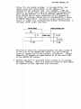
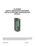
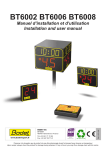
6. The ADA-AMP board includes a provision for adding a low pass
ADA-AMP MANUAL-10
filter or its output voltage. A low pass filter can
reduce oise very effectively, at the expense of
lengthe ing the response ~ime. For example, a 20K ohm
resisto in series with a 0.5 uF capacitor to ground will
yield a time constant of 10 milliseconds (20E3*0.5E-6).
Since A ALAB has an input resistance of 8.2 megohms to
ground, the voltage reading will be attenuated by a factor
of 20E3 8.2E6=2.44E-3. Of course, larger resistors will
result 'n longer time constants and greater attenuation. A
low pas filter looks like this:
ADA-1¥1P MODULE
tm
H ~>
ADALAB INTERFACE
I
CARD
)>---.----
DC
!RIBBON CABLEI
L ~~~--._----~>
>r-;-~~-8.2 M!l
-
(H)
Resisto OR should be installed between the pads marked OR
to the eft of the ANALOG OUT socket (cut the existing
trace o replace the 47 ohm resistor if present). Install
capac it r OC between the pads marked OC on the other side
of the NALOG OUT socket.
7. Another approach to smoothing noisy signals is to average
multipl readings. This is a practical solution when speed
of resp nse is less important than accuracy.
ADA-AMP MANUAL-11
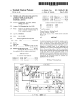
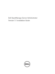
THE SOLID STATE TEMPERATURE SENSOR OPTION
If the solid-state temperature sensor (Option 4) has been
installed on your ADA-AMP, there will be two groups of four
terminal pins labelled 1 to 4 and 5 to 8. Jumpers on pins 2 to 3
and 6 to 7 will disconnect the temperature sensor from
multiplexer channel ~. To connect the temperature sensor to
channel ~' install jumpers from 1 to 2, 3 to 4, 5 to 6, and 7 to
8. See the addendum called "Notes on the Use of Solid State
Temperature Sensors" and the TEMPSENSE Manual for details on
calibration and use.
D = D/A HIGH
MUX HIGH [ ] H =AID HIGH
MUX LW
L = AID LCW
6
I
=GRO~D
H'IHLUU
u• - • '"'" • .. ~ "·- ·- · ·
TEMP SELECT
JlttPERS
GROLND POINT
-l
:c
m
• , r ; n"JW'rnr
1
.1>
1
-
lll•tnun1
~
. qrr
IIIIP
PW!LOG OUT = TO AOALAB CARD
~
~
tltl
~
!:
-1
:c
0
~
:z-
(1':1
~
"'"-
0
N
»
BIT8 BIT2 81T4 BIT6 IJ-.IDIJ-.!0 IJ-.IDIJ-.!0 -
1
2
3
4
5
6
7
B
0
o 16 - BITt
0
15
o 14
o 13
0 12
0 11
o 18
9
0
0
0
0
0
0
0
0
-
81T3
BITS
BIT?
+5V
+5V
CAl
CA2
OZ ZERO
pofj
OJ GITAL
DIGITAL
DIGITAL
DIGITAL
DIGITAL
DIGITAL
DIGITAL
DIGITAL
~D
~D
G-10
IJ-.!0
IJ-.!0
IJ-.ID
~D
IJ-.ID
-
1
2
3
4
5
6
0
o 16 - DIGITAL
0
15
0 14
0 13
o 12
o 11
o 18
0
9
0
0
0
0
7
I)
8
0
0
-
~D
+12V
-12V
0/A OUT
AID Llltl INPUT
~LOG IJ-.!0
AID HIGH INPUT
DIGITAL IJ-.ID
,..:1>'
t::l
I
:1>'
::::
"d
~
zd""
:1>'
~
I
~
"-'