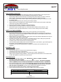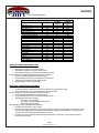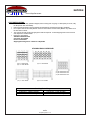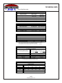
1
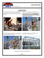
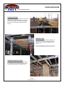
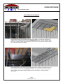
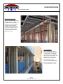
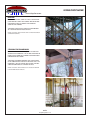
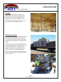
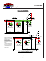
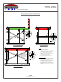
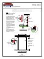
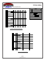
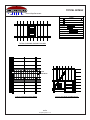
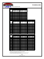
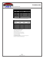
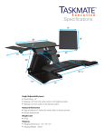
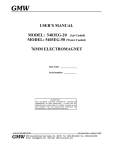
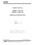
www.dropshore.com DROPSHORE SHORING SYSTEM USER MANUAL USING DROPSHORE www.dropshore.com SETTING DROPSHORE SET DROPHEAD TO LOCKED POSTION WITH A HAMMER BLOW TO THE LOCKING NUT. ADJUST POST SHORE TO PROPER PIN HOLE POSITION AND SPIN ADJUSTMENT NUT TO APPROXIMATE HEIGHT POSITION. START BY SETTING 4 POSTS IN A BOX USING TRIPODS FOR SUPPORT. USE LUMBER WEDGE CLAMPS TO DIAGONALLY BRACE POST SHORES IN TWO DIRECTIONS. SET THE MAIN BEAMS BY ENGAGING ONE END OF THE BEAM ON THE DROPHEAD OF THE SET POST, THEN ENGAGE THE OTHER END OF THE BEAM ON THE DROPHEAD OF THE POST BEING SET. AS MAIN BEAMS ARE SET IN PARALLEL ROWS, SET THE SECONDARY BEAMS TO THE APPROPRIATE SPACING. THE FRAMING IS NOW READY TO BE DECKED WITH PLYWOOD. AFTER AREAS ARE FRAMED UP AND ADEQUATELY BRACED PLYWOOD DECKING IS READY TO BE APPLIED. PLEASE REFER TO THE SAFETY SECTION FOR ADDITIONAL INFORMATION REGARDING THE SAFE AND PROPER USEAGE OF THE POST SHORES AND BEAMS. 1 of 6 Dropshore System r -1-10 USING DROPSHORE www.dropshore.com PLYWOOD DECKING A UNIT OF PLYWOOD CAN BE CAREFULLY PLACED ON SHORING THAT IS PROPERLY BRACED. INDIVIDUAL SHEETS CAN THEN BE PLACED AND A FEW 6 PENNY NAILS ARE USED TO SECURE PLYWOOD TO BEAM NAILERS. LUMBER FILLERS USE 4X4 LUMBER TO FILL IN SPACES WHERE A STD BEAM WILL NOT FIT. THE LEDGER OF THE MAIN BEAM WHERE THE LUMBER IS SUPPORTED IS SET DOWN 3-1/2”. REFER TO THE STD. DRAWING AND SAFETY SECTIONS FOR MORE INFORMATION REGARDING SAFE USEAGE OF LUMBER FILLERS. SHORING AROUND COLUMNS SHORE AROUND COLUMNS AND OTHER OBSTACLES BY ‘STRADDLING’ THE COLUMN WITH MAIN BEAMS AND BRIDGING THE GAP WITH LUMBER FILLERS. 2 of 6 Dropshore System r -1-10 USING DROPSHORE www.dropshore.com ADJUSTING RUNS OF SHORING WHEN ENCOUNTERING A WALL PERPENDICULAR TO THE MAIN BEAMS, ADJUSTING THE LENGTH OF THE SHORING IS EASILY ACCOMPLISHED USING THE ‘TURN AND SLIDE’ METHOD. STOP THE SHORING SHORT OF THE WALL, TURN MAIN BEAMS TO RUN PARALLEL TO THE WALL AND SLIDE THE MAIN BEAMS UP TO THE WALL. YOU HAVE INFINATE ADJUSTMENT. WHEN ENCOUNTERING A WALL PARALLEL WITH THE MAIN BEAMS, ADJUSTING THE SHORING LATERALLY IS EASILY ACCOMPLISHED USING THE ‘FINGERING-IN’ METHOD. AT THE OBSRTUCTION TURN MAIN BEAMS TO RUN PERPENDICULAR TO THE OBSTRUCTION AND SLIDE UP TO THE WALL. YOU HAVE INFINATE ADJUSTMENT. 3 of 6 Dropshore System r -1-10 USING DROPSHORE www.dropshore.com ELEVATION CHANGES BECAUSE THE ‘FRAMEWORK’ OF THE SHORING IS ‘OPEN’, SLAB ELEVATION CHANGES ARE EASILY ACCOMPLISHED BY LAPPING THE LOWER SHORING UNDER THE HIGHER SHORING. THE POST SHORES FOR THE HIGHER ELEVATION CAN PASS THROUGH THE LOWER SHORING. THIS CANNOT BE DONE WITH A PANALIZED SYSTEM. CALTILEVERING CANTILEVERING A WALKWAY IS TYPICALLY DONE WITH THE LONGER 11-6 MAIN BEAMS. THE LONGER MAIN BEAM CAN BE CANTILEVERED TO 30 IN. PAST THE SLAB EDGE. THE INBOARD END OF THE BEAM IS SECURED WITH A SAFETY CATCH, WHILE A GUARDRAIL POST ATTACHES TO THE OUTBOARD END. REFER TO THE SAFETY SECTION FOR MORE INFORMATION REGARDING SAFE USEAGE. 4 of 6 Dropshore System r -1-10 USING DROPSHORE www.dropshore.com BRACING BRACING FOR LATERAL STABILITY IS EASILY SET WITH THE USE OF WEDGE CLAMPS AND LUMBER. BRACING IN TWO DIRECTIONS ESPECIALLY AROUND THE PERIMETER STABILIZES THE SHORING. THE WEDGE CLAMPS CAN ALSO BE USED FOR HORIZONTAL LACING TO INCREASE POST CAPACITY. REFER TO THE SAFETY SECTION AND STD. DETAIL FOR MORE INFORMATION ON BRACING PROCEDURES. STRIPPING THE FRAMEWORK TO STRIP THE ALUMINUM BEAMS, STRIKE THE LOCK NUT TO RELEASE THE DROPHEAD. THIS ALLOWS THE BEAMS TO DROP 4 INCHES FROM THE PLYWOOD DECKING WITHOUT LOWERING THE POST SHORE. THE BEAMS CAN NOW BE REMOVED AND STACKED BACK IN THE STORAGE RACKS FOR USE AT THE NEXT LEVEL. THE DROPHEAD IS THE KEY FEATURE THAT ALLOWS THE POST SHORE TO CONTINUOUSLY SUPPORT THE DECK. REFER TO THE SAFETY SECTION AND CONSULT A STRUCTURAL ENGINEER FOR EARLY BEAM REMOVAL APPROVAL. 5 of 6 Dropshore System r -1-10 USING DROPSHORE www.dropshore.com RESHORE WITH THE ALUMINUM BEAMS STRIPPED AND MOVED TO THE NEXT POUR, THE UNDISTURBED POSTS ARE LEFT IN PLACE AS RESHORE. THIS ALLOWS FOR FAST AND SAFE POURING CYCLES. REFER TO THE SAFETY SECTION AND CONSULT WITH A STRUCTURAL ENGINEER FOR SAFE RESHORE PROCEDURES. MATERIAL HANDLING ALL DROPSHORE MATERIAL IS STORED AND SHIPPED IN STACKING RACKS FOR MAXIMUM EFFICIENCY. THE STACKING RACKS CAN EASILY BE CONVERTED INTO BOXES FOR STORAGE OF THE SMALLER ACCESSORIES. STORAGE, TRUCK LOADING AND JOBSITE HANDELING ARE SIMPLIFIED WITH THE STACKING RACK, AS THEY CAN BE MOVED WITH A FORKTRUCK OR CRANE. ONCE ONSITE, CASTER WHEELS CAN BE ADDED TO THE RACKS FOR ADDED MOBILITY. REFER TO THE SAFETY SECTION AND SHIPPING SECTION FOR MORE INFORMATION REGARDING SAFE USEAGE AND STANDARD RACKING PROCEDURES. 6 of 6 Dropshore System r -1-10 TYPICAL DETAILS www.dropshore.com "M IN -P ER OS H A TYPICAL CANTILEVER DETAIL 2'-6" MAX. WALKWAY 39 STEP 1 STEP 2 ERECT AND ERECT AND SECURE INT. SECURE CANT. FRAMING FRAMING 24" MAX SLAB CANTILEVER 11'-6" MAIN BEAM CANTILEVER BRACKET AT TRANSVERSE MAIN BEAM 5'-11" MAX. 6" MIN. ER OS HA 5'-11" TYP. USE POSITIONER AT ALL SUPPLEMENTAL SHORE LOCATIONS CANTILEVER BRACKET AT POST SHORE TYP. 1. EXTRA CAUTION MUST BE EXERCISED AT CANTILEVERED CONDITIONS TO AVOID FALL HAZARDS. WARN ALL PERSONNEL ON JOBSITE TO STAY OFF CANTILEVERED AREAS UNTIL INSTALLATION AND FALL PROTECTION IS COMPLETE. 39" STEP 1 STEP 2 ERECT AND ERECT AND SECURE INT. SECURE CANT. FRAMING FRAMING NOTES: MIN -P TYPICAL CANTILEVERED PERIMETER W/ 11'-6" MAIN BEAM 24" MAX. WALKWAY 5'-7" MAIN BEAM 2. AVOID LOADING CANTILEVERED MAIN BEAM PRIOR TO INSTALLING ALL SECONDARY BEAMS, POST SHORES, POSITIONERS, SAFETY CATCHES, CROSS BRACING, LACING AND ADJECENT PLYWOOD. 3. AVOID CANTILEVERING MAIN BEAMS WHERE ADJACENT FRAMING/PLYWOOD IS NOT SUFFICIENT TO BALLAST LOADS AT CANTILEVER. 4. AVOID POST SHORES UNDER MAIN BEAMS WITHOUT POSITIONERS. CANTILEVER BRACKET AT TRANSVERSE MAIN BEAM USE POSITIONER AT ALL SUPPLEMENTAL SHORE LOCATIONS CANTILEVER BRACKET AT POST SHORE TYP. 5. AVOID LOADING CANTILEVER BEYOND ITS DESIGN CAPACITY. 5'-11" TYP. 39" MAX. TYPICAL CANTILEVERED PERIMETER W/ 5'-7" MAIN BEAM 1 of 5 Dropshore System r -1-10 6" MIN. TYPICAL DETAILS www.dropshore.com TYPICAL BRACING AND LACING DETAIL BLOCK AND NAIL BRACE AT INTERSECTION WEDGE CLAMP LOCATION WEDGE CLAMP LOCATION TYPICAL LACING DETAIL TYPICAL PERIMETER BRACING NOTES: FULL HEIGHT 1. NOTE: IF ONE ONLY ONE CROSSBRACE IS ENGAGED BY THE CENTER WEDGE THEN NAIL UNCLAMPED BRACE TO CLAMPED BRACE USE 2X4 LUMBER FOR BRACING. 2. CROSS BRACES MUST SPAN AT LEAST 3 POST SHORES. 3. CROSS BRACES MUST BE INSTALLED FULL HEIGHT TOP OF ONE SHORE TO BOTTOM OF OTHER. 4. CROSS BRACES MUST BE SECURED WITH WEDGE CLAMPS AT ALL INDICATED LOCATIONS. 5. SEE LACING DETAIL FOR POST SHORE LACING. CROSS BRACE GUIDELINES: WEDGE CLAMP LOCATION TYPICAL INTERIOR BRACING 2 of 5 Dropshore System r -1-10 1. SET CROSSBRACING AT ALL EXTERIOR AND INTERIOR POUR BOUNDARIES, THE PERIMETER OF LOADING AREAS, AND ALL BEAM LOCATIONS. 2. CROSSBRACING MUST BE SET EVERY OTHER ROW OF SHORES IN BOTH DIRECTIONS AT A MINIMUM. 3. CROSSBRACING ALONG WALL IS NOT A REQUIREMENT. 4. ADDITIONAL CROSSBRACING IS REQUIRED ON SLOPES AND RAMPS. TYPICAL DETAILS www.dropshore.com TYPICAL SAFETY POST AND LUMBER FILLER BEAM DETAIL NOTES: 1. PRECAUTIONS MUST BE TAKEN WHILE INSTALLING SAFETY POST AND GUARDRAIL TO PREVENT FALL HAZARDS. STEP 1 STEP 2 ERECT AND ERECT AND SECURE ALL SECURE FRAMING AND SAFETY POST DECKING AND GUARDRAIL SAFETY POSTS AT 8' OC MAX. MIN PE RO SH A 2. NO PERSONNEL ALLOWED ON DECK UNTIL SHORING INSTALLATION AND FALL PROTECTION IS COMPLETE AND NAIL GUARDRAIL INSPECTED BY A SAFETY MANAGER. TO SAFETY COMPLETE SHORING INSTALLATION POST POCKET INCLUDES ALL NECESSARY CROSS BRACING/LACING, SAFETY CATCHES, POST SHORES AND POSITIONERS, AND DECKING. 39" 3. SAFETY POSTS MUST NOT EXCEED 8' OC SPACING. SAFETY POSTS MUST BE FULLY SEATED INTO MAIN BEAM END CAP AND NAILED TO DECKING / MAIN BEAM TO PREVENT UPLIFT. LAP 2X4 GUARDRAILS AT SAFETY POST 4. GUARDRAILS MUST BE MADE FROM 2X4'S. GUARDRAILS MUST BE SECURED TO SAFETY POST POCKETS WITH NAILS. LAPPING OF 2X4'S MUST TAKE PLACE AT THE SAFETY POST. 5. ALL WALKWAY AREAS MUST BE DECKED AND HAVE FALL PROTECTION INSTALLED. 6. IN THE EVENT THAT DROPSHORE SAFETY POSTS CANNOT BE USED BECAUSE OF JOB CONDITIONS, PROPER OSHA APPROVED FALL PROTECTION MUST BE INSTALLED AND USED BY CONTRACTOR. GUARDRAIL SAFETY POST NAIL SAFETY POST TO DECK/MAIN BEAM 5'-1" 4'-9" MAX NOTES: 1. USE STRUC. 1 4X4'S OR MICROLAM. 2. ENSURE TIGHT FIT BY CUTTING LUMBER TO MATCH ANGLES OF SUPPORTING BEAMS. SECURE LUMBER WITH 2 - #16 DUPLEX NAILS EACH END 3. USE TYPICAL SECONDARY BEAM SPACING. LUMBER FILLER BEAM DETAIL 4. SECURE THE LUMBER FILLER BEAM WITH 2 - #16 DUPLEX NAILS AT EACH END. TYPICAL LUMBER FILLER BEAM 3 of 5 Dropshore System r -1-10 TYPICAL DETAILS www.dropshore.com LEGEND #3 PROP LOW PROP W/ POSITIONER #4 PROP #5 PROP 11'-6" MAIN BEAM 5'-7" MAIN BEAM 3'-9" MAIN BEAM 5'-7" SECONDARY BEAM WOOD FILLER NOTE: GRAYED OUT BEAMS AND POSTS ARE AT LOWER ELEVATION THAN TYPICAL DECK. SAFETY CATCHES POSITIONER TYPICAL TURN AND SLIDE DETAIL TYPICAL FINGER-IN DETAIL 4 of 5 Dropshore System r -1-10 (AT ALL CANTILEVER CONDITIONS) (AT ALL SUPPLEMENTAL SHORE LOCATIONS) TYPICAL DETAILS www.dropshore.com LEGEND #3 PROP LOW PROP W/ POSITIONER #4 PROP #5 PROP 11'-6" MAIN BEAM 5'-7" MAIN BEAM 3'-9" MAIN BEAM 5'-7" SECONDARY BEAM WOOD FILLER NOTE: GRAYED OUT BEAMS AND POSTS ARE AT LOWER ELEVATION THAN TYPICAL DECK. SAFETY CATCHES POSITIONER (AT ALL CANTILEVER CONDITIONS) (AT ALL SUPPLEMENTAL SHORE LOCATIONS) TYPICAL SHORING AROUND COLUMN LOW SHORING TYPICAL OUTSIDE CORNER DETAIL TYPICAL SHORING UNDER BEAM 5 of 5 Dropshore System r -1-10 SAFETY www.dropshore.com POST SHORES: • • • • • • • • Post shores must be installed completely vertical, use level to verify. Cross bracing must be installed as shores and framing are being erected. Post shores used as reshoring must be secured by using spring clips, cross-bracing or other appropriate methods to prevent a falling material hazard. Special precautions must be taken when shoring off of, or up to a sloping surface. o Additional cross braces must be installed to stabilize framing. o Lumber wedges must be installed under the base plate to gain adequate bearing when shoring from sloped surfaces. o The Dropshore system should not be used to support sloping slabs exceeding 6% of level grade. Ensure the Drophead ledger plate is in the up position, and that the disk wedge is fully engaged. When beams require mid-span support (i.e. cantilevered beam conditions, heavy loads etc.), Post Positioners must be used to ensure concentric loading and post shore stability. The Dropheads must be secured with two – grade 5 bolts and nuts. The Dropshore Extender must be secured to the #3 Dropshore Post with four – grade 5 bolts and nuts. The extender is only to be used with the #3 Post Shore. Lacing must be used when the extender is in use. CROSS BRACING AND LACING: • • • • • • • Use 1x4 or 2x4 lumber for bracing. Cross braces must connect at least 3 post shores, installed from the top of the first shore to the bottom of the third shore in a diagonal fashion. Cross braces must be set every other row of shores in both directions as a minimum requirement. Set cross bracing at all exterior and interior pour boundaries, the perimeter of loading areas, and all beam locations. Cross bracing along a wall is not a requirement. Additional cross bracing is required on slopes and ramps. Horizontal lacing at mid-height of the shore in two directions can significantly increase the shores capacity. This may be necessary when post shores are extended near capacity. HORIZONTAL SHORING: • • • • • All Main and Secondary Beams should be inspected for damage before use. This includes bends, dents, cuts, damaged end caps, broken welds, and missing or loose nailers. These beams must be culled out for repair. The bearing ends of the Main & Secondary Beams must be securely seated in the Drophead ledger plate or Main Beam ledger prior to placing loads on members. When 4x4’s are used as secondary beams, ensure that: o A structural engineer has reviewed the conditions and approved their use. o Full bearing is achieved on the Main Beam ledger. o Nails are used to prevent the 4X from dislodging. o See the ‘Lumber Beam Span Chart’ for spacing information. When beams require mid-span support (i.e. cantilevered beam conditions, heavy loads etc.), Post Positioners must be used under Main Beams to ensure concentric loading and post shore stability. Early Beam Removal o Refer to the Dropshore ‘Early Beam Removal Criteria’ table for minimum requirements. o Early beam removal is subject to a structural engineer’s approval. o The Drophead feature must be used to remove beams and post shores must remain undisturbed during this process. 1 of 2 Dropshore System r -1-10 SAFETY www.dropshore.com CANTILEVERED CONDITIONS: • • • • • • • • Extra caution must be exercised at cantilevered conditions to avoid fall hazards. Warn all personnel on jobsite to stay off cantilevered areas until installation and fall protection is complete. Avoid loading cantilevered main beams prior to installing all secondary beams, post shores, positioners, safety catches, cross bracing, lacing and plywood decking (adjacent to cantilevered areas). Do not cantilever main beams where the adjacent framing and plywood decking is not sufficient to counter the cantilever loads. Avoid loading the cantilevered main beam beyond its design capacity. Safety Catches must be installed where cantilevered beam conditions exist to prevent uplift. Install Safety Catches prior to loading cantilevered members. Never place materials and/or equipment on cantilevered framing. Install adequate cross bracing to stabilize cantilevered conditions. When beams require mid-span support (i.e. cantilevered beam conditions, heavy loads etc.), Post Positioners must be used under Main Beams to ensure concentric loading and post shore stability. SAFETY POST AND GUARDRAIL: • • • • • • • Precautions must be taken while installing safety post and guardrail to prevent fall hazards. No personnel allowed on deck until shoring installation and fall protection is complete and inspected by a safety manager. Complete shoring installation includes all necessary cross bracing/lacing, safety catches, post shores, positioners, and decking. Safety posts must not exceed 8’oc spacing. Safety posts must be fully seated into Main Beam end cap and nailed to decking / Main Beam to prevent uplift. Guardrails must be made from 2x4’s minimum. Guardrails must be secured to Safety Post pockets with nails or screws. Lapping of 2x4’s must take place at the Safety Post. All walkway areas must be decked and have full fall protection. In the event that Dropshore Safety Posts cannot be used because of job conditions, proper OSHA approved fall protection must be installed and used by the contractor. Contractor must ensure that all fall protection is installed in accordance with local OSHA rules and regulations. EQUIPMENT CARE: • • • • • Never drop HV equipment. Never allow Post Shore inner tube to slam downward when stripping. Continually remove excess concrete build-up. Never strike aluminum framing members or post shores with a hammer, stripping bar etc. Always inspect equipment during installation. Cull out equipment that is bent, dented or has cracked welds or other abnormalities for inspection by the manufacturer. STACKING RACKS: • • • • • When moving racks with a forklift or a crane, MOVE ONLY 1 RACK AT A TIME TO PREVENT INSTABILITY AND RACK DAMAGE. Only use stacking racks for handling and transporting Dropshore equipment. THE USE OF STACKING RACKS AS MOBILE SCAFFOLDS AND/OR PERSONNEL PLATFORMS IS STRICTLY PROHIBITED. Do not overload stacking racks, review bundling standards to ensure proper rack loading. Stacking racks with wheels are designed to be pushed by hand. USING MACHINERY TO PUSH OR PULL STACKING RACK IS STRICTLY PROHIBITED. Wheels must be attached with supplied pin and keeper. Ensure bundles are stable before hoisting to avoid falling material hazards. Use the following stacking standards to avoid load instability and/or equipment damage: STACKING RACK SAFETY Shipping & Storage (w/o wheels) Post Shores – 2 Racks High Max. Aluminum Beams – 3 Racks High Max. On-Site (w/ wheels) Post Shores – 1 Rack High Max. Aluminum Beams – 2 Racks High Max 2 of 2 Dropshore System r -1-10 SHIPPING www.dropshore.com DROPSHORE PARTS LIST Main Beam - 3’9” Main Beam - 5’7” Main Beam - 11’6” Secondary Beam - 3’9” Secondary Beam - 5’7” 19 28 58 8 12 Full Rack Quantity 38 28 28 88 64 Dropshore #3 w/ Drophead Dropshore #4 w/ Drophead Dropshore #5 w/ Drophead 48 72 92 50 40 30 Description Stacking Rack Drop Head Guardrail Post Safety Catch Positioner Wedge Clamp Tripod Pivot Plate Caster Assembly Caster Caster Plate Caster Plate Pin Weight (lbs) Full Rack Weight (lbs) 788 850 1690 770 834 2466 2880 2760 74 10.5 25 3.25 0.25 2.4 24 2.2 16.4 12.75 3.25 0.40 SHIPPING FROM DROPSHORE YARD: We will ensure that: • All Dropshore equipment is bundled properly. • All Dropshore equipment is in good working order. • All Dropshore equipment is counted and recorded accurately. Prior to shipment, a Dropshore Manager will perform the following: • Verify that all Stacking Racks are bundled properly. • Verify all Stacking Rack counts for Beams and Post Shores. • Take pictures of loaded truck with digital camera. • Review shipping ticket to verify accuracy. RECEIVING LOADS FROM CUSTOMER: We will perform the following: • Count all Dropshore equipment on the truck and provide an accurate return ticket. • Verify quantities shown on customers shipping ticket (if provided). Prior to unloading, a Dropshore Manager will review all loads to: • Verify that all Stacking Racks are bundled properly. • Verify all Stacking Rack counts for Beams and Post Shores. • Take digital pictures of the following: o The truck prior to unloading. o Improperly or partially loaded stacking racks. o Damaged equipment (if any). After unloading a return, a Dropshore Manager will: • Review the return ticket to verify accuracy. • Perform a thorough check and recount of returned equipment within 10-working days of receiving the return load. Equipment designated as damaged shall be identified, photographed and placed in a holding area for a period of two weeks following notification to the customer. • Finalized return ticket & damage report shall be forwarded to the customer in a timely fashion following completion of the review. 1 of 2 Dropshore System r -1-10 SHIPPING www.dropshore.com CUSTOMER SHIPPING: • • • • • The customer must verify quantities shipped, both incoming and out-going. If a discrepancy is found, notify the Dropshore office immediately. Returned posts and beams must be stacked and banded per the Dropshore bundling standards. Do not place racks of Secondary Beams at the end of the trailer. The Secondary Beams may vibrate out of the rack while in transit. The customer should provide a shipping ticket with the shipment. A blank shipping ticket can be found at www.dropshore.com/downloads Dropshore yard address: 3550 Round Bottom Road Cincinnati, Ohio 45244 Phone: 513-561-8331 Shipping/Receiving Hours: 7:30am to 3:00pm EDT STACKING RACK GUIDELINES (28) 5’-7” MAIN BEAMS (28) 11’-6” MAIN BEAMS (39) 3’-9” MAIN BEAMS (50) #3 DROPSHORE POST (40) #4 DROPSHORE POST (30) #5 DROPSHORE POST (64) 5’-7” SEC. BEAMS (88) 3’-9” SEC. BEAMS Stacking Rack Safety Shipping & Storage (w/o wheels) Post Shores – 2 Racks High Max. Aluminum Beams – 3 Racks High Max. On-Site (w/ wheels) Post Shores – 1 Rack High Max. Aluminum Beams – 2 Racks High Max 2 of 2 Dropshore System r -1-10 TECHNICAL DATA www.dropshore.com DROPSHORE BEAM SIZES Dropshore Beam Beam Length Beam Length w/ Drophead 1.25m (4.10’) 3-9 Main Beam (1.15 MB) 1.15m (3.77’) 5-7 Main Beam (1.70 MB) 1.70m (5.58’) 1.80m (5.91’) 11-6 Main Beam (3.50 MB) 3.50m (11.48’) 3.60m (11.81’) 3-9 Secondary Beam (1.15 SB) 1.15m (3.77’) 1.25m (4.10’) 5-7 Secondary Beam (1.70 SB) 1.70m (5.58’) 1.80m (5.91’) STD. SHORING GRID SIZES 5-7 MB x 5-7 SB Grid Dimension with Drophead 1.8m x 1.8m 3-9 MB x 5-7 SB 1.25m x 1.8m 2.25 m (24 sf) 3-9 MB x 3-9 SB 1.25m x 1.25m 1.56 m (17 sf) Beam Combination Approximate Area 2 3.24 m (35 sf) 2 2 BEAM LOAD CAPACITY (PLF) D = l/360 Beam D = 0.25” a 5-7 (1.70m) Main Beam 3800 1230 3800 1560 3-9 (1.15m) Secondary Beam 1230 5-7 (1.70m) Secondary Beam 375 1850 500 3-9 (1.15m) Main Beam a a Source: Steven Schaefer Associates, Inc. Consulting Structural Engineers and physical testing conducted at the University of Cincinnati National Test Bridge. (a.) 3’9” Main Beam exceeds bending capacity prior to reaching l/360 or .25” deflection. PLYWOOD SUPPORT SPACING (¾” STRUC-1 PLYWOOD) Max. Slab Thickness Secondary Beam Spacing Face Grain Parallel Face Grain Across to Supports Supports 12" o.c. > 19 to 30” b > 22" to 30” 16" o.c. > 13" to 19” a > 16" to 22” 19.2" o.c. > 8" to 13” 24" o.c. > 0" to 8” a a > 8" to 16” > 0" to 8” b b a a (a.) Secondary beam spacing limited by plywood strength. (b.) Secondary beam spacing limited by beam strength. LUMBER BEAM SPAN CHART (USING SPF 4x4) Slab Thickness Lumber Beam Spacing (in.) 6” 8” 10” 12” 14” 12 75” 72” 69” 67” 64” 62” 16 70” 67” 63” 61” 59” 57” 16” 19.2 67” 62” 60” 57” 55” 53” 24 62” 59” 56” x x x Source: National Forest Products Association 1 of 3 Dropshore System r -1-10 TECHNICAL DATA www.dropshore.com DROPSHORE #3 CAPACITY (LBS.) POST HEIGHT #3 W/ DROPSHORE SYSTEM #3 USED AS RESHORE W/ DROPHEAD W/ DROPHEAD W/ DROPHEAD W/ DROPHEAD NOT LACED LACED NOT LACED LACED 2.5:1 FOS 2.5:1 FOS 3:1 FOS 3:1 FOS 7'-0" 7500* 7500* 7325 7325 7'-6" 7500* 7500* 7325 7325 8'-0" 7500* 7500* 7325 7325 8'-6" 7500* 7500* 7325 7325 9'-0" 7500* 7500* 7325 7325 9'-6" 7500* 7500* 6450 7325 10'-0" 6600 7500* 5500 6875 10'-6" 5850 7300 4875 6075 11'-0" 5200 6500 4325 5400 11'-6" 4400 5500 3650 4550 DROPSHORE #4 CAPACITY (LBS.) POST HEIGHT #4 W/ DROPSHORE SYSTEM #4 USED AS RESHORE #4 USED PLAIN W/ DROPHEAD W/ DROPHEAD W/ DROPHEAD W/ DROPHEAD NO DROPHEAD NO DROPHEAD NOT LACED LACED NOT LACED LACED NOT LACED LACED 2.5:1 FOS 2.5:1 FOS 3:1 FOS 3:1 FOS 3:1 FOS 3:1 FOS 7'-10" - - - - 6325 6325 8'-8" 7500* 7500* 6325 6325 6325 6325 9'-0" 7500* 7500* 6325 6325 6325 6325 9'-6" 7500* 7500* 6325 6325 6325 6325 10'-0" 7500* 7500* 6325 6325 6325 6325 10'-6" 7500* 7500* 6325 6325 6325 6325 11'-0" 7500* 7500* 6325 6325 6325 6325 11'-6" 7500* 7500* 6325 6325 5875 6325 12'-0" 7300 7500* 6080 6325 5400 6325 12'-6" 6750 7500* 5625 6325 4900 6325 13'-0" 6200 7500* 5150 6325 4400 5860 13'-6" 5600 7450 4650 6200 3875 5165 3325 4430 14'-0" 5000 6650 4150 5500 14'-6" 4300 5700 3580 4750 DROPSHORE #5 CAPACITY (LBS.) POST HEIGHT #5 W/ DROPSHORE SYSTEM #5 USED AS RESHORE #5 USED PLAIN W/ DROPHEAD W/ DROPHEAD W/ DROPHEAD W/ DROPHEAD NO DROPHEAD NO DROPHEAD NOT LACED LACED NOT LACED LACED NOT LACED LACED 2.5:1 FOS 2.5:1 FOS 3:1 FOS 3:1 FOS 3:1 FOS 3:1 FOS 9'-8" - - - - 7500 7500 10'-6" 7500* 7500* 7500 7500 7500 7500 11'-0" 7500* 7500* 7500 7500 7500 7500 11'-6" 7500* 7500* 7500 7500 7500 7500 12'-0" 7500* 7500* 7500 7500 7500 7500 12'-6" 7500* 7500* 7500 7500 7500 7500 13'-0" 7500* 7500* 7500 7500 7500 7500 13'-6" 7500* 7500* 7500 7500 7500 7500 14'-0" 7500* 7500* 7500 7500 7500 7500 14'-6" 7500* 7500* 7500 7500 7500 7500 15'-0" 7500* 7500* 7500 7500 7500 7500 15'-6" 7500* 7500* 7500 7500 6700 7500 16'-0" 7500* 7500* 7100 7500 6000 7500 16'-6" 7500* 7500* 6350 7500 5300 7050 17'-0" 6800 7500* 5650 7100 4650 6200 17'-6" 6000 7500* 5000 6500 4000 5300 18'-0" 5200 6900 4300 5700 - - NOTES: 1. Load chart assumes that drophead is attached to outer tube end of post shore. 2. Load chart assumes concentric loads off of, and up to non-sloping surfaces. 3. Lacing is located at the midpoint of the post shore and continuous in two perpendicular directions. 4. Post shores must be adequately braced for lateral stability. 5. * Post shore capacity is limited to 7500 lbs when used with the Dropshore System (2.5:1 FOS) 2 of 3 Dropshore System r -1-10 TECHNICAL DATA www.dropshore.com MAIN AND SEDCONDARY BEAM PROPERTIES Beam Properties (Xaxis) Main Beam Secondary Beam Area (in ) 4.18 1.33 Ix (in ) 13.52 4.42 Sx (in ) 3.78 1.88 Mmax (ft-lbs) 6615 E (psi) (10.1x10 ) (10.1x10 ) AL Alloy 6061 T6 6061 T6 2 4 3 3290 6 6 Source: Steven Schaefer Associates, Inc. Consulting Structural Engineers EARLY BEAM REMOVAL CRITERIA Slab Min. Req'd Fc at Normal Thickness 4” fc (PSI) 2430 4000 PSI Cure (Days) 61% 7 5” 1230 31% 3 6” 720 18% 2 7” 500* 12% 1 8” 500* 12% 1 9”+ 500* 12% 1 1. *Contractor to verify strength prior to stripping. 2. Subject to approval by structural engineer. 3. Max post shore spacing 5’-11” x 5’-11” 4. Max distance post shore can be from slab edge=2’-5”. 5. Post shores remain undisturbed until stripping release. 6. Construction Live Load (50psf) 7. Normal weight concrete (150pcf) 8. Only aluminum framing members and unrestrained plywood can be removed. 9. Normal cure in days is based on standard 28 day curve. 3of 3 Dropshore System r -1-10 JOBSITE CHECKLIST www.dropshore.com Date: Project: Customer: Supervisor: Dropshore Rep: This jobsite checklist is to help ensure your safe and successful use of the Dropshore Shoring System. If at any time you or your employees have any questions pertaining to the safe usage of the Dropshore System please contact your representative. Please review this checklist with all new employees that will be working with the shoring equipment. PRIOR TO EQUIPMENT USE: Received and reviewed Dropshore Safety Guidelines and Training Manual. Reviewed shop drawing prior to installation. Visually confirm counts on incoming truck with the packing list. Report any inconsistencies immediately. Review equipment care, receiving, installation, stripping and bundling as outlined in the Dropshore Literature. Review individual Stacking Rack picking weights and stacking requirements as outlined in the Training Manual. Discuss jobsite security to protect equipment from theft (recommend stripping equipment only as needed). Contractor must comply with all applicable State & Federal safety and health regulations. REVIEW OF SAFETY HIGHLIGHTS: Utilize tripods during initial installation for framing stability. Install shoring equipment from the ground (or from properly constructed scaffold/scissor lift) only. Ensure props are plumb and both the adjustment pin and drophead nut are fully engaged. Always secure cantilevered beams with Safety Catch immediately upon installation. Always use a Positioner with supplemental props. Install required cross-bracing immediately behind framing installation to ensure framing stability. Avoid using hammers to position equipment. Never use Stacking Racks as personnel scaffold. Avoid dropping equipment. Always engage wheel brakes of inactive Stacking Racks, never store Racks on sloped surfaces. Erect framing in strict accordance with shop drawings. Report immediately all drawing discrepancies and structural changes to your Dropshore representative. Never deviate from shop drawings without prior written approval from Dropshore’s Engineering Dept. Cull out and tag all damaged equipment, report same to Dropshore representative. Install Reshore clips or lacing to prevent re-shores from dislodging and creating a fall hazard. Other: Other: Training follow-up required? Y / N. If yes, when__________________________________ Provide supervisor with a copy of completed checklist. Supervisor Signature___________________________________