1
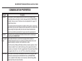
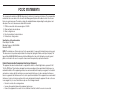
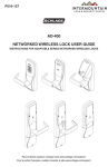
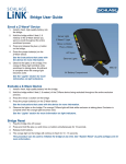
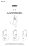
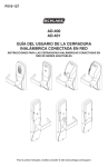
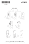
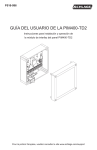
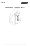
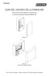
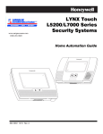
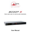
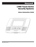
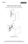
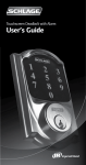
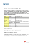
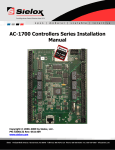
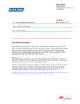
P516-127 AD-400 AD-401 NETWORKED WIRELESS LOCK USER GUIDE INSTRUCTIONS FOR ADAPTABLE SERIES NETWORKED WIRELESS LOCKS Para el idioma español, navegue hacia www.schlage.com/support. Pour la portion française, veuillez consulter le site www.schlage.com/support. AD-400 /AD-401 Networked Wireless Lock User Guide CONTENTS Overview........................................................................................................................................ 3 Getting Started .............................................................................................................................. 4 Handheld Device (HHD) ................................................................................................................ 4 Optional Inside Push Button (IPB) ................................................................................................. 4 User Management ......................................................................................................................... 4 Testing ........................................................................................................................................... 5 Mechanical Testing .................................................................................................................... 5 Electronic Testing ...................................................................................................................... 5 Construction Access Mode ............................................................................................................ 6 Create the Master Construction Credential - Locks with Card Readers .................................... 6 Add User Credentials - Locks with Card Readers ..................................................................... 6 Cancel Construction Access Mode ........................................................................................... 6 Linking to a PIM400 or PIM401 ..................................................................................................... 7 Linking LED and Beep Reference ............................................................................................. 7 Resetting to Factory Default Settings ............................................................................................ 8 Communication Properties ............................................................................................................ 9 Communication Failure .................................................................................................................. 9 Batteries ...................................................................................................................................... 10 Installing or Replacing Batteries .............................................................................................. 10 Low Battery Indications ........................................................................................................... 10 Battery Failure Modes ............................................................................................................. 10 External Power Supply ................................................................................................................ 11 LED and Beep Reference............................................................................................................ 11 Schlage Button ........................................................................................................................ 11 Troubleshooting ........................................................................................................................... 11 FCC/IC Statements ..................................................................................................................... 12 To comply with FCC and Industry Canada RF radiation exposure limits for general population, the antenna(s) used for this transmitter must be installed such that a minimum separation distance of 20cm is maintained between the radiator (antenna) and all persons at all times and must not be co-located or operating in conjunction with any other antenna or transmitter. www.schlage.com/support 877.671.7011 2 AD-400 /AD-401 Networked Wireless Lock User Guide OVERVIEW The Schlage AD-400 is an open architecture Wireless Access Point Module (WAPM) designed to interface with third-party panels through a PIM400. The Schlage AD-401 is FIPS-201 certified Wireless Access Point Module (WAPM) designed to interface with third-party panels through a PIM401-TD2. • The AD-400/AD-401 communicates with the PIM400/PIM401 via RF (radio frequency). • AD-400 communicates with the PIM400 via RF (radio frequency) and may be linked only to a PIM400. • AD-401 communicates with the PIM401 via RF and may be linked only to a PIM401. • May be battery powered or connected to external power using a UL294 Listed Power Supply. See Batteries on page 10 and External Power Supply on page 11 for more information. • The outside lever is normally locked. • The inside lever always allows egress. • The AD-400/AD-401 normally operates in on-line mode. Information contained in the user credential is passed to an access control panel (ACP), which controls lock functions. ACP maintains the audit trail. Outside Schlage Button Outside Lever Keyway Keypad Prox/Smart/Multi-Tech Reader Mag Card (Insert) Reader Mag Card (Swipe) Reader Inside Inside Push Button (IPB) (Optional) Thumbturn Inside Lever Battery Compartment AD-400/AD-401-CY AD-400/AD-401-MS AD-400/AD-401-MD AD-400/AD-401-993 Additional AD-400 Reader options: Mag + Keypad, Prox + Keypad, Smart + Keypad, Multi-Tech + Keypad. The AD-401 reader is a FIPS-201 certified Multi-Tech + Keypad reader. 3 AD-400 /AD-401 Networked Wireless Lock User Guide GETTING STARTED Follow these steps when setting up a new lock. 1. Install the lock. See the installation guide that came with the lock, or visit www.schlage.com/support, for more information. 2. Make sure the batteries are installed properly. See Batteries on page 10 for more information. 3. Configure the Master Construction Credential (where applicable). See Construction Access Mode on page 6 for more information. The lock should remain in Construction Access Mode until you are ready to set up the rest of the wireless access system. 4. Test the lock for proper mechanical and electronic operation. See Testing on page 5 for more information. 5. Link the lock to the PIM400/PIM401. See Linking to a PIM400 or PIM401 on page 7 for more information. 6. Consult the Schlage Utility Software User Guide for information about configuring the lock and PIM400/PIM401. 7. Familiarize yourself with the information contained in this user guide. ! Save this user guide for future reference. HANDHELD DEVICE (HHD) ! The Handheld Device is used for programming and setup only. The Handheld Device (HHD) is used to configure locks. This includes transferring data files between the access control software and locks. For information about the HHD, see the Schlage Utility Software User Guide. OPTIONAL INSIDE PUSH BUTTON (IPB) • The IPB state is communicated to the control panel by the PIM400-485. The manner in which the network access control software utilizes this communication is configured at the host. The IPB may be used to communicate a lock/unlock request or be completely ignored by the network software. • The AD-400 inside push button activity will only be reported to control systems connected to a PIM400-485 with a RS-485 connection. • The IPB may be configured by the ACP or HHD to take direct action on the lock state in case communications from the control system to the AD-400 fail and the lock remains powered. USER MANAGEMENT User management is controlled by the access control system. If the access control panel has not yet been connected, use construction mode to add and delete users. See Construction Access Mode on page 6 for more information. 4 AD-400 /AD-401 Networked Wireless Lock User Guide TESTING If you encounter problems while performing any of the following tests, review the installation guide and correct any problems. Mechanical Testing 1. Rotate the inside lever. Operation should be smooth, and the latch should retract. 2. Insert the key into the keyway and rotate the key or the key and lever to open the door. Operation should be smooth, and the latch should retract. Electronic Testing 1. For locks with a keypad, press any number key. The lock should beep. Press the Schlage button. The keypad should light blue. 2. For locks with a card reader, present a credential to the reader. When the lock is in Construction Access Mode (see Construction Access Mode on page 6) and not connected to an access control panel, the lock should beep and the Schlage light should blink red four (4) times. The first credential presented to a new while holding the Schlage button lock becomes the Master Construction Credential. In normal operating mode and when connected to an access control panel, the lock should beep and the Schlage light should light green. The Schlage light should light red when the credential is not a valid credential for the lock. 5 AD-400 /AD-401 Networked Wireless Lock User Guide CONSTRUCTION ACCESS MODE Construction Access Mode is used to allow access before the lock has been programmed, and for testing purposes. • Enabled by default. • The lock will remain in Construction Access Mode until the mode is cancelled as described below. • No audits are captured while the lock is in Construction Access Mode. Create the Master Construction Credential - Locks with Card Readers ! The first card presented to a new lock automatically becomes the Master Construction Credential! 1. Press and hold the Schlage button while presenting a credential. 2. This credential becomes the Master Construction credential. After you have created the Master Construction Credential, you can then use that card to add construction access mode user credentials. The Master Construction Credential will not grant access. It is used only to add additional credentials. Add User Credentials - Locks with Card Readers TIPS Use the same Master Construction Credential for all the locks in the facility. If you present the first card to a new lock to create the Master Construction Credential and the card is not accepted, the lock has either been programmed or already has a Master Construction Credential. If the Master Construction Credential cannot be located, or to put the lock back into construction access mode, reset the lock to factory settings. See Resetting to Factory Default Settings on page 8 for more information. 1. Present the Master Construction Credential to the lock. The Schlage button will light green. 2. Present the user credential to be added within twenty (20) seconds. The user credential will be added to the lock database. Credentials added using the Master Construction Credential will have normal 24/7 access. Cancel Construction Access Mode Do one of the following: • Authenticate or program the lock with the Handheld Device. See the Schlage Utility Software User Guide for more information. • Reset the lock to factory settings. See Resetting to Factory Default Settings on page 8 for more information. • Link the lock with a PIM400/PIM401. See Linking to a PIM400 or PIM401 on page 7 for more information. ! When construction access mode is cancelled, the Master Construction Credential and all other credentials added using the Master Construction Credential will no longer function. 6 AD-400 /AD-401 Networked Wireless Lock User Guide LINKING TO A PIM400 OR PIM401 Only one AD-400/AD-401 can be linked at a time. Ensure that no other PIM400/PIM401 units are in link mode during this process. 1. Make sure the batteries are installed in the AD-400/AD-401. See Batteries on page 10 for more information. 2. Make sure that the PIM400/PIM401 is in link mode. See the Schlage Utility Software User Guide for more information. 3. Open the door. 4. Create a request-to-exit condition by holding down the inside lever or crash bar. If using a crash bar, Request to Exit (RTX) must be installed. If RTX is not installed, temporarily short the RTX input on the lock main PCB during this procedure. TIP During linking, the Schlage button will blink red and green. Green blinks indicate successful packets and red blinks indicate unsuccessful packets. If you get several red blinks, the lock and PIM may still link, but you may experience intermittent communication in the future. You should move the PIM closer to the lock, select another RF channel or add another PIM. 5. While holding down the lever or crash bar, present a card to the prox or mag card reader. For a keypad reader, press the “#” key. 6. Continue to hold down the lever or crash bar until the Schlage button starts to blink green, indicating that the link process has begun (approximately 8 seconds). 7. Release the lever or crash bar. 8. The Schlage button will blink green, and the beeper will beep. The number of green blinks/beeps indicates the RF channel number. 9. If the link fails, the Schlage button will blink red three (3) times and five (5) short beeps will sound. The PIM400/PIM401 will remain in link mode. Move the PIM400/PIM401 and/or change the RF channels and repeat steps 3 - 7. 10. Test the lock for normal operation. See Testing on page 5 for more information. Re-linking is required anytime the AD-400/AD-401 or PIM400/PIM401 is moved or replaced, Dynamic Channel Switching is activated or the RF channel is manually changed. To re-link, repeat the procedure above. Linking LED and Beep Reference Lights 1 Red, 1 Green Beeps 0 1 Green 1 Red Z Green 1 3 Red 0 0 Z1 5 Action One link request was sent to find a PIM400/PIM401 in link mode. This will repeat once and then the lock will stop trying to find a PIM400/PIM401. Successful RF packet transmission Unsuccessful RF packet transmission Linking was successful1 Linking was unsuccessful 1 Z = RF channel number on which the AD is linked (1-10). The RF channel of each PIM400/PIM401 in the area should be known and recorded. Use this information to make sure the AD-400/AD-401 linked to the intended PIM400/PIM401. 7 AD-400 /AD-401 Networked Wireless Lock User Guide RESETTING TO FACTORY DEFAULT SETTINGS ! All information in the lock will be deleted and reset to factory defaults! 1. Remove the top inside cover. 2. Press and hold Schlage button until two (2) beeps sound (10 seconds). 3. Release the Schlage button. 4. Press and release the inside push button (IPB) three (3) times within 10 seconds. One beep will sound and one red blink will occur with each press. 5. The Schlage button and IPB will both light green for one second and a one-second beep will be heard. This indicates that the lock has been reset. If IPB is not pressed 3 times within 10 seconds, two beeps with two red blinks indicate timeout 6. Replace the top inside cover. 8 AD-400 /AD-401 Networked Wireless Lock User Guide COMMUNICATION PROPERTIES Property Heartbeat Description The heartbeat is a brief communication from the lock to the PIM400/PIM401. The heartbeat allows an idle lock to check for messages from the PIM400/PIM401. By default, this occurs every 10 minutes, but can be adjusted in the range of 15 seconds to many hours. The value indicates the time between the heartbeats. Set the value to a shorter time (lower number) to achieve more frequent communication while the lock is idle. Set the value to a longer time (higher number) to achieve less frequent communication. Immediate Wake-Up On Radio A smaller value will decrease battery life. A larger value will increase battery life. Whenever the lock is used, there is immediate communication to and messages received from the PIM400/PIM401. When enabled, this feature causes the lock to respond within seconds to a centralized command from the access control panel. When disabled, the lock will respond only during its heartbeat, which could result in a delay. Test the function of Wake-Up On Radio, both lock and unlock operations, after all locks are installed. To test, verify that all locks go to the requested state with no assistance or intervention. If test fails, toggle Dynamic Channel Switching (DCS) to its opposite state (off to on, or on to off). Then, re-link all locks and test again. Cache Mode When enabled, the lock keeps a local database of successful access grants. Upon communication failure between the AD-400/AD-401 lock and PIM400/PIM401, access is enabled for Facility Codes or recent valid users. See the Schlage Utility Software User Manual for more information. COMMUNICATION FAILURE When communication fails between the AD-400/AD-401 and the PIM400/PIM401, the lock will go into Communication Failure Mode. This mode can be configured using the HHD. See the Schlage Utility Software User Guide for more information. Mode Fail unlocked Fail locked Fail as-is Description Lock unlocks and remains unlocked until communication is restored. Lock locks and remains locked until communication is restored. Lock remains in current state until communication is restored. In addition, the lock has an internal cache, that can be enabled using the HHD, to allow limited access while lock is offline. See the Schlage Utility Software User Guide for more information. 9 AD-400 /AD-401 Networked Wireless Lock User Guide BATTERIES Installing or Replacing Batteries Approximately one month prior to the end of the battery life, a Low Battery Trouble signal is indicated at the PIM400/PIM401 and a Trouble signal will be sent to the access control panel. 1. Remove the battery cover. 2. Remove the Battery Bracket. 3. Install the new batteries (Install only new AA Alkaline batteries). 4. Install the Battery Bracket. 5. Connect the batteries. 6. Reinstall the battery cover. Depending on how long the battery pack was disconnected, the AD-400/AD-401 may or may not go through its power-up sequence. In either case, there is no need to re-link. ! CAUTION! Danger of explosion if battery is incorrectly replaced! Replace only with the same or equivalent type. Dispose of used batteries according to the manufacturer’s instructions. Four Battery Configuration Eight-Battery Configuration Low Battery Indications Changing batteries does not affect any programmed data. Battery voltage can be checked with the handheld device. Condition Batteries Low Indicator After credential is presented, normal indicator. Battery Failure No LED or beeps (configured Valid credentials do not grant access by HHD) Solution Replace batteries immediately to avoid battery failure. Lock is intended to operate for 500 cycles in low battery condition. Replace batteries immediately. Mechanical override key must be used to unlock lock Battery Failure Modes The battery failure mode is set using the Handheld Device. See the Schlage Utility Software User Guide for more information. Mode Fail As-Is (default) Fail Unlocked 1 Fail Locked 1 Description Lock remains in current state until batteries are replaced. Lock unlocks and remains unlocked until batteries are replaced. Lock locks and remains locked until batteries are replaced. 1 Fail Unlocked and Fail Locked modes are not available if lock is externally powered. 10 AD-400 /AD-401 Networked Wireless Lock User Guide EXTERNAL POWER SUPPLY The AD-400/AD-401 may be connected to external power using a UL 294 Listed power supply capable of sourcing at least 250 mA @ 12 or 24 VDC. + – ide Ins ! Polarity Required If powered with external power supply instead of batteries, lock will always fail as-is if power is lost. LED AND BEEP REFERENCE Beep indicator may be enabled or disabled using the HHD. See the Schlage Utility Software User Guide for more information. Schlage Button Action Extended (Toggle) unlock Card presented and not read Card presented and read No RF communications when card presented Access denied Access granted, momentary unlock (motor runs) Relock (motor runs) Lights Beeps 2 Green 0 None 0 None 1 1 Red 0 Controlled by ACP via PIM400/PIM401 1 Green 0 1 Red 1 TROUBLESHOOTING For troubleshooting, browse to www.schlage.com/support. 11 FCC/IC STATEMENTS The communication module is a 900 MHz transceiver for electronic locks and non-lock devices. The communication module links the access device to the Access Control Management System, with feedback control to the Access Device via a wireless means. The module contains the embedded firmware implementing the radio physical and data layers. There are 5 antennas associated with this module: 1. PCB trace inverted-L with a measured gain of 5.7 dBi. 2. Omni, wall/post, indoors/outdoors. 3. Omni, ceiling, indoors. 4. Directional, wall/post, indoors/outdoors. 5. Bi-directional, ceiling, indoors. Specifications of the radio module: Power Output: 19.6 dBm Operating Frequency: 906 -924 MHz Modulation: BPSK NOTE: The intended use of this module is not for the general public. It is generally for industry/commercial use only. This transceiver is to be professionally installed in the end product by Ingersoll Rand, and not by a third party. The Ingersoll Rand AD400 900 MHz Communication Board Module will not be sold to third parties via retail, general public or mail order. In the case of a repair, the transceiver will be replaced by a professional Installer. Federal Communication Commission Interference Statement This equipment has been tested and found to comply with the limits for a Class B digital device, pursuant to Part 15 of the FCC Rules. These limits are designed to provide reasonable protection against harmful interference in a residential installation. This equipment generates, uses and can radiate radio frequency energy and, if not installed and used in accordance with the instructions, may cause harmful interference to radio communication. However, there is no guarantee that interference will not occur in a particular installation. If this equipment does cause harmful interference to radio or television reception, which can be determined by turning the equipment off and on, the user is encouraged to try to correct the interference by one of the following measures: • Reorient or relocate the receiving antenna. • Increase the separation between the equipment and receiver. • Connect the equipment into an outlet on a circuit different from that to which the receiver is connected. • Consult the dealer or an experienced radio/TV technician for help. This device complies with Part 15 of the FCC Rules. Operation is subject to the following two conditions: (1) This device may not cause harmful interference, and (2) this device must accept any interference received, including interference that may cause undesired operation. FCC/IC Caution Any changes or modifications not expressly approved by the party responsible for compliance could void the user’s authority to operate this equipment. To comply with FCC/IC RF exposure limits for general population/uncontrolled exposure, the antenna(s) used for this transmitter must be installed to provide a separation distance of at least 20 cm from all persons and must not be co-located or operating in conjunction with any other antenna or transmitter. INDUSTRY CANADA STATEMENTS Operation is subject to the following two conditions: (1) this device may not cause interference, and (2) this device must accept any interference, including interference that may cause undesired operation of the device. To reduce potential radio interference to other users, the antenna type and its gain should be so chosen that the equivalent isotropically radiated power (e.i.r.p.) is not more than that permitted for successful communication. This device has been designed to operate with the antennas listed below, and having a maximum gain of 9.3 dBi. Antennas not included in this list or having a gain greater than 9.3 dBi are strictly prohibited for use with this device. The required antenna impedance is 50 ohms. Approved antenna list Model Number 23530553 1 Remote antenna, Omni, wall/post, indoors/outdoors 23530561 1 Remote antenna, Omni, ceiling, indoors 23530579 1 Remote antenna, Directional, wall/post, indoors/outdoors 23530587 1 Remote antenna, Bi-directional, ceiling, indoors To comply with IC RF exposure limits for general population/uncontrolled exposure, the antenna(s) used for this transmitter must be installed to provide a separation distance of at least 20 cm from all persons and must not be collocated or operating in conjunction with any other antenna or transmitter. These units were tested by UL with the Schlage SMS (model #SRCNX) and Bright Blue (model #SBB) Access Control Panels. ©2010 Ingersoll-Rand Company P516-127 ENG online Rev. 08/10-c