1
Version 2.2
1
2
COLORSPOT 250 AT
Table of contents
1. Safety instructions ......................................................................................................... 4
2.Operating determinations .............................................................................................. 5
3. Description of the device .............................................................................................. 6
4. Installation ...................................................................................................................... 7
4.1Fitting the lamp ........................................................................................................... 7
4.2 Lamp adjustment ....................................................................................................... 8
4.3 Inserting/Exchanging gobos and colours .................................................................. 8
4.4 Replacing the 3-facet prism ....................................................................................... 9
4.5 Installation of an optional lens ................................................................................. 10
4.6 Rigging the fixture ................................................................................................... 11
4.7 Connection to the mains .......................................................................................... 12
4.8 Changing the power supply settings-magnetic ballast ............................................ 12
4.9 DMX-512 connection/connection between fixtures ................................................. 13
5. Colorspot 250 AT-DMX Protocol-version 2.1 ............................................................. 15
6. Controller mode ........................................................................................................... 19
6.1 DMX addressing ..................................................................................................... 19
6.2 Remotely controllable functions .............................................................................. 19
7. Stand - alone mode ...................................................................................................... 20
8. Functions of the control panel .................................................................................... 21
8.1 Addressing .............................................................................................................. 21
8.2 Slave control ........................................................................................................... 22
8.3 Fixture informations ................................................................................................. 22
8.4 Personality options .................................................................................................. 24
8.5 Switching On/Off the lamp ....................................................................................... 30
8.6 Manual mode .......................................................................................................... 30
8.7 Test sequences........................................................................................................ 31
8.8 Stand-alone setting ................................................................................................. 31
8.9 Reset function ......................................................................................................... 33
8.10 Special functions ................................................................................................... 33
9. Power down mode ....................................................................................................... 34
10. Error and information messages .............................................................................. 35
11. Technical specifications ............................................................................................ 37
12. Maintenance and cleaning ........................................................................................ 40
3
CAUTION!
Keep this device away from rain and moisture!
Unplug mains lead before opening the housing!
FOR YOUR OWN SAFETY, PLEASE READ THIS USER MANUAL CAREFULLY
BEFORE YOU INITIAL START - UP!
1. Safety instructions
Every person involved with installation and maintenance of this device have to:
- be qualilfied
- follow the instructions of this manual
CAUTION!
Be careful with your operations.
With a high voltage you can suffer
a dangerous electric shock when touching the wires!
This device has left our premises in absolutely perfect condition. In order to maintain this condition and to ensure
a safe operation, it is absolutely necessary for the user to follow the safety instructions and warning notes written
in this manual.
Important:
The manufacturer will not accept liability for any resulting damages caused by the non-observance of this manual
or any unauthorized modification to the device.
Please consider that damages caused by manual modifications to the device are not subject to warranty.
Never let the power-cord come into contact with other cables! Handle the power-cord and all connections with the
mains with particular caution!
Make sure that the available voltage is not higher than stated on the rear panel.
Always plug in the power plug least. Make sure that the power-switch is set to off -position before you connect the
device to the mains. The power-plug has to be accessable after installing the device.
Make sure that the power-cord is never crimped or damaged by sharp edges. Check the device and the powercord from time to time.
Always disconnect from the mains, when the device is not in use or before cleaning it. Only handle the power-cord
by the plug. Never pull out the plug by tugging the power-cord.
This device falls under protection class I. Therefore it is essential to connect the yellow/green conductor to earth.
The electric connection, repairs and servicing must be carried out by a qualified employee.
Do not connect this device to a dimmer pack.
Do not switch the fixture on and off in short intervals as this would reduce the lamp’s life.
During the initial start-up some smoke or smell may arise. This is a normal process and does not necessarily
mean that the device is defective.
Do not touch the device’s housing bare hands during its operation (housing becomes hot)!
For replacement use lamps and fuses of same type and rating only.
CAUTION ! EYEDAMAGES !
Avoid looking directly into the light source
(meant especially for epileptics) !
4
2.Operating determinations
This device is a moving-head spot for creating decorative effects and was designed for indoor use only.
If the device has been exposed to drastic temperature fluctuation (e.g. after transportation), do not switch it on
immediately. The arising condensation water might damage your device. Leave the device switched off until it has
reached room temperature.
Never run the device without lamp!
Do not shake the device. Avoid brute force when installing or operating the device.
Never lift the fixture by holding it at the projector-head, as the mechanics may be damaged. Always hold the
fixture at the transport handles.
When choosing the installation-spot, please make sure that the device is not exposed to extreme heat, moisture
or dust. There should not be any cables lying around. You endanger your own and the safety of others!
The minimum distance between light-output and the illuminated surface must be more than 1,3 meter.
Make sure that the area below the installation place is blocked when rigging, derigging or servicing the fixture.
Always fix the fixture with an appropriate safety-rope. Fix the safety-rope at the correct holes only.
Only operate the fixture after having checked that the housing is firmly closed and all screws are tightly fastened.
The lamp must never be ignited if the objective-lens or any housing-cover is open, as discharge lamps may
explose and emit a high ultraviolet radiation, which may cause burns.
The maximum ambient temperature 45° C must never be exceeded. Otherwise, the lamp is switched off and the
fixture is out of operation for 5 minutes.
CAUTION!
The lens has to be replaced when it is obviously damaged,
so that its function is impaired, e. g. due to cracks or deep scratches!
Operate the device only after having familiarized with its functions. Do not permit operation by persons not
qualified for operating the device. Most damages are the result of unprofessional operation!
CAUTION!
The lamp has to be replaced when it is damaged
or deformed due to the heat!
Please use the original packaging if the device is to be transported.
Please consider that unauthorized modifications on the device are forbidden due to safety reasons!
If this device will be operated in any way different to the one described in this manual, the product may suffer
damages and the guarantee becomes void. Furthermore, any other operation may lead to dangers like shortcircuit, burns, electric shock, burns due to ultraviolet radiation, lamp explosion, crash etc.
5
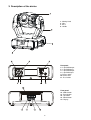
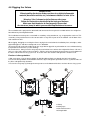
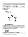
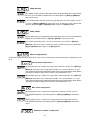
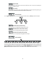
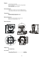
3. Description of the device
1 - Moving Head
2 - Yoke
3 - Base
4 - Handle
Rear panel:
5 - 5-pin DMX output
6 - 5-pin DMX input
7 - 3-pin DMX output
8 - 3-pin DMX input
9 - Power switch
10 - Power cord
11 - Fuse holder
Front panel:
12 - Mode-button
13 - Enter-button
14 - Up-button
15 - Down-button
16 - Display
6
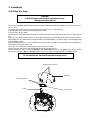
4. Installation
4.1Fitting the lamp
DANGER !
Install the lamps with the device switched off only.
Unplug from mains before !
To insert the lamp MSD 250W/2 open the top cover of the projector-head by loosening the 3 quarter-turn fasteners
on the cover.
Then open the small lamp cover by loosening 2 fastening screws (see the drawing).
If changing the lamp, remove the old lamp from the socket.
Insert the lamp to the socket.
Do not install a lamp with a higher wattage! A lamp like this generates temperatures the device is not designed
for.
Damages caused by non-observance are not subject to warranty. Please follow the lamp manufacturer‘s notes!
Do not touch the glass bulb with bare hands during the installation! Make sure that the lamp is installed tightly into
the lampholder system.
Adjust the optimal distance 1-1.5 mm from the lens by turning the screw "A" (see the drawings "Lamp adjustment"
below) on the rear panel of the head.
Then close the small lamp cover by tighten 2 fastening screws again.
Reclose the top cover of the head and tighten the 3 quarter-turn fasteners.
Before striking the lamp, reset the "LAti/rSEt" and "LASt/rSEt"counters in the "InFO" menu on the control
panel, by pressing the "Up" and "Down" buttons in one time and then confirming with the "Enter"-button.
Do not operate this fixture with opened housing-cover!
quarter-turn fasteners
Top cover
Fastening screws
Lamp
Lamp cover
7
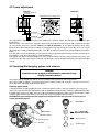
4.2 Lamp adjustment
Correct
optimum distance
1-1,5 mm
Incorrect
rear panel of the moving head
Screw"B"
Screw"A"
The lampholder is aligned at the factory. Due to differences between lamps, fine adjustment may improve light
performance.
Strike the lamp, cancel all effects, open the shutter and set the dimmer intensity onto 100 % and focus the light
on a flat surface (wall) or use function "LAAd" in the Special functions . As the optimum distance of the lamp
from lens was adjusted during the installing or changing the lamp (by turning the screw "A"), it is necessary to
adjust only the second position by turning the screw "B", in order to center the hot-spot (the brightest part of the
beam).
If the hot spot seems to be too bright, you can lower its intensity by moving the lamp closer to the reflector. Do so
by turning the srew "A" until the light is evenly distributed.
If the light on the edge seems to be brighter as in the center, the lamp is too close at the reflector. In this case, you
need to move the lamp away from the reflector until the light is evenly distributed and the beam appears bright
enough.
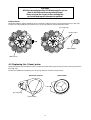
4.3 Inserting/Exchanging gobos and colours
DANGER!
Install the colours and gobos with the device switched off only.
Unplug from mains before!
Turn off the lamp and allow it to cool for at least 10 minutes.Disconnect the fixture from power.
To insert the gobos or colours, open the top cover of the moving-head by loosening the 3 quarter-turn fasteners
on the top cover and follow the instructions below:
Rotating gobo-wheel:
1.Gently bend out the gobo module to release it from the distance holes and eject it from the pressing snap.
2.Press the ends of the fixation ring together with an appropriate tool and remove it from the gobo holder.Remove
the gobo and insert the new gobo . Press the ends of the fixation ring together and insert it in the front of the gobo.
3.Put the gobo module back under the pressing snap and push it to the 2 distance holes.
CAUTION!The gobo module with the magnet must be placed in the same position as it was placed
before gobo replacement!
.
gobo holder
gobo module
distance holes
gobo - glazy side
towards the lamp!
distance ring
pressing snap
magnet
fixation ring
8
CAUTION!
All Gobos were designed for 250 W lamp only.Do not use
them in the fixture with more powerful lamp!
Never unscrew the screws of the rotating gobo
as the ball bearing will otherwise be opened!
Colour-wheel:
Gently bend out the colour-module to release it from the 2 distance holes and eject it from the pressing snap.
Put the new colour-module back under the pressing snap and push it to the 2 distance holes.
pressing snap
fixative holes
colour-module
colour-wheel
4.4 Replacing the 3-facet prism
Gently bend out the prism holder to release it from the fixative holes of prism/frost fastener and eject it from the
pressing snap.
Put the frost holder back under the pressing snap and push it to the 3 fixative holes.
prism holder
prism/frost fastener
pressing snap
fixative holes
9
4.5 Installation of an optional lens
The device is delivered with a 15°-standard lens. If you wish to insert an optional 12° or 18°-lens (it is not the
standard part of delivery), please follow the instructions below:
Optional 12°-lens:
Remove the fixation-ring of the 15°-lens with an appropriate tool. Remove the lens. Install the optional 12°-lens
and fix it with the fixation-ring.
standard 15°lens
12°lens
Optional 18°-lens:
Unscrew the knurled-head screw on the plate of the light-output. Install the optional 18°-lens and fix it with the
knurled-head screw.
18°lens
knurled-head screw
knurled-head screw
standard 15° lens
10
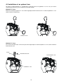
4.6 Rigging the fixture
Danger of fire !
When installing the device, make sure there is no highly inflammable
material (decoration articles, etc.) in between a distance of min. 0,5 m.
Warning ! Use 2 clamps to rig the fixture on the truss.
Follow the instructions mentioned at the bottom of the base.
Make sure that the device is fixed properly! Ensure that
the structure (truss) to which you are attaching the fixtures is secure.
The installation of the projector has to be built and constructed in a way that it can hold 10 times the weight for 1
hour without any harming deformation.
The installation must always be secured with a secondary safety attachment, e.g. an appropriate catch net. This
secondary safety attachment must be constructed in a way that no part of the installation can fall down if the
main attachment fails.
When rigging, derigging or servicing the fixture staying in the area below the installation place, on bridges, under
high working places and other endangered areas is forbidden.
The moving-head can be placed directly on the stage floor or rigged in any orientation on a truss without altering
its operation characteristics (see the drawing).
For overhead use, always install a safety-rope that can hold at least 10 times the weight of the fixture. You must
only use safety-ropes with screw-on carabines. Pull the safety-rope through the two apertures on the bottom of
the base and over the trussing system etc. Insert the end in the carabine and tighten the fixation screw.
Fixation via Omega holders
1.Bolt each clamp (1) to the omega holder (4) with M12 bolt and lock nut through the hole in the holder.
2.Fasten the omega holders on the bottom of the base by inserting both quick-lock fasteners (3) into the holes of
the base and tighten fully clockwise.
3.Fasten the safety-rope (2) through the two apertures on the bottom of the base and over the trussing system.
1-Clamp
2-Safety-rope
3-Quick-lock fastener
4-Omega holder
11
4.7 Connection to the mains
Verify the power supply settings before applying power!
If you wish to change the power supply settings,see the chapter below.
Connect the fixture to the mains with the enclosed power cord and plug.
The earth has to be connected!
The occupation of the connection-cables is as follows:
Cable (EU)
Cable (US)
Pin
International
Brown
Black
Live
L
Light blue
White
Neutral
N
Yellow/Green
Green
Earth
4.8 Changing the power supply settings-magnetic ballast
Both the transformer and the ballast must be connected correctly for the local AC voltage and frequency.
The wrong settings can cause poor performance or demage of the moving head.The factory settings are printed
next to the power switch.
If you want to change the power supply settings,follow the instructions:
1.Disconnect the fixture from AC power.
2.Remove the 2 top base covers by loosening 10 screws.
3.Move the wire 1 on the transformer connection block to the position according to the desired voltage.
4.Move the wires 2 and 3 on the ballast connection block to the position according to the desired frequency
(voltage).
5.Close the base before applying AC power.
Examples:
EU-version
power supply settings: 230V/50Hz
12
US-version
power supply settings: 120V/60Hz
4.9 DMX-512 connection/connection between fixtures
he fixture is equipped with both 3-pin and 5-pin XLR sockets for DMX input and output.The sockets are wired in
parallel.
Only use a shielded twisted-pair cable designed for RS-485 and 3-pin or 5-pin XLR-plugs and connectors in order
to connect the controller with the fixture or one fixture with another.
Occupation of the XLR-connection:
DMX - output
DMX-input
XLR mounting-sockets (rear view):
XLR mounting-plugs (rear view):
1 - Shield
2 - Signal (-)
3 - Signal (+)
4 - Not connected
5 - Not connected
1 - Shield
2 - Signal (-)
3 - Signal (+)
4 - Not connected
5 - Not connected
Controller operation
Master/slave operation
13
Building a serial DMX-chain:
If you are using the standard DMX-controllers, you can connect the DMX-output of the controller directly with the
DMX-input of the first fixture in the DMX-chain. If you wish to connect DMX-controllers with other XLR-outputs,
you need to use adapter-cables.
Connect the DMX-output of the first fixture in the DMX-chain with the DMX-input of the next fixture. Always
connect output with the input of the next fixture until all fixtures are connected.
Caution: At the last fixture, the DMX-cable has to be terminated with a terminator. Solder a 120 Ohm resistor
between Signal (–) and Signal (+) into a 3-pin XLR-plug and plug it in the DMX-output of the last fixture.
Building a master/slave-chain:
Connect the DMX-output of the master fixture in the data-chain with the DMX-input of the first slave. Always
connect output with the input of the next slave until all slaves are connected (up to 9 fixtures).
Caution:It’s necessary to insert the XLR termination plug (with 120 Ohm) into the input of the master fixture and
into the output of the last slave fixture in the link in order to ensure proper transmission on the data link.
14
5. Colorspot 250 AT-DMX Protocol-version 2.1
Mode/Channel
1
2
3
4
1
1
1
2
2
2
3
3
3
3
4
4
4
4
5
5
2
5
1
5
Value
Pan
Pan movement by 530°
proportional
0-255
Pan fine
Fine control of pan movement
proportional
0-255
Tilt
Tilt movement by 280°
proportional
0-255
Tilt fine
Fine control of tilt movement
proportional
Pan/Tilt speed , Pan/Tilt time
Max.speed (tracking mode)
step
0
1-255
6
6
6
7
P./T. speed- set Speed Mode in menu: P.t.Mo.
Speed from max. to min. (vector mode)
P./T. time - set Time Mode in menu: P.t.Mo.
Time from 0.1s to 25.5s. *
130-139
140-149
150-159
160-169
170-179
180-189
190-199
200-209
210-229
230-239
240-255
Power/Special functions
Reserved
To activate following functions, stop in DMX value
for at least 3 s and shutter must be closed at least
3 s.("Shutter,Strobe" channel 16(13,18,15) must be
at range:0-31 DMX).**
Pan/Tilt speed mode
Pan/Tilt time mode
Blackout while pan/tilt moving
Disabled blackout while pan/tilt moving
Blackout while colour wheel moving
Disabled blackout while colour wheel moving
Blackout while gobo wheel moving
Disabled blackout while gobo wheel moving
To activate following functions, stop in DMX value
for at least 3 s.
Lamp On,reset(total reset except pan/tilt reset)
Pan/Tilt reset
Colour wheel reset
Gobo wheel reset
Dimmer/Strobe reset
Focus reset
Prism reset
Total reset
Reserved
Lamp Off
Reserved
0-9
10-31
32-63
64-95
96-127
128-159
160-191
192-223
224-255
Pan/Tilt macro selection
Disabled pan/tilt macro
Reserved
Figure of circle (from small to large)
Figure of horizontal eight (from small to large)
Figure of vertical eight (from small to large)
Figure of rectangle (from small to large)
Figure of triangle (from small to large)
Figure of five-pointed star (from small to large)
Figure of cross (from small to large)
0-49
50-59
60-69
70-79
80-89
90-99
100-109
110-119
120-129
7
Type of control
0-255
1-255
6
Function
15
proportional
proportional
step
step
step
step
step
step
step
step
step
step
step
step
step
step
step
step
step
step
step
step
step
step
proportional
proportional
proportional
proportional
proportional
proportional
proportional
Mode/Channel
1
2
3
4
8
Value
8
0
1-127
128-129
130-255
7
7
9
9
9
10
8
11
Pan/Tilt macro speed
Set pan/tilt speed (channel 5) to 0
No macro generation
Macro generation from fast to slow -forwards
No macro generation
Macro generation from slow to fast- backwards
Type of control
step
proportional
step
proportional
250-255
Colour wheel
In range 0-128 DMX is possible fine colour
positioning- set value on channel 8 (10)
Open/white
Dark green
Red
Light azure
Magenta
UV filter
Yellow
Green
Pink
Blue
Deep red
White
Dark green
Red
Light azure
Magenta
UV filter
Yellow
Green
Pink
Blue
Deep red
Forwards rainbow effect from fast to slow
No rotation
Backwards rainbow effect from slow to fast
Random colour selection by audio control
(Set microphone sensitivity in menu "Personality")
Auto random colour selection from fast to slow
0-255
Colour wheel-fine positioning
Fine positioning
proportional
Rotating gobo wheel
Index - set indexing on channel 10 (9,12,11)
Open/hole
Gobo 1 (15030016)
Gobo 2 (15040011)
Gobo 3 (15020137)
Gobo 4 (15020138)
Gobo 5 (15020139)
Gobo 6 (15020140)
Gobo 7 (15020141)
step
step
step
step
step
step
step
step
0
11
23
34
46
58
70
81
93
105
117
128
130-135
136-141
142-147
148-153
154-159
160-165
166-171
172-177
178-183
184-189
190-215
216-217
218-243
244-249
8
Function
10
0-3
4-7
8-11
12-15
16-19
20-23
24-27
28-31
32-35
36-39
40-43
44-47
48-51
Rotation - set rotation on channel 10 (9,12,11)
Gobo 1
Gobo 2
Gobo 3
Gobo 4
Gobo 5
16
proportional
proportional
proportional
proportional
proportional
proportional
proportional
proportional
proportional
proportional
proportional
proportional
step
step
step
step
step
step
step
step
step
step
proportional
step
proportional
step
proportional
step
step
step
step
step
Mode/Channel
1
2
3
4
Value
52-55
56-59
60-69
70-79
80-89
90-99
100-109
110-119
120-129
130-139
140-149
150-159
160-169
170-179
180-189
190-199
200-201
202-221
222-223
224-243
244-249
250-255
10
9
12
11
0-255
0
1-127
128-129
130-255
11
13
0-255
12
10
14
12
0-19
20-159
160-255
160-167
168-175
176-183
184-191
192-199
200-207
208-215
216-223
224-231
232-239
Function
Type of control
Gobo 6
Gobo 7
step
step
Shaking gobos from slow to fast
Index - set indexing on channel 10 (9,12,11)
Gobo 1
Gobo 2
Gobo 3
Gobo 4
Gobo 5
Gobo 6
Gobo 7
proportional
proportional
proportional
proportional
proportional
proportional
proportional
Shaking gobos from slow to fast
Rotation - set rotation on channel 10 (9,12,11)
Gobo 1
Gobo 2
Gobo 3
Gobo 4
Gobo 5
Gobo 6
Gobo 7
Open/hole
Forwards gobo wheel rotation from fast to slow
No rotation
Backwards gobo wheel rotation from slow to fast
Random gobo selection by audio control
(Set microphone sensitivity in menu "Personality")
Auto random gobo selection from fast to slow
Gobo indexing and rotation
Gobo indexing -set pos. on channel 9 (8,11,10)
Gobo indexing
Gobo rotation -set pos. on channel 9 (8,11,10)
No rotation
Forwards gobo rotation from fast to slow
No rotation
Backwards gobo rotation from slow to fast
proportional
proportional
proportional
proportional
proportional
proportional
proportional
step
proportional
proportional
step
proportional
proportional
step
proportional
step
proportional
Gobo fine indexing
(set position on channel 9 (8,11,10)
Fine indexing
proportional
Prism
Open position (hole)
3-facet rotating prism
Prism/gobo macros
Macro 1
Macro 2
Macro 3
Macro 4
Macro 5
Macro 6
Macro 7
Macro 8
Macro 9
Macro 10
step
step
step
step
step
step
step
step
step
step
step
step
step
17
Mode/Channel
1
2
3
4
Value
240-247
248-255
13
11
14
12
15
16
17
18
*
**
15
16
13
14
17
13
18
15
14
19
16
20
Function
Type of control
Macro 11
Macro 12
step
step
Prism rotation
No rotation
Forwards rotation from fast to slow
No rotation
Backwards rotation from slow to fast
step
proportional
step
proportional
0-255
Focus
Coarse focus
proportional
0-255
Focus fine
Fine focus adjustment
0
1-127
128-129
130-255
0-31
32-63
64-95
96-127
128-143
144-159
160-191
192-223
224-255
0-255
0-255
Shutter,Strobe
Shutter closed
No function (shutter open)
Strobe-effect from slow to fast
No function (shutter open)
Opening pulse in sequences from slow to fast
Closing pulse in sequences from fast to slow
No function (shutter open)
Random strobe-effect from slow to fast
No function (shutter open)
step
step
proportional
step
proportional
proportional
step
proportional
step
Dimmer
Coarse gradual adjustment of the dimmer intensity proportional
from 0 to 100%
Dimmer fine
Dimmer intensity fine
proportional
Short times are not used for long tracks( e.g. 0.5s for track 0-255 DMX).Times are restricted by
mechanical parameters of the fixture.
The switch-functions have priority to the equivalent functions in menu "Personality"but the setting
by DMX is not saved to the memory( after switching the fixture on,the setting from menu "Personality"
is loaded and after that can by changed with DMX value on the channel 6).
DMX protocol
menu "PerS"
50-59 Pan/Tilt speed mode
P.t.Mo.--->SP.Mo.
60-69 Pan/Tilt time mode
P.t.Mo.--->ti.Mo.
70-79 Blackout while pan/tilt moving
A.blc.-->P.t.M.-->On
80-89 Disabled blackout while pan/tilt moving
A.blc.-->P.t.M.-->Off
90-99 Blackout while colour wheel moving
A.blc.-->Col.M.-->On
100-109 Disabled blackout while colour wheel moving A.blc.-->Col.M.-->Off
110-119 Blackout while gobo wheel moving
A.blc.-->Gob.M.-->On
120-129 Disabled blackout while gobo wheel moving A.blc.-->Gob.M.-->Off
18
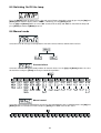
6. Controller mode
The fixtures are individually addressed on a data link and connected to the controller.The fixtures respond to the
DMX signal from the controller.
6.1 DMX addressing
The control panel on the front panel of the fixture allows you to assign the DMX fixture address, which is defined
as the first channel from which the COLORSPOT 250 AT will respond to the controller.
If you set, for example, the address 19, the COLORSPOT 250 AT will use the channel 19 to 36 for control (if Mode
1 is selected).
Please, be sure that you don’t have any overlapping channels in order to control each COLORSPOT 250 AT
correctly and independently from any other fixture on the DMX data link.
If two, three or more COLORSPOT 250 AT are addressed similarly, they will work similarly.
For address setting, please refer to the instructions under "Addressing"(menu "A001").
Controlling:
After having addressed all COLORSPOT 250 AT , you may now start operating these via your lighting controller.
Note:After switching on, the COLORSPOT 250 AT will automatically detect whether DMX 512 data is received or
not.If there is no data received at the DMX-input, the display will start to flash "A001" with actually set address.
This situation can occur if:
- the 3 PIN XLR plug (cable with DMX signal from controller) is not connected with the input of the COLORSPOT
250 AT
- the controller is switched off or defective, the cable or connector is defective or the signal wires are swap in the
input connector.
Note:It’s necessary to insert the XLR termination plug (with 120 Ohm) to the last fixture in the link in order to
ensure proper transmission on the DMX data link.
6.2 Remotely controllable functions
Lamp
The COLORSPOT 250 AT is to be operated with a MSD 250/2 GY-9,5 lamp.
A relay inside of the COLORSPOT 250 AT allows you to switch on and off the lamp via the control panel or via
your DMX-controller without affecting the rest of the lighting.
To switch On/Off the lamp, please refer to "Switching On/Off the lamp " (menu "LAMP").
Note: It is also important to note, that the discharge lamp is cold restrike types, that means, that they have to be
cold before re-striking. For this reason, you have to wait 5 minutes (max. speed of fan must be adjusted) after
having switched Off the lamp before you can switch it back On again. If you try to switch On the lamp within 5
minutes after having switched it Off, the COLORSPOT 250 AT will store this information and automatically ignite
the lamp when the 5 minutes period has expired. The message "HEAt" will appear on the control panel display of
the COLORSPOT 250 AT. If the ignition of the lamp is seven times unsuccessful, on the display will appear
"LA.Er", meaning that the lamp could be damaged or even missed, or there could be a failure on the ignitor or
ballast.
Colour wheel
The COLORSPOT 250 AT features a colour wheel with 11 colour positions - 10 of these with dichroic colors and
the last one open. The wheel can be positioned between two adjacent colors in any position. All colours are easy
replaceable.It is also possible to rotate the color-wheel continuously at different speeds - the so-called "Rainbow
effect“ is created.
Rotating gobo wheel
The rotating gobo-wheel includes 7 gobos rotating in both directions, indexable, rotating gobo wheel cont. rotation
from slow to fast. All gobos are easy replaceable.
3-facet rotating prism / frost filter
3-facet prism (rotating in both directions at different speeds) can be replace by frost filter.
Focus
Motorized focus enables the beam to be focused anywhere on the stage.
19
Dimmer/Shutter/Strobe
Smooth 0 - 100 % dimming is provided by the combined mechanical dimmer/shutter unit. This unit may also be
used for strobe effect (1 - 10 flashes per second)
Fans
The COLORSPOT 250 AT is cooled by 3 axial fans - two in the projector head and one in the base. The speed of
the fans (and of course the noise) can reduced using mode "Auto" if very quiet performance is required.
7. Stand - alone mode
The fixtures on a data link are not connected to the controller but can execute pre-set programs which can be
different for every fixture.To set the program to be played,see the "Stand-alone setting" ( menu "St.AL.").
"Stand-alone operation" can be applied to the single fixture (the fixture may be set to the master /slave mode or
controller mode ) or to multiple fixtures operating synchronously.
Synchronous operation of multiple fixtures requires that they must be connected on a data link and one of them
is set as a master (master mode) and the rest as the slaves (slave mode).The slaves are assigned to SLA1SLA9 and on the certain slave address can be connected only one fixture.To set the fixture as the master or
slave , see the "Addressing" (menu "A001").
If the master fixture runs a reset,switches On/Off the lamp or plays test(program) ,all slaves will execute
these acts too (e.g. if the master fixture has switched the lamp off,no slaves can switch the lamp on)!
You can't play or edit any programs on the slaves by their control panels if the master is switched on and
connected to the master/slave chain.
The master fixture starts simultaneous program start in the other slave fixtures.All fixtures have a definite,
synchronized starting point when playing back their programs.The number of running program is the same in all
slaves and depends on the master's choice (menu "St.AL." ).Every fixture runs its program repeatedly ,starting
the program step No.1 when requested by the master .
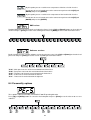
For example:
If the slave fixture has a shorter program length, it will continously repeat its program until the master fixture
finishes its own program and restarts its program running (slave 1- prog.step 3 will not be finished).
If the slave fixture has a longer program length, it will restart at prog. step 1 before it completes all its prog.steps
(slave 2 - prog.step 5 will not be played)- see the picture bellow.
Restart
Starting point
Note:Disconect the fixtures from the DMX controller before master/slave operating ,otherwise data collisions can
occur and the fixtures will not work properly!
It’s necessary to insert the XLR termination plug (with 120 Ohm) into the input of the master fixture and into the
output of the last slave fixture in the data link in order to ensure proper transmission on the data link.
From the master's control panel is possible to control any slave in a master/slave chain.
20
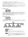
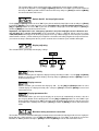
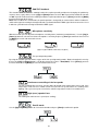
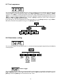
8. Functions of the control panel
The control panel situated on the front side of the base offers several features. You can simply set the DMX
address,master/slave mode, read the number of lamp or unit hours, switch On and Off the lamp, run test, make
a reset and also use many functions for setting and service purposes.
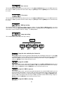
The main menu of the control panel is accessed by pressing the [Mode] button - press this one so many times
until the display shows message "A001" (with actually stored address). Browse through the menu by the pressing
[Up] or [Down] buttons - the display shows step by step these messages:
Press [Enter] if you wish to select one of them. The functions are described in the following sections and the
function hierarchy is shown below.
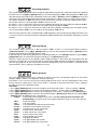
8.1 Addressing
By this menu you can set the DMX address or address the fixture as a master/slave.
DMX addressing
1. Press the [Mode]- button so many times until the display shows message "A001" (with actually stored address).
2. Press [Enter]-button and use the [Up] and [down] buttons to select"dM.Ad."-menu.
3. Press[Enter]-button(the letter "A" flashes) and by [Up] and [down] buttons select required address,press
[Enter]-button to confirm.
4. Select "M.ASL."-menu,press[Enter]-button and use [Up] and [down] buttons to select "d.AbL."(no master or
slave),press [Enter] to confirm.
5. Press the [Mode]- button.Choosen address is shown on the display.
If message "A001" (with actually stored address) flashes-no DMX data received at the DMX-input.
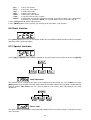
Master/slave adressing
1. Press the [Mode] button so many times until the display shows message "A001"(with actually stored address).
2. Press [Enter]-button and use the [Up] and [down] buttons to select "MA.SL."-menu.
3. Press[Enter]-button(display flashes) and select"MASt"(to set the fixture as the master in a chain of multiple
fixtures) or "SLA.1"-"SLA.9" (to set the fixture to be the slave in a chain of multiple fixtures) and press [Enter]
to confirm. If you want address no master or slave, select "d.AbL.".
21
4. Press the [Mode]- button.Choosen address is shown on the display.
If message "MASt." fast flashes-DMX signal is received at the DMX-input- disconnect DMX controller!
Only one fixture may be the master. Up to the 9 slaves may be connected to the master and on the certain
address can be connected only one slave fixture (SLA1-SLA9).
Note:Disconect the fixtures from the DMX controller before master/slave operating ,otherwise data collisions can
occur and the fixtures will not work properly!
If the fixture is set as the master and DMX signal is connected to its input,the error massage "MAEr" will appear
on its display and the fixture's address will be set to its DMX address.
8.2 Slave control
This function allows you to control the slaves from the master's control panel in a master/slave operation.
Select this function from the main menu and press [Enter]-button.Browse the list of all connected slaves ("SL.C.1"
- "SL.C.9") by pressing [Up] or [Down] button.Select the desired slave and press [Enter]-button.The slave's
control panel is available from the master's control panel.
If no slave is connected to the master,massages "SL.C.1","SL.C.2","SL.C3"..."SL.C.9" still round repeat.
Note:This function is available from the master fixture only.
8.3 Fixture informations
The menu allows you to read an useful information about the fixture as the lamp life,head temperature,software
version, etc.
Press [Up] and [Down] buttons to select the desired option and press [Enter] to see the value or next submenu.
Power On time
-By this option you can read the total number of the operation hours since the
COLORSPOT 250 AT has been fabricated. Press [Enter] or [Mode] to return to the
menu.
- The number of the hours that the COLORSPOT 250 AT has been powered On since
the counter was last reset.Press [Enter] or [Mode] to return to the menu.In order to
reset this counter to 0, you have to hold the [Up] and [Down]-button and press the
[Enter]- button.
22
Lamp On time
- This option enables you to read the total number of the operation hours with the lamp
on since the COLORSPOT 250 AT has been fabricated.Press [Enter] or [Mode] to
return to the menu.
- The number of hours that the lamp has been powered On since the counter was last
reset.Press [Enter] or [Mode] to return to the menu. In order to reset this counter to 0,
you have to hold the [Up] and [Down]-button and press the [Enter]-button.
Lamp strikes
- By this option you can read the total number of the lamp strikes since the COLORSPOT
250 AT has been fabricated.Press [Enter] or [Mode] to return to the menu.
-The number of the lamp strikes since the counter was last reset.Press [Enter] or
[Mode] to return to the menu. In order to reset the counter to 0, you have to hold the
[Up] and [Down]-button and press the [Enter]-button.
Fixture temperatures
Temperature readouts of the head inside in Celsius. Please note that the outside temperature should not exceed
45° C.
Current fixture temperatures
- By this option you can read the max. temperature of the base inside .Press [Enter] or
[Mode] to return to the menu.Temperatures below 87°C are not critical. 87° C and
more lead to the lamp being switched off and the fixture goes to "low power mode".Before
switching the lamp on again (after 5 minutes),run a total fixture reset.
- By this option you can read the max. temperature of the head inside. Press [Enter] or
[Mode] to return to the menu.Temperatures below 77°C are not critical. 77° C and
more lead to the lamp being switched off and the fixture goes to "low power mode".Before
switching the lamp on again (after 5 minutes),run a total fixture reset.
Max. fixture temperatures
- By this option you can read the max. temperature of the base inside since the
COLORSPOT 250 AT has been fabricated.Press [Enter] or [Mode] to return to the
menu.
- By this option you can read the max. temperature of the head inside since the
COLORSPOT 250 AT has been fabricated.Press [Enter] or [Mode] to return to the
menu.
Maximum resetable temperatures.
23
- By this option you can read the max. temperature of the base inside since the
counter was last reset.In order to reset the counter to 0 you have to hold [UP] and
[DOWN] and press the [ENTER].
- By this option you can read the max. temperature of the head inside since the
counter was last reset.In order to reset the counter to 0 you have to hold [UP] and
[DOWN] and press the [ENTER].
DMX values
Readout DMX values of each channel received by the fixture. Use the [Up] and [Down] buttons to select desired
channel and press [Enter] to read its value coming to the fixture or [Mode] to cancel and return to the menu.
Software versions
By this function you can read the software version of each processors.Using [Up] and [Down] to select desired
processor and press [Enter] to read its version or [Mode] to return to the menu.
"IC1b" - Main processor IC1 on the master board in the fixture base
"IC2b" - Pan processor IC2 on the master board in the fixture base
"IC3b" - Tilt processor IC3 on the master board in the fixture base
"IC1L" - Processor IC1 on the board in the left arm
"IC1r" - Processor IC1 on the board in the right arm
8.4 Personality options
These options allow you to modify COLORSPOT 250 AT operating behavior.
Press [Up] and [Down] buttons to select the desired option and press [Enter] to set the value or to see next
submenu.
24
Pan reverse
This function allows you to invert the pan movement. Use the [Up] and [Down] buttons to select "On" if you wish
this feature or "Off" if you don’t wish this feature and press [Enter] to confirm or [Mode] to cancel and return to
the menu.
Tilt reverse
This function allows you to invert the tilt movement. Use the [Up] and [Down] buttons to select "On" if you wish
this feature or "Off" if you don’t wish this feature and press [Enter] to confirm or [Mode] to cancel and return to
the menu.
DMX presetting
The function enables to select from 2 DMX- channels settings. Use the [ Up ] or [ Down ] buttons to select
desired channel settings ("Mod.1,Mod.2,Mod.3,Mod.4") and press [ Enter ] to confirm or [ Mode ] to cancel and
return to the menu.List of the channels settings - see DMX protocol.
Lamp presetting
This function allows you to adjust the lamp settings:
Lamp On after switching the fixture On
This function enables to turn the lamp on automatically after switching the fixture on. Use the [Up]
and [Down] buttons to select "On" if you wish to turn the lamp on automatically after switching the
fixture on or "Off" if you wish the lamp off after switching on the fixture and press [Enter] to
confirm or [Mode] to cancel and return to the menu.
Lamp Off via DMX
This function allows you to switch off the lamp by DMX. Use the [Up] and [Down] buttons to select
"On" if you want to switch off the lamp by DMX or "Off" if you don’t want to switch off the lamp by
DMX and press [Enter] to confirm or [Mode] to cancel and return to the menu.
Lamp On if DMX is present
This function allows you to strike the lamp automatically after 26 seconds if DMX signal is present
on the data link.If the ignition is unsuccessfull (e.g.lamp is too hot),the fixture will try to ignite the
lamp after next 26 s.This process will repeat until the lamp lights.Use the [Up] and [Down] buttons
to select "On" if you want to strike the lamp or "Off" if you don’t want to strike the lamp and press
[Enter] to confirm or [Mode] to cancel and return to the menu.
Lamp Off if DMX is missing
25
This function allows you to switch Off the lamp automatically after 2 minutes if DMX signal is
missing on the data link. Use the [Up] and [Down] buttons to select "On" if you want to switch Off
the lamp or "Off" if you don’t want to switch Off the lamp and press [Enter] to confirm or [Mode]
to cancel and return to the menu.
Switch On/Off the lamp light sensor
Use the [Up] and [Down] buttons to select "On" if you wish to switch the lamp light sensor on and press [Enter]
to confirm or [Mode] to cancel and return to the menu.The option"On" is for the standard operation.Use the
[Up] and [Down] buttons to select "Off" if you wish to switch the lamp light sensor Off and press [Enter] to
confirm or [Mode] to cancel and return to the menu.
Important: The option"Off" is for "emergency operation" only if the lamp light sensor is defective and
you will wait for a service intervertion! If the lamp light sensor is switched Off,the error messages
"LAEr,SnEr,HEAt" will not appear on the display (only the message "HEAt" will appear if the lamp was turned off
and on within 5 minutes ) and at switching the lamp on the electronics will still try to ignite the lamp until it shines
(even when the lamp is damaged or absent), on this account some electronics parts could be damaged!
Display adjusting
This function allows you to adjust the display settings:
Display intensity
With this function you can adjust the display-intensity from 20% to 100% . Use the [Up] and [Down]
buttons to select the level of the display- intensity and press [Enter] to confirm or [Mode] to cancel
and return to the menu.
Display-reverse
With this function, you can rotate the display by 180°. Use the [Up] and [Down] buttons to select
"normal display" or "display turned by 180°" and press [Enter] to confirm or [Mode] to cancel and
return to the menu.
Display-permanent On
This function allows you to keep the display on or to turn off automatically 2 minutes after last
pressing any button on the control panel. Use the [Up] and [Down] buttons to select "On" if you
wish to keep the display on or "Off" if you wish to turn off automatically 2 minutes after last pressing
any button on the control panel and press [Enter] to confirm or [Mode] to cancel and return to the
menu.
Blackout during movement correction
The function executes the blackout during the head movement correction (the moving head has lost its right pan/
tilt-position for a short moment). Use the [Up] and [Down] buttons to select "On" if you want to execute the
blackout or "Off" if you don’t and press [Enter] to confirm or [Mode] to cancel and return to the menu.
26
PAN/TILT-feedback
This function allows to return the mowing head to the required pan/tilt position after changing the position by
external force (e.g.by stroke). Use the [Up] and [Down] buttons to select "On" if you wish to enable this function
or "Off" if you wish not to return the mowing head to the required position and press [Enter] to confirm or [Mode]
to cancel and return to the menu.
Note: If the feedback was switched off ,the pan/tilt-position is changed by an external force and the feedback is
switched on again,the moving head might not to be synchronized with the DMX signal.You have to make a reset
in order to synchronize the moving head with the DMX signal.
- Microphone sensitivity
With this function you can adjust the microphone sensitivity from 1(maximum) to 20(minimum) . Use the [ Up ] or
[ Down ] buttons to select the level of the microphone sensitivity and press [ Enter ] to confirm the chosen level
or [ Mode ] to cancel and return to the menu.
Example:
underexited
right level
(upper segment blinks via the bass rhythm)
overexited
Fan speed operating modes
By using this function you can choose 2 types of the fan speed operating modes. Browse through this menu by
the pressing [Up] and [Down] buttons - the display shows these items: "Auto,HIGH,". Press [Enter] if you wish
to select one of them or [Mode] to cancel and return to the menu.
Continuous controlling of the fan speeds
The fans automatically raise their speed in order to control inside temperature of the head, if the
temperature inside increases about certain level (the low fan speed reduces the cooling of the
lighting). This cycle can repeat several times until the temperature inside is on suitable level.
High (max.) speed of fans
The cooling fans work on max. speed (max. cooling)
Pan/tilt mode
Use the [Up] and [Down] buttons to select desired mode and press [Enter] to confirm this option.
27
Speed mode
Pan and tilt will move with different speeds and they will come at the same time to end point (pan
and tilt sets its optimal speed).
Time mode
Pan and tilt will move with the same speed as adjusted by the channel 5 (Pan/Tilt speed).E.g. pan
will come to the end point and will wait for tilt,which has longer track.
Active blackout
Use the [Up] and [Down] buttons to select desired active blackout and press [Enter] to confirm this option.
Blackout while pan/tilt moving
This function closes the light output during pan/tilt changes.
Blackout while colour wheel moving
This function closes the light output during colour changes.
Blackout while gobo wheel moving
This function closes the light output during gobo wheel changes.
Initial positions
Select this function to adjust all effects to the desired initial positions.After switching the fixture on (if DMX is not
connected),all effects will move to initial positions. Use the [Up] and [Down] buttons to select desired channel
and press [Enter].Set the effect to the desired position using Up] and [Down] buttons and confirm by pressing
[Enter].After having adjusted required effects,select "Stor." to save all initial values to the memory.
28
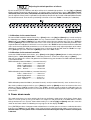
Default settings
Press [Enter] to reset all fixture personalities (not the adjusting functions) to the default values. On the display will
appear "rSt" meaning that the fixture makes the reset. See the table of personality settings and their default
values.
Personality
Display
Default values
(SHADED)
Pan reverse
Tilt reverse
DMX presetting
Lamp On after switch.
the fixture On
Lamp Off via DMX
Lamp On if DMX
is present
Lamp Off if DMX
is missing
Blackout during
mov. correction
Display-permanent
On
Display intensity
Display- reverse
PAN/TILT feedback
Switch On/Off
the lamp light sensor
Fan speed
operating modes
Blackout while
pan/tilt moving
Blackout while
colour wheel moving
Blackout while gobo
wheel moving
Pan/tilt mode
Music trigger
Microphone
sensitivity
29
8.5 Switching On/Off the lamp
Press the [Mode] button in order to access the main menu. Browse through the menu by pressing the [Up] and
[Down] buttons until the display shows "LAMP". Confirm by pressing [Enter] button.
Use the [Up] and [Down] buttons to select "On" to switch On the lamp and "Off" to switch Off the lamp and
press [Enter] to confirm or [Mode] to cancel.
8.6 Manual mode
Select this menu to call up presetted positions of channel effects or direct control channel effects.
Presetted effects
Select this menu to call up presetted positions of channel effects.Use the [Up] and [Down] buttons to select
desired effect and press [Enter] to select presetted effect positions.
Manual control
Select this menu in order to control fixture channels using control buttons on the control board.Use the [Up] and
[Down] buttons to select desired effect and press [Enter] to set DMX value for this effect.
30
8.7 Test sequences
This function allows you to run a special demo-test sequences without an external controller, which will show you
some possibilities of using COLORSPOT 250 AT. Press [Up] and [Down] keys to select the "Mod1" or "Mod2"
sequences. The "Mod1" is suitable for projections on the wall, ceiling or ground without any head-movement, the
"Mod2" uses all COLORSPOT 250 AT functions and therefore is good for a complete introduction of the fixture.Select
"Mod1" or "Mod2" by [Up] and [Down] buttons and press [Enter] to confirm the choice.If the test program is
running,messages "run/test" blink on the display.
If you want to pause the runnnig program in the required position, press the [Enter]-button(messages"PAUS"/"
test" blink ).To continue the program running,press the [Enter]-button again.
8.8 Stand-alone setting
This menu offers options for stand-alone mode as a selection of the playing program,programming and modifying
current programs.
- Music trigger
The COLORSPOT 250 AT enables the sound control of the running programs via the built-in microphone.Use the
[ Up ] or [ Down ] buttons to select "On" if you wish this feature or "Off" if you don’t wish this feature and press
[Enter ] to confirm or [ Mode ] to cancel and return to the menu.
31
Presetting playback
This function allows you to select the the program which will be played in the stand-alone mode after switching
the fixture On.Use the [Up] and [Down] buttons to select desired program ("tESt"- bilt-in program) or "OFF" if you
don't want trigger any program after switching the fixture On and press [Enter] to confirm or [Mode] to cancel and
return to the menu.Selected program will be played continuously in a loop as long as it appears on the display.
This option should be set "OFF" for all slaves in the master/slave chain by reason of the right program starts.
For example: You have selected program "PrG.3" in this menu and:
this fixture is set as a single fixture (master/slave or controller operating)- the fixture will run its program "PrG.3".
this fixture is set as a master in a data chain- the fixture will run its program "PrG.3".
this fixture is set as a slave in a data chain- the fixture will run its program according to the master(if the master
runs its own program "PrG.1", the slave will run its own program "PrG.1"also).
Note:If the fixture operates in the controller mode ( DMX controller is connected) and any program from this menu
is selected ,in this case the fixture will not respond to the DMX controller after switching On and will play selected
program.
Playing program
This function allows you to run a bilt-in program "tESt" and the 3 freely-programmable programs
"PrG.1,PrG.2,PrG.3" .Press [Up] or [Down] buttons to select the desired program and press [Enter] to run the
program which will be played continuously in a loop.
If you want to pause the runnnig program in the required position, press the [Enter]-button(messages"PAUS"/"
program No."blink ).To continue the program running,press the [Enter]-button again.
Note:If the fixture operates in the controller mode ( DMX controller is connected) and any program from this
function is selected in this case the fixture will not respond to the DMX controller and will play selected program.
You can't play programs on the slave fixtures from their control panels if the master fixture is switched On and
connected to the slaves (playing is forced by the master).
Editing program
This menu item allows you to select a program to edit or create.The COLORSPOT 250 AT has one built-in
program ("tESt") and the 3 free programs,each up to 99 steps.
If the fixture is set as a master ,then you may edit any program in the slaves.You can't edit programs on the slave
fixtures from their control panels if the master fixture is switched on and connected to the slaves (editing is
possible by the master control panel only).
Procedure:
1. Press [Up] or [Down]-button to select the program you want to edit ("PrG.1" - "PrG.3") and press [Enter].
2. Press [Up] or [Down]-button to select the desired fixture ("MASt." - "SLA.9") and press [Enter]-button.
3. Press [Up] or [Down]-button to select the desired program step ("St.01" - "St.99") and press [Enter]-button.
4 Press [Up] or [Down]-button to select the desired item and press [Enter]-button.Now you can edit by [Up] or
[Down] buttons the DMX value for selected item:
"P.End." - a total number of the program steps,value 1-99.This value you must set before start
programming(e.g. if you want to create program with the 10 steps,set the value onto 10).
"PAn" a pan,value 0-255
"Tilt" a tilt, value 0-255
"SPEd" - a speed of PAN/TILT movement,value 0-255
"P.t.SE." - a pan/tilt macro selection, value 0-255
"P.t.SP." - a pan/tilt macro speed, value 0-255
"Colo" a colour wheel, value 0-255
"F.Col" - a colour wheel fine, value 0-255
"Pris" a prism,macros,value 0-255
"P.rot" a prism rotation,value 0-255
"r.Gob." - a rot.gobo,value 0-255
"G.rot." - a rot. gobo rotation,value 0-255
"F.G.ro." - a rot. gobo rotation fine,value 0-255
32
a focus ,value 0-255
a focus fine ,value 0-255
a strobe,value 0-255
a dimmer, value 0-255
a dimmer fine, value 0-255
a step time,value 0,1-25,5 seconds
a copying the current prog. step to the next prog. step .If the last prog.step is copied to the
next prog. step ,parameter "P.End" is increased about one by itself (except step 99).
5. Press Enter]-button to confirm adjusted value .
6. Press [Mode]-button,select next prog. step and repeat this procedure (steps 4 and 6).
"Foc." "F.Foc." "Stro." "dimr" "F.dim." "S.tim." "COPY." -
8.9 Reset function
Press [Enter] button to run a reset. This option enables the COLORSPOT 250 AT to index all effects (functions)
and return to their standard positions.
8.10 Special functions
Use the [Up] and [Down] buttons to browse through the special functions and select the one by pressing [Enter].
Lamp adjustment
This function can be used when you make the fine adjustment of the lamp.If you select "LAAd" pressing by
[Enter]-button ,all effects will be canceled,shutter will be opened and the dimmer intensity will be set onto 100%.By
using the options "PAn, tilt,Foc" you can focus the light on a flat surface (wall) and perform the fine lamp
adjustment.
Fixture code
The option contains identification hexadecimal code (0000-FFFF) for the fixture, which is used for the master/
slave operation.
33
Adjusting the default positions of effects
By this function you can calibrate and adjust effekts their standard/right positions. Use the [Up] and [Down]
buttons to browse through the adjusting menu - the display shows step by step these items: "PAn, FPAn,Tilt,Ftilt,
SPEd,PtSE,PtSP, Func,Colo, F.Col,rGOB, Grot,FGro,PriS,Prot, Foc,F.Fo, Stro, dimr,Fdim ,FCAL" by which
you can adjust the fixture to the required/desired position (0-255) before the function calibration(DMX controller
must be disconnected. Then when the positioning is finished use the last "F.CAL." function (fine calibration).
1. Calibration via the control board
Disconnect DMX controller from the fixture.Press [Enter] and use the [Up] and [Down] keys in order to display
the following items: "Colo, rGob,Grot,dimr" for very smooth function calibration. Select one of them, press
[Enter] and use the [Up] and [Down] keys in order to adjust their right value from 0 to 255. Then press [Enter] to
confirm or [Mode] to cancel and return to the menu. This can be repeated for each calibration parameter if it is
required. When the calibration is finished, it is necessary to use the "ArES" function in order to write the calibration
values to the memory (EPROM) and to make a reset in order to check the newly adjusted positions of the colour,
gobo wheels and dimmer. When the reset of the fixture is finished, the display will show the "FCAL" message.
Press [Enter] to repeat the calibration or [Mode] to return to the "AdJ" menu.
2. Calibration via the external controller
Connect the DMX controller to the fixture, press [Enter] and the [Up] and [Down] buttons in order to display the
following items: "Colo, rGob,Grot,dimr" - calibration parameters. Select one of them and press [Enter].
Now you can calibrate the colour, and gobo wheels and dimmer by your controller. The DMX calibration protocol
is described in below.
DMX calibration protocol for Mode 1 (18 control channels):
"Colo."- Colour wheel..............channel 19
"rGob" - R.gobo wheel.............channel 20
"G.rot"- Gobo rotation.............channel 21
"dimr" - Dimmer......................channel 22
DMX calibration protocol for Mode 2 (14 control channels):
"Colo."- Colour wheel..............channel 15
"rGob" R.gobo wheel...............channel 16
"G.rot"-Gobo rotation..............channel 17
"dimr" - Dimmer......................channel 18
DMX calibration protocol for Mode 3 (20 control channels) and 4(16 control channels) starts at channel 21 (17)
After having calibrated required effects, press [Enter] to confirm (or [Mode] to cancel and return to the menu
without reset by the "A.rES." function) and use the "A.rES." function in order to write the calibration values to
the memory (EEPROM) and to make a reset in order to check the new adjusted positions of the colour, gobo and
effect wheels .
9. Power down mode
This mode omits fixture reset after switching the fixture on and lowers motor powers of the fixture."Power down
mode" is useful in special casech.g. if the fixture is in a flight case and you want to set its DMX address without
taking it out from the case.To enter "Power down mode",press and hold [Up] and [Down] and at the same time
switch on the Power switch.The following message appears on the display:"P.d.Mo."
Press [ENTER] to activate "Low power mode" without fixture reset.Now you can set features and behaviour of the
fixture by using "A001"menu and "Pers." menu.If you want to go "normal operation mode",execute fixture reset.
Note:All motors in "Low power mode" are deactivated and switching the lamp on from the control panel
is blocked.
34
10. Error and information messages
HEAt
This message appears if you try to switch on the lamp within 5 minutes after having switched it off (the lamp is too
hot). The message will appear on the display if the lamp doesn't ignite within 28 seconds. The COLORSPOT 250
AT will store this information and automatically ignite the lamp when the 5 minutes period has expired.
Caution: The message is disabled if the lamp light sensor (function "En.Sn.") is switched Off (only if the lamp
was turned Off and On within 5 minutes,the message "HEAt" will appear).
LA.Er.
The ignition of the lamp is seven times unsuccessful (the "HEAt" message appeared six times before), and the
display shows "LA.Er", meaning that the lamp could be damaged or even missed, the fixture is overheating (this
can occur if the ambient temperature is 45° C or more) or there could be a failure on the ignitor or ballast.
Please place or replace the lamp, check the ambient temperature or contact your dealer if the situation was not
caused by the lamp.
Caution: The message is disabled if the lamp light sensor (function "En.Sn.") is switched Off.
FAn
The message informs you that the fixture was overheating and switched off. This message will appear on the
display if the fan speed mode "LOOF" was operated.
M.b.Er.
This messsage informs you that the main PCB does not communicate correctly with the Control Panel.
Co.Er. (color-wheel error)
The messsage will appear after the reset of the fixture if the magnetic-indexing circuit malfunctions (sensor failed
or magnet missing) or the stepping-motor is defective (or its driver circuit on the main PCB). The color-wheel is not
located in the default position after the reset.
r.G.Er.(rotating gobo-wheel error)
This message will appear after the reset of the fixture if the magnetic-indexing circuit malfunctions (sensor failed
or magnet missing) or the stepping-motor is defective (or its driver circuit on the main PCB). The rotating gobowheel is not located in the default position after the reset.
I.G.Er. (rotating gobo indexing error)
The message will appear after the reset of the fixture and if the magnetic-indexing circuit malfunctions (sensor
failed or magnet missing) or the stepping-motor is defective (or its driver circuit on the main PCB). The rotating
gobo is not located in the default position after the reset.
F.tEr.
The message informs you that the fixture was overheating (occured if the ambient temperature is 45° C or more)
and that the relay switched off the lamp. This message will appear on the display until the temperature will be on
a suitable level, then the display will show the "HEAt" message meaning the lamp is too hot.
SnEr.
This message appears if the lamp lighting sensor is failed. Please, contact your dealer.
Caution: The message is disabled if the lamp light sensor (function "En.Sn.") is switched Off.
Po.Er.
This message will appear if the fixture was shortly disconnect from the main.
PA.Er.(Pan-yoke movement error)
This message will appear after the reset of the fixture if the yoke’s magnetic-indexing circuits malfunction (sensors
failed or magnet missing) or the stepping motor is defective. (Or its driving IC on the main PCB). The yoke is not
located in the default position after the reset.
ti.Er.(TILT-head movement error)
This message will appear after the reset of the fixture if the head’s magnetic-indexing circuit malfunctions (sensor
failed or magnet missing) or the stepping motor is defective. (Or its driving IC on the main PCB). The head is not
located in the default position after the reset.
35
MA.Er.(Master error)
The message informs you that the fixture was addressed as a master and DMX signal is connected to its
input.Disconnect the DMX controller from fixture's input and address the fixture as the master again.
Fr.Er.
It will appear if the frequency of the mains is not standard 50 or 60Hz.
36
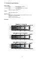
11. Technical specifications
Power supply:
EU-model-Voltage......................208/230/240V AC, 50/60 Hz ~
-Fuse.........................T 3.15 A@230V
US-model-Voltage......................100/120/208/230/240 V AC, 50/60 Hz ~
-Fuse.........................T 6.3 A@120V
-Power consumption....410 VA
Lamps:
-Philips MSD 250W/2 GY9.5
Optical system:
-High luminous-efficiency parabolic mirror and double condenser system
-Standard 15° focused beam angle
-Optional 12° and 18° lenses
-All lenses are anti-reflection coated
Beampath:
37
Colours-wheel:
- 10 dichroic-filters plus white
- Colour-wheel with variable rotation speed
- All colours are easily replaceable
Rotating gobos-wheel:
- 6 dichroic glass gobos and one glass gobo rotating in both directions at different speeds
- Gobo indexing
- Rotating gobo-wheel cont. rotation
- Multicolor dichroic glass gobos:outside diameter=26.8mm,thickness=1.1mm,high temperature
borofloat or better glass,image diameter=22 mm
-Glass gobo:outside diameter=26.8mm,max.thickness=4mm,high temperature borofloat or better
glass
- All rotating gobos are easily replaceable
Strobe:
-Strobe effect with variable speed ( 1 - 15 flashes per second)
-Preprogrammed variable/random strobe and dimmer pulse-effects
Dimmer:
-Smooth dimmer from 0 - 100 %
Prism:
-3-facet-prism rotating in both directions at different speeds
-Macro-function for rotating gobos/rotating prism combinations
-Prism can be replace by frost filter
Focus:
-Remotely controllable motorized focus from near to far
Motors:
-10 high quality stepping motors controlled by microprocessors
Electronics:
-Addressing,special functions setting,effects calibration via control panel with 4-digit LED display
-Readout fixture and lamp usage,receiving DMX values,temperature, etc
-Built-in analyzer for easy fault finding,error messages
-Remotely switching of the lamp
-Bilt-in demo sequences
-Black-out while head moving or gobo/colour changing
-Silent fans cooling
-Self-resetable thermo-fuse
-Digital serial input DMX-512
-Master/slave operation (up to 9 slaves)
-DMX-control via every standard DMX controller
- 4 control-channels presettings (14,16,18,20 control channels)
Pan/Tilt
-Pan movement range 530°
-Tilt movement range 280°
-16 bit movement resolution
-Automatic Pan / Tilt position correction
-Remotely controllable speed of Pan/Tilt movement for easy programming
-Max.Pan speed 184.67°/sec.
-Max.Tilt speed 127.85°/sec.
38
Rigging
-Stands directly on the floor
-Mounts horizontally or vertically with 2 Omega holders
-2 truss orientation
-Safety chain/cord attachment point
Data input/output
- 3-pin and 5-pin XLR male sockets for DMX data input
- 3-pin and 5-pin XLR female sockets for DMX data output
Temperatures
-Maximum ambient temperature : 45° C
-Maximum housing temperature : 75° C
Minimum distances
-Min.distance from flammable surfaces: 0,5m
-Min.distance to lighted object: 1,3m
Dimensions(mm):
Weight (net):
EU version:20.5 kg
US version:23.5 kg
Accessories
- Accessories gobo-set 12................................15050021
- Omega holder (2 pieces)................................99010420
39
Optional accessories:
- Objective12°.........................................99010201
-Lens-module 18°...................................99010200
12. Maintenance and cleaning
It is absolutely essential that the fixture is kept clean and that dust, dirt and smoke-fluid residues must not build
up on or within the fixture. Otherwise, the fixture‘s light-output will be significantly reduced. Regular cleaning will
not only ensure the maximum light-output, but will also allow the fixture to function reliably throughout its life.
A soft lint-free cloth moistened with any good glass cleaning fluid is recommended, under no circumstances
should alcohol or solvents be used!
DANGER !
Disconnect from the mains before starting any
maintenance work
The front objective lens will require weekly cleaning as smoke-fluid tends to building up residues, reducing the
light-output very quickly. The cooling-fans should be cleaned monthly.
The gobos may be cleaned with a soft brush. The interior of the fixture should be cleaned at least annually using
a vacuum-cleaner or an air-jet.
The dichroic colour-filters, the gobo-wheel and the internal lenses should be cleaned monthly.
There are no serviceable parts inside the device except for the lamp and the fuse.
Please refer to the instructions under "Fitting/Exchanging the lamp".
More complicated maintenance and service operations are only to be carried out by authorized dealers.
Replacing the fuse
If the lamp burns out, the fine-wire fuse of the device might fuse, too. Only replace the fuse by a fuse of same type
and rating.
Before replacing the fuse, unplug mains lead.
Procedure:
1) Unscrew the fuseholder on the rear panel of the base with a fitting screwdriver from the housing (anticlockwise).
2) Remove the old fuse from the fuseholder.
3) Install the new fuse in the fuseholder.
4) Replace the fuseholder in the housing and fix it.
40
41