1
T67xx C02 Sensor Module
Application Note
APPLICATION NOTE
APPLICATION NOTE FOR T67XX SERIES
CO2 SENSOR
REVISION RECORD
REVISION
ORIGINATOR
1
Norman Hannotte
Description of changes
- Initial Document release
DATE JUL.1.2014
REV.2
PAGE 2 OF 30
RELEASED
Feb.19.2014
REVISION
ORIGINATOR
RELEASED
2
Norman Hannotte
July.1.2014
Description of changes
- Correction to I2C pin-out
- Added example code, customer support sections
- Add details of ABC Logic™ on/off
- Added detail to installation / mounting section
- Addition of Operation details, safety, conversion of PWM to analog signal sections
- Remove watermark and preliminary markings
APPLICATION NOTE
APPLICATION NOTE FOR T67XX SERIES
CO2 SENSOR
DATE JUL.1.2014
REV.2
PAGE 3 OF 30
Table of Contents
1
Preamble.............................................................................................................................. 4
2
Interface Connector .............................................................................................................. 4
3
Communication – Modbus Protocol ...................................................................................... 7
3.1
UART (RS232/RS485) .................................................................................................. 7
3.2
I2C ................................................................................................................................. 7
4
Specification......................................................................................................................... 8
5
Installation / Mounting .......................................................................................................... 8
5.1
Design considerations ................................................................................................... 8
5.2
Installation ..................................................................................................................... 8
5.3
ESD Precautions ........................................................................................................... 8
6
Operation details .................................................................................................................. 9
6.1
ABC Logic™ ................................................................................................................. 9
6.2
Environmental ............................................................................................................... 9
6.3
Absolute Maximum Ratings........................................................................................... 9
6.4
Power-On Sequence ..................................................................................................... 9
6.5
Power Supply Requirements ......................................................................................... 9
6.6
Evaluation / Demonstration Kits .................................................................................. 10
7
PWM Output ...................................................................................................................... 10
8
Safety................................................................................................................................. 12
8.1
Disclaimer ................................................................................................................... 12
8.2
Safety While In Use..................................................................................................... 12
8.3
Material Contents ........................................................................................................ 13
9
Command Summary .......................................................................................................... 13
9.1
FIRMWARE REVISION............................................................................................... 14
9.2
STATUS ...................................................................................................................... 16
9.3
GAS PPM ................................................................................................................... 18
9.4
RESET DEVICE .......................................................................................................... 20
9.5
START SINGLE POINT CALIBRATION ...................................................................... 21
9.6
CHANGE SLAVE ADDRESS ...................................................................................... 24
9.7
ABC LOGIC™ ENABLE / DISABLE ............................................................................ 25
10
Example Code ................................................................................................................ 27
11
Customer Support Details ............................................................................................... 29
APPLICATION NOTE
APPLICATION NOTE FOR T67XX SERIES
CO2 SENSOR
DATE JUL.1.2014
REV.2
PAGE 4 OF 30
1 PREAMBLE
The purpose of this document is to outline the required interface design and communication
protocol for the T67xx CO2 Sensor. The intended audience is any developer who wishes to
query the sensor for information utilizing either the I2C, PWM or UART interfaces.
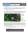
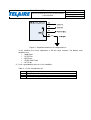
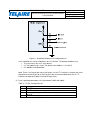
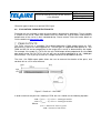
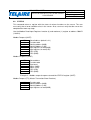
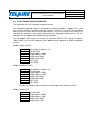
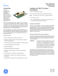
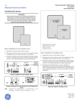
2 INTERFACE CONNECTOR
The six pin through hole connector on the PCB is were power and IO for the sensor are located,
see Figure 1 below. A six pin, 0.1” header must be installed in order to connect the sensor to a
controller. There are several different I/O configurations that are supported by the sensor, and
are determined by the voltage that is measured on pin 6 of the connector at startup.
1. TX / SDA
2. RX / SCL
3. V++
4. GND
5. PWM
6. CTRL / TEST
Figure 1 - T67XX Interface Connector
Note: Precautions should be taken to observe specified limits and prevent damage from
electrostatic discharge or rough handling. Please refer to ANSI/ESD S20. 20-1999 for more
information on preventing ESD damage and IPC 610 Rev D for more information on proper
electronic assembly practices. In addition to this, the sensor does not have internal reverse
polarity protection. Care should be taken to connect the sensor to the controller in the correct
wiring configuration to avoid damage.
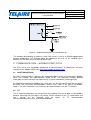
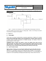
1) Pin 6 is left unconnected by the user and will therefore be left floating. It will be pulled up
by an internal 1MΩ resistor. In this condition;
Table 1 – I/O Pin Configuration #1
Pin
1
2
5
Description
UART TX (output from sensor)
UART Rx (input to sensor)
PWM output at approximately 1Hz
APPLICATION NOTE
APPLICATION NOTE FOR T67XX SERIES
CO2 SENSOR
DATE JUL.1.2014
REV.2
PAGE 5 OF 30
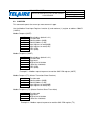
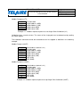
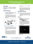
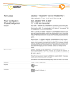
Figure 2 - Simplified Schematic I/O configuration #1
In this condition the sensor implements a RS-232 serial interface. The default serial
conditions are;
• 19200 Baud
• 1 START bit
• 8 DATA bits
• 1 EVEN PARITY bit
• 1 STOP bit
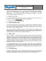
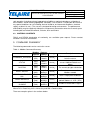
2) Pin 6 is grounded by the user. In this condition;
Table 2 - I/O Pin Configuration #2
Pin
1
2
5
Description
I2C SDA (Serial Data Line)
I2C SCL (Serial Clock Line)
PWM output at approximately 25kHz
APPLICATION NOTE
APPLICATION NOTE FOR T67XX SERIES
CO2 SENSOR
DATE JUL.1.2014
REV.2
PAGE 6 OF 30
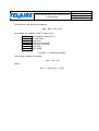
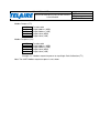
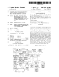
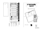
Figure 3 - Simplified Schematic I/O configuration #2
In this condition the sensor implements an I2C interface. The default conditions are;
• The sensor only acts as a slave device
• I2C 7-bit addressing is used. The default slave address is 21 (0x15)
• I2C 100kbit/s Standard Mode
Note: There is an internal pull up resistor on pin 1 of the I2C interface. Customer will need
to provide an external pull up resistor on pin 2 with a recommended value of 4.7k. I2C
interface can operate at both 3.3V and 5V logic levels.
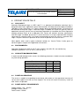
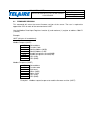
3) Pin 6 is pulled to ground by a resistor between 10kΩ and 100kΩ
Table 3 - I/O Pin Configuration #3
Pin
1
2
5
6
Description
UART TX (output from sensor)
UART Rx (input to sensor)
Becomes a test input for Telaire and should be left unconnected by
the user
Becomes an output pin used to drive an RS485 transceiver
APPLICATION NOTE
APPLICATION NOTE FOR T67XX SERIES
CO2 SENSOR
DATE JUL.1.2014
REV.2
PAGE 7 OF 30
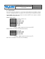
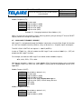
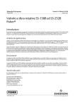
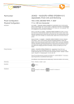
Figure 4 - Simplified Schematic I/O Configuration #3
The condition described by (3) above is useful if the sensor is used in an RS485 dropped node
network configuration. This network would be supplied by the user. In this condition pin 6
becomes the RS-485 transceiver data-direction logic.
3 COMMUNICATION – MODBUS PROTOCOL
The T67xx sensor uses the Modbus protocol for all communications. The documents are freely
available on the Modbus WEB site at http://www.modbus.org/specs.php.
3.1
UART (RS232/RS485)
For UART communications, reference the recommendations found in the document ‘Modbus
Serial Line Protocol and Implementation Guide V1.02’. This document includes detailed
information on how to calculate the required CRC (Cyclical Redundancy Checking) bytes.
It is important to note that for Modbus over serial lines (i.e., RS-232 and RS-485) the user MUST
INCLUDE THE CYCLICAL REDUNDANCY CHECK (CRC) fields at the end of the Modbus
request. The CRC calculation is not necessary for communications over the I2C interface.
3.2
I2C
The I2C implementation does not use the Serial Line protocol. The sensor does use the Modbus
protocol, and wraps the message in I2C format. Please reference to the “I2C specification and
user’s manual”
at
the
following
URL
for
details
on
I2C
communication
www.nxp.com/documents/user_manual/UM10204.pdf.
APPLICATION NOTE
APPLICATION NOTE FOR T67XX SERIES
CO2 SENSOR
DATE JUL.1.2014
REV.2
PAGE 8 OF 30
The sensor always operates as a slave. In the examples below the implementer using the I2C
interface will need communicate with the sensor as either a master-transmitter (for Modbus
requests) or a master-receiver (for Modbus responses). The sensor will not initiate
communications, i.e., it will not become a master and respond to the request. It is up to the
master to read the response from the sensor.
4 SPECIFICATION
All information about the performance of the sensor can be found on the website. Please refer to
the spec sheets found at www.telaire.com for the latest specifications.
5 INSTALLATION / MOUNTING
5.1
DESIGN CONSIDERATIONS
To maximize the performance of T67xx module, it is important to plan an appropriate location for
the sensor at the design stage. Airflow and proper exposure to ambient air must be secured for
T67xx module to ensure optimal performance. Inadequate airflow will deteriorate the response
time of the sensor. Also, avoid excess heat.
The sensor is designed for benign environments. The performance and reliability may be
negatively affected in environments that contain corrosive or caustic gases including but not
limited to Ammonia, Chlorine, NOx and Ozone. Care must be taken to ensure that the sensor is
not exposed to these compounds under any operating condition
5.2
INSTALLATION
The T67xx module is a sensitive electronics assembly, so effort should be made to minimize
exposure to excess heat from any type of soldering operation. Excess exposure to heat from
installation is known to create small shift in calibration of the sensor. Although the ABC Logic™
algorithm will correct these minor fluctuations within the first 24 hours of operation, the user
should minimize overexposure to heat when soldering to negate unexpected operation after
installation. Typically, an expose of not more than 10 sec. using a soldering iron set to 750°F
(400°C) will minimize the influence of heat on the measurement of the T67xx module. The use of
low temperature solder is also recommended.
It is recommended to handle the sensor by the edges of the PCBA. Any stress applied to the
PCB or the gold OBA assembly can cause mechanical stress that will create temporary shift in
the calibration of the sensor. Although he ABC Logic™ algorithm will correct for these shifts in
the first 24 hours of operation, extra care in handling will minimize the risk of variations that can
be seen out of the box.
5.3
ESD PRECAUTIONS
Precautions should be taken to observe specified limits and prevent damage from electrostatic
discharge or rough handling. Please refer to ANSI/ESD S20. 20-1999 for more information on
preventing ESD damage for more information on proper electronic assembly practices.
APPLICATION NOTE
APPLICATION NOTE FOR T67XX SERIES
CO2 SENSOR
DATE JUL.1.2014
REV.2
PAGE 9 OF 30
6 OPERATION DETAILS
6.1 ABC LOGIC™
Automatic Background Logic, or ABC Logic™, is a patented self-calibration technique that is
designed to be used in applications where concentrations will drop to outside ambient conditions
(400 ppm) at least three times in a 7 days, typically during unoccupied periods. Full accuracy to
be achieved utilizing ABC Logic™. With ABC Logic™ enabled, the sensor will typically reach its
operational accuracy after 24 hours of continuous operation at a condition that it was exposed to
ambient reference levels of air at 400 ppm CO2. Sensor will maintain accuracy specifications
with ABC Logic™ enabled, given that it is at least four times in 21 days exposed to the reference
value and this reference value is the lowest concentration to which the sensor is exposed. ABC
Logic™ requires continuous operation of the sensor for periods of at least 24 hours.
Note: Applies when used in typical residential ambient air. Consult Telaire if other gases or
corrosive agents are part of the application environment.
6.2
ENVIRONMENTAL
Operating Temperature: 50°F to 122°F (10°C to 50°C), 0 to 95% RH, non-condensing
Storage Temperature: -22°F to 158°F (-30°C to 70°C)
6.3
ABSOLUTE MAXIMUM RATINGS
In order to avoid damage to the sensor, the following parameters should never be exceeded at
any time during operation:
Parameter
Supply Voltage (V+, pin 3)
Ground (V-, pin 4)
TX / SDA, RX / SCL (pin 1,2)
MD DIR / PWM (pin 5)
UART/I2C Select (pin 6)
6.4
Min (V)
-0.3
-0.3
-0.3
-0.3
-0.3
Max (V)
7
0.3
7
7
3
POWER-ON SEQUENCE
The sensor is capable of responding to commands after power on, but operational accuracy of
sensor won’t happen until 120 sec have elapsed. The sensor will reach full accuracy / warm up
after 10 min. of operation.
6.5
POWER SUPPLY REQUIREMENTS
Supply Voltage: +4.5 – 5.5VDC
Average Current*: 20mA
Peak Current*: 155mA
APPLICATION NOTE
APPLICATION NOTE FOR T67XX SERIES
CO2 SENSOR
DATE JUL.1.2014
REV.2
PAGE 10 OF 30
*Based on typical values at a nominal 5VDC input
6.6
EVALUATION / DEMONSTRATION KITS
Evaluation kits are available in order to help customers develop their application. The kit includes
a sample of the sensor, cable and software that will enable the user to better understand the
performance of the sensor in their intended design. Please contact Telaire for further details or
visit the website at www.telaire.com.
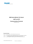
7 PWM OUTPUTS
The T67xx sensor has a selectable Pulse Width Modulation (PWM) output feature on Pin5,
based on the state of Pin 6 during power on. The two types of supported PWM operate at ~1Hz
PWM and 25k Hz and are proportional to the range of the sensor as determined by the model.
For example, if the model is a T6713-5k, the units PWM output will be proportional to a 0 to 5000
ppm output range. For PN T6713, the unit will have an output proportional to a 0 – 2000 ppm
measurement. A 4.7K pull up resistor to a voltage reference can be added if desired.
The slow ~1Hz PWM output option allows the user to measure the duration of the pulse, and
correlate this to a CO2 measurements.
Start
End
high
low
Figure 5 - Details of ~1Hz PWM
In order to convert the pulse to a reading in PPM, the user should use the following equation:
2 ∗ 2for0– 2000ppmmodels
2 ∗ 5for0– 5000ppmmodels
Where:
!" # $%& #
!'() * #
APPLICATION NOTE
APPLICATION NOTE FOR T67XX SERIES
CO2 SENSOR
Figure 6 - Example of the PWM for -2K model
DATE JUL.1.2014
REV.2
PAGE 11 OF 30
APPLICATION NOTE
APPLICATION NOTE FOR T67XX SERIES
CO2 SENSOR
DATE JUL.1.2014
REV.2
PAGE 12 OF 30
Potential circuit design to convert 25 kHz PWM to an analog output for I/O configuration # 2 (I2C,
PWM at 25 kHz):
Figure 7 - Potential Circuit Design for 25 kHz PWM output to Analog Signal Conversion
The 25 kHz PWM can be filtered to create an analog output. Above is one filtering circuit where
R3 and R4 will set the gain of the amplifier.
8 SAFETY
8.1
DISCLAIMER
Telaire makes no warranty, representation or guarantee regarding the suitability of this product
for any particular application, including safety critical applications. Nor does Telaire assume any
liability arising out of the application or use in any product or circuit. Telaire specifically disclaims
all liability without limitation consequential or incidental damages. No statuary or fitness for
particular purpose shall be implied.
WARNING! Before installing the product, review the product data sheet and this
application guide. The product shall be used only within power supply and electrical input
and output limits as specified by the datasheet and application guide. Improper use of the
product may result in product damage and property loss and/or personal injury.
8.2
SAFETY WHILE IN USE
Before installing, handling, using, or servicing this product, please consult the data sheet and
application notes. The product shall be used only within power supply and electrical input and
output limits as specified by the datasheet and application guide. Improper use of the product
may result in product damage and property loss and/or personal injury. In use of the product, the
customer has sole responsibility for designing and implementing a solution which will ensure
APPLICATION NOTE
APPLICATION NOTE FOR T67XX SERIES
CO2 SENSOR
DATE JUL.1.2014
REV.2
PAGE 13 OF 30
safe operation (including review of appropriate reliability or required redundancy, mitigation of
failure modes, and/or meeting appropriate standards). The customer is responsible for review of
any special conditions for use including, but not limited to, environmental conditions, electrical
supply, residual risk, etc.). The sensor is designed for benign environments. The performance
and reliability may be negatively affected in environments that contain corrosive or caustic gases
including but not limited to Ammonia, Chlorine, NOx and Ozone.
8.3
MATERIAL CONTENTS
ROHS and REACH declaration of conformity are available upon request. Please contact
customer service for more details.
9 COMMAND SUMMARY
The following commands can be sent to the sensor.
Table 4 - Modbus Command Summary
Name
FIRMWARE_REVISION
Modbus Register
Register Address
Input
‘5001’D
(RO)
‘1389’H
Data type
uint16_t
Description
Returns the firmware revision
from the sensor
Returns a status register from the
sensor. Additional details are
below
STATUS
Input
(RO)
‘5002’D
‘138A’H
uint16_t
GAS PPM
Input
(RO)
‘5003’D
‘138B’H
uint16_t
The current gas ppm calculation
RESET DEVICE
Coils
(WO)
‘1000’D
‘03E8’H
uint16_t
Reset the sensor over the
Modbus network
Coils
(WO)
Holding
(RW)
‘1004’D
‘03EC’H
‘4005’D
‘0FA5’H
uint16_t
Start a single-point calibration
uin16_t
Change of sensor address
(default address is ‘21’D (‘15’H)
Coils
(RW)
‘1006’D
‘03EE’H
uin16_t
Enable or disable ABC Logic™
START SINGLE POINT
CAL
SLAVE ADDRESS
ABC LOGIC™ ENABLE
/ DISABLE
Where RO is Read Only, WO is Write Only and RW is Read or Write.
There are examples given in the sections below.
APPLICATION NOTE
APPLICATION NOTE FOR T67XX SERIES
CO2 SENSOR
9.1
DATE JUL.1.2014
REV.2
PAGE 14 OF 30
FIRMWARE REVISION
This command will return the current firmware revision of the sensor. The user is required to
append the CRC for each of the command over UART.
Use the Modbus Read Input Registers function (4) and read one (1) register at address ‘5001’D
(‘1389’H).
Example:
UART (all bytes in hexadecimal)
Modbus Request (UART)
‘15’H
‘04’H
‘13’H
‘89’H
‘00’H
‘01’H
xx
xx
Slave address
Function Code
Starting Address (MSB)
Starting Address (LSB)
Number of registers to read (MSB)
Number of registers to read (LSB)
CRC (LSB)
CRC (MSB)
Modbus Response (UART)
‘15’H
‘04’H
‘02’H
xx
xx
xx
xx
Slave address
Function code
Byte count
Status (MSB)
Status (LSB)
CRC (LSB)
CRC (MSB)
Example 1 - Modbus request/response to read the firmware revision (UART)
APPLICATION NOTE
APPLICATION NOTE FOR T67XX SERIES
CO2 SENSOR
DATE JUL.1.2014
REV.2
PAGE 15 OF 30
I2C (all bytes in hexadecimal)
The default I2C slave address is ‘21’D (‘15’H) and not shown.
Modbus Request (Master-Transmitter/Slave-Receiver)
‘04’H
‘13’H
‘89’H
‘00’H
‘01’H
Function Code
Starting Address (MSB)
Starting Address (LSB)
Number of registers to read (MSB)
Number of registers to read (LSB)
Modbus Response (Master-Receiver/Slave-Transmitter)
‘04’H
‘02’H
xx
xx
Function code
Byte count
status (MSB)
status (LSB)
Example 2 - Modbus request/response to read the firmware revision (I2C)
It is important to note that the sensor is a slave device only. The user must implement a master
I2C device to facilitate reading and writing to the sensor.
APPLICATION NOTE
APPLICATION NOTE FOR T67XX SERIES
CO2 SENSOR
9.2
DATE JUL.1.2014
REV.2
PAGE 16 OF 30
STATUS
This command returns a register with the status of various functions on the sensor. The user
must verify that no error condition exists in the sensor. Also, user must verify that the sensor has
completed the warm-up stage.
Use the Modbus Read Input Registers function (4) and read one (1) register at address ‘5002’D
(‘138A’H).
Modbus Request (UART)
‘15’H
‘04’H
‘13’H
‘8A’H
‘00’H
‘01’H
xx
xx
Slave Address (default is 21)
Function code
Starting address (MSB)
Starting Address (LSB)
Input registers to read (MSB)
Input registers to read (LSB)
CRC (LSB)
CRC (MSB)
Modbus Response (UART)
‘15’H
‘04’H
‘02’H
xx
xx
xx
xx
Slave address
Function code
Byte count
Status (MSB)
Status (LSB)
CRC (LSB)
CRC (MSB)
Example 3 – Modbus request/response to read the STATUS register (UART)
Modbus Request (I2C) (Master-Transmitter/Slave-Receiver)
‘04’H
‘13’H
‘8A’H
‘00’H
Function code
Starting address (MSB)
Starting Address (LSB)
Input registers to read (MSB)
APPLICATION NOTE
APPLICATION NOTE FOR T67XX SERIES
CO2 SENSOR
DATE JUL.1.2014
REV.2
PAGE 17 OF 30
Modbus Response (I2C) (Master-Receiver/Slave-Transmitter)
‘04’H
‘02’H
xx
xx
Function code
Byte count
Status (MSB)
Status (LSB)
Example 4 – Modbus request/response to read the STATUS register (I2C)
The STATUS register is a bit-vector where each bit represents the status of some function within
the sensor. Not all bits are assigned.
Bit position
xxxxxxxx, xxxxxxx1
xxxxxxxx, xxxxxx1x
xxxxxxxx, xxxxx1xx
xxxxxxxx, xxxx1xxx
xxxxxxxx, xxx1xxxx
xxxxxxxx, xx1xxxxx
xxxxxxxx, x1xxxxxx
xxxxxxxx, 1xxxxxxx
xxxxxxx1, xxxxxxxx
xxxxxx1x, xxxxxxxx
xxxxx1xx, xxxxxxxx
xxxx1xxx, xxxxxxxx
xxx1xxxx, xxxxxxxx
xx1xxxxx, xxxxxxxx
x1xxxxxx, xxxxxxxx
1xxxxxxx, xxxxxxxx
HEX
‘0001’H
‘0002’H
‘0004’H
‘0008’H
‘0010’H
‘0020’H
‘0040’H
‘0080’H
‘0100’H
‘0200’H
‘0400’H
‘0800’H
‘1000’H
‘2000’H
‘4000’H
‘8000’H
Comments
Error condition
Flash error
Calibration error
NA
NA
NA
NA
NA
RS-232
RS-485
I2C
Warm-up mode
NA
NA
NA
Single point calibration
For error conditions, a '1' indicates an error; a '0' indicates no error. Flash error is fatal (i.e., there
is no recovery). Calibration errors can be cleared by running the calibration procedure again with
successful results.
For calibration conditions, a '1' indicates that the calibration cycle is currently in progress. No
other calibration cycle can start while one is currently in progress and will result in an error being
reported by the Modbus response to the new calibration request.
If the Warm-up bit is set the sensor is in a mode where internal registers are being initialized and
gas (ppm) data is not necessarily correct.
APPLICATION NOTE
APPLICATION NOTE FOR T67XX SERIES
CO2 SENSOR
9.3
DATE JUL.1.2014
REV.2
PAGE 18 OF 30
GAS PPM
This command reports the current gas measurement in ppm.
Use the Modbus Read Input Registers function (4) and read one (1) register at address ‘5003’D
(‘138B’H).
Modbus Request (UART)
‘15’H
‘04’H
‘13’H
‘8B’H
‘00’H
‘01’H
xx
xx
Slave Address (default is 21)
Function code
Starting address (MSB)
Starting Address (LSB)
Input registers to read (MSB)
Input registers to read (LSB)
CRC (LSB)
CRC (MSB)
Modbus Response (UART)
‘15’H
‘04’H
‘02’H
xx
xx
xx
xx
Slave Address (default is 21)
Function code
Byte count
MSB of the 16-bit data
LSB of the 16-bit data
CRC (LSB)
CRC (MSB)
Example 5 – Modbus request/response to read the GAS PPM register (UART)
Modbus Request (I2C) (Master-Transmitter/Slave-Receiver)
‘04’H
‘13’H
‘8B’H
‘00’H
‘01’H
Function code
Starting address (MSB)
Starting Address (LSB)
Input registers to read (MSB)
Input registers to read (LSB)
Modbus Response (I2C) (Master-Receiver/Slave-Transmitter)
‘04’H
‘02’H
xx
xx
Function code
Byte count
MSB of the 16-bit data
LSB of the 16-bit data
Example 6 – Modbus request/response to read the GAS PPM register (I2C)
APPLICATION NOTE
APPLICATION NOTE FOR T67XX SERIES
CO2 SENSOR
To calculate the gas ppm do the following;
ppm = MSB * 256 + LSB
For example, if the Modbus (UART) response was
‘15’H
‘04’H
‘02’H
‘01’H
‘9F’H
xx
xx
Slave Address (default is 21)
Function code
Byte count
MSB of the 16-bit data
LSB of the 16-bit data
CRC (LSB)
CRC (MSB)
Example 7 – Calculating GAS ppm
Then the gas could be calculated as
1*256 + 159 = 415
Where
‘01’H = ‘1’D and ‘9F’H = ‘159’D
DATE JUL.1.2014
REV.2
PAGE 19 OF 30
APPLICATION NOTE
APPLICATION NOTE FOR T67XX SERIES
CO2 SENSOR
9.4
DATE JUL.1.2014
REV.2
PAGE 20 OF 30
RESET DEVICE
The sensor can be reset (though this is not normally recommended) over the Modbus interface.
The reset is immediate and there is no response. The sensor will act as if the power was cycled.
Use the Modbus Write Single Coil function (5) and write ‘00FF’H to the register at address
‘1000’D (03E8’H) to reset the sensor.
Modbus Request (UART)
‘15’H
‘05’H
‘03’H
‘E8’H
‘FF’H
‘00’H
xx
xx
Slave Address (default is 21)
Function code
Output address (MSB)
Output Address (LSB)
Output value (MSB)
Output value (LSB)
CRC (LSB)
CRC (MSB)
Example 8 - Modbus request to reset the sensor (UART)
Modbus Request (I2C) (Master-Transmitter/Slave-Receiver)
‘05’H
‘03’H
‘E8’H
‘FF’H
‘00’H
Function code
Output address (MSB)
Output Address (LSB)
Output value (MSB)
Output value (LSB)
Example 9 – Modbus request to reset the sensor (I2C)
Note: There is no response. The sensor resets immediately.
APPLICATION NOTE
APPLICATION NOTE FOR T67XX SERIES
CO2 SENSOR
9.5
DATE JUL.1.2014
REV.2
PAGE 21 OF 30
START SINGLE POINT CALIBRATION
This command starts the single point calibration routine.
The single-point calibration routine is usually done at ambient conditions (~500ppm, 25 °C) and
takes several minutes to complete after being started (~6 minutes). The sensor can be queried
during this time for status and current gas ppm readings. The user can check on the status of the
calibration by reading the status register and noting if the single-point calibration bit is set. The
calibration can be stopped before completing. See examples.
Use the Modbus Write Single Coil function (5) and write ‘00FF’H to the register at address
‘1004’D (03EC’H) to start the calibration. Write ‘0000’H during calibration to stop the calibration
function.
Modbus Request (UART)
‘15’H
‘05’H
‘03’H
‘EC’H
‘FF’H
‘00’H
xx
xx
Slave Address (default is 21)
Function code
Output address (MSB)
Output Address (LSB)
Output value (MSB)
Output value (LSB)
CRC (LSB)
CRC (MSB)
Modbus Response (UART)
‘15’H
‘05’H
‘03’H
‘EC’H
‘FF’H
‘00’H
xx
xx
Slave Address (default is 21)
Function code
Output address (MSB)
Output Address (LSB)
Output value (MSB)
Output value (LSB)
CRC (LSB)
CRC (MSB)
Example 10 - Modbus request/response to start Single Point Calibration (UART)
Modbus Request (I2C)
‘05’H
‘03’H
‘EC’H
‘FF’H
‘00’H
Function code
Output address (MSB)
Output Address (LSB)
Output value (MSB)
Output value (LSB)
APPLICATION NOTE
APPLICATION NOTE FOR T67XX SERIES
CO2 SENSOR
DATE JUL.1.2014
REV.2
PAGE 22 OF 30
Modbus Response (I2C)
‘05’H
‘03’H
‘EC’H
‘FF’H
‘00’H
Function code
Output address (MSB)
Output Address (LSB)
Output value (MSB)
Output value (LSB)
Example 11 – Modbus request/response to start Single Point Calibration (I2C)
Calibration takes several minutes. The status of the single point can be determined by reading
the status register.
The calibration command cannot be restarted but can be stopped as detailed in the following
example.
Modbus Request (UART)
‘15’H
‘05’H
‘03’H
‘EC’H
‘00’H
‘00’H
xx
xx
Slave Address (default is 21)
Function code
Output address (MSB)
Output Address (LSB)
Output value (MSB)
Output value (LSB)
CRC (LSB)
CRC (MSB)
Modbus Response (UART)
‘15’H
‘05’H
‘03’H
‘EC’H
‘00’H
‘00’H
xx
xx
Slave Address (default is 21)
Function code
Output address (MSB)
Output Address (LSB)
Output value (MSB)
Output value (LSB)
CRC (LSB)
CRC (MSB)
Example 12 – Modbus request/response to stop Single Point Calibration (UART)
APPLICATION NOTE
APPLICATION NOTE FOR T67XX SERIES
CO2 SENSOR
DATE JUL.1.2014
REV.2
PAGE 23 OF 30
Modbus Request (I2C)
‘05’H
‘03’H
‘EC’H
‘00’H
‘00’H
Function code
Output address (MSB)
Output Address (LSB)
Output value (MSB)
Output value (LSB)
Modbus Response (I2C)
‘05’H
‘03’H
‘EC’H
‘00’H
‘00’H
Function code
Output address (MSB)
Output Address (LSB)
Output value (MSB)
Output value (LSB)
Example 13 – Modbus request/response to stop Single Point Calibration (I2C)
Note: The UART Modbus request/response is not shown.
APPLICATION NOTE
APPLICATION NOTE FOR T67XX SERIES
CO2 SENSOR
9.6
DATE JUL.1.2014
REV.2
PAGE 24 OF 30
CHANGE SLAVE ADDRESS
It is possible to change the Modbus slave address. The change will only take effect after the
sensor has been reset (e.g., over the Modbus interface) or power cycled. The change does not
take effect immediately.
User the Modbus Write Single Register function (6) and write the new address to the register at
address ‘4005’D (‘0FA5’H).
This example changes the current slave address to ‘16’D (‘10’H).
Modbus Request (UART)
‘15’H
‘06’H
‘0F’H
‘A5’H
‘00’H
xx
xx
xx
Slave Address (default is 21)
Function code
Register address (MSB)
Register Address (LSB)
Register value (MSB) MSB will always be zero
Register value (LSB) LSB should be between 1-247
CRC (LSB)
CRC (MSB)
Modbus Response (UART)
‘15’H
‘06’H
‘0F’H
‘A5’H
‘00’H
xx
xx
xx
Slave Address (default is 21)
Function code
Register address (MSB)
Register Address (LSB)
Register value (MSB)
Register value (LSB)
CRC (LSB)
CRC (MSB)
Example 14 – Changing the default Slave Address (UART)
Modbus Request (I2C)
‘06’H
‘0F’H
‘A5’H
‘00’H
xx
Function code
Register address (MSB)
Register Address (LSB)
Register value (MSB) MSB will always be zero
Register value (LSB) LSB should be between 1-247
APPLICATION NOTE
APPLICATION NOTE FOR T67XX SERIES
CO2 SENSOR
DATE JUL.1.2014
REV.2
PAGE 25 OF 30
Modbus Response (I2C)
‘06’H
‘0F’H
‘A5’H
‘00’H
xx
Function code
Register address (MSB)
Register Address (LSB)
Register value (MSB)
Register value (LSB)
Example 15 – Changing the default Slave Address (I2C)
Note: It is necessary to restart the sensor, either by power cycling or writing ‘FF’H to the RESET
register, before this change will take effect.
9.7
ABC LOGIC™ ENABLE / DISABLE
ABC Logic™ is manipulated through the Modbus interface by using the Write Single Coil function
(5). Coils are viewed as basically switches, relays or discrete (i.e., single bit) inputs and outputs.
The ABC LOGIC CONTROL coil register is ‘1006’D (‘03EE’H).
A write of ‘FF00’H (i.e., ON) will enable the ABC Logic™ and a write of ‘0000’H (i.e., OFF) will
disable the ABC Logic™ function.
For example, to enable the ABC Logic™ one would send the Modbus request;
‘05’H, ‘03’H, ‘EE’H, ‘FF’H, ‘00’H
Note that the example is shown as a simple Modbus PDU. For communications over a serial port
(i.e., Modbus Serial Line PDU) the slave address would need to be prepended and the CRC
appended.
Modbus Request (UART)
‘15’H
‘05’H
‘03’H
‘EE’H
‘FF’H
‘00’H
xx
xx
Slave Address (default is 21)
Function code
Register address (MSB)
Register Address (LSB)
Register value (MSB) Enable ABC Logic™
Register value (LSB) LSB will always be zero
CRC (LSB)
CRC (MSB)
Modbus Response (UART)
‘15’H
‘05’H
‘03’H
Slave Address (default is 21)
Function code
Register address (MSB)
APPLICATION NOTE
APPLICATION NOTE FOR T67XX SERIES
CO2 SENSOR
‘EE’H
‘FF’H
‘00’H
xx
xx
Register Address (LSB)
Register value (MSB)
Register value (LSB)
CRC (LSB)
CRC (MSB)
Example 16 – Enable ABC Logic™ (UART)
Modbus Request (I2C)
‘05’H
‘03’H
‘EE’H
‘00’H
‘00’H
Function code
Register address (MSB)
Register Address (LSB)
Register value (MSB) Disable ABC Logic™
Register value (LSB) LSB will always be zero
Example 17 – Disable ABC Logic™ (I2C)
DATE JUL.1.2014
REV.2
PAGE 26 OF 30
APPLICATION NOTE
APPLICATION NOTE FOR T67XX SERIES
CO2 SENSOR
DATE JUL.1.2014
REV.2
PAGE 27 OF 30
10 EXAMPLE CODE
Reading Value for CO2
Reading the T67xx sensor in an embedded design is fairly easy. This example assumes that the
controlling micro-processor has already initialized a UART and the sensor has the default
settings from the factory (e.g., the slave address is 0x15).
Because the slave address and CRC will never change the programmer can just
defined the entire Modbus request as constants in as array.
For example;
static const uint8_t MOD_READ[] = {
0x15, /* slave address */
0x04, /* Modbus function: Read Input Registers */
0x13, /* Starting Address: 5003, MSB first */
0x8B,
0x00, /* # of registers to read: 1, MSB first */
0x01,
0x46, /* CRC, LSB then MSB */
0x70
};
The following example sends the above character array out the serial port and
then delays 50ms before looking for a response. The response should be 7 bytes
long and in this example will fill a data structure (i.e., char array) named
inBuf[] with the result.
inBuf[0] = 0x15
inBuf[1] = 0x04
inBuf[2] = 0x02
inBuf[3] = 0x??
inBuf[4] = 0x??
inBuf[5] = 0x??
inBuf[6] = 0x??
/* slave address */
/* function code */
/* byte count */
/* CO2 reading, MSB */
/* CO2 reading, LSB */
/* CRC, LSB */
/* CRC, MSB */
The CO2 can then be calculated by
inBuf[3] * 256 + inBuf[4]
The simplified code example follows;
/* Send the query string and delay for the data to come back */
write_uart1((void*)MOD_READ, 8);
delay(50);
/* look for a well formed response */
APPLICATION NOTE
APPLICATION NOTE FOR T67XX SERIES
CO2 SENSOR
if ( /* there are 7 bytes in the input buffer */)
{
read_uart1((void*)inBuf, 7);
/* do a sanity check - check function code and byte count */
if (inBuf[1] == 0x04 && inBuf[2] == 0x02)
{
/* calculate the CO2 measurement */
raw_co2_measurement = (int)((inBuf[3]<<8) | inBuf[4]);
}
else
{
/* appropriate error response */
}
}
else /* we didn't get the response we wanted. */
{
/* appropriate error response */
}
DATE JUL.1.2014
REV.2
PAGE 28 OF 30
APPLICATION NOTE
APPLICATION NOTE FOR T67XX SERIES
CO2 SENSOR
11 CUSTOMER SUPPORT DETAILS
North and South America
Address:
Amphenol Advanced Sensors
967 Windfall Rd.
St. Mary’s, PA 15857
Telephone:
1-814-834-9140
Europe, Middle East and Asia
Address:
Amphenol Advanced Sensors
Crown Industrial Estate
Priorswood Road
Taunton
TA2 8QY
United Kingdom
Telephone:
+44-1823-335-200
DATE JUL.1.2014
REV.2
PAGE 29 OF 30
APPLICATION NOTE
APPLICATION NOTE FOR T67XX SERIES
CO2 SENSOR
DATE JUL.1.2014
REV.2
PAGE 30 OF 30
www.telaire.com
www.amphenol-sensors.com
920
© 2013 Amphenol Advanced Sensors. All Rights Reserved. Specifications are subject to change without notice. Amphenol Advanced Sensors is a registered trademark of Amphenol
Corporation. Other company or product names mentioned in this document may be trademarks or registered trademarks of their respective companies, which are not affiliated with
Amphenol.