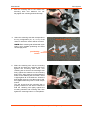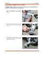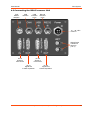
1
DCA System
Sensor System
for
Dynamic Camber Angle Measurement
USER MANUAL
VOLUME I
Sensor Hardware
User Manual
DCA System
Note: For a general description of the CeCalWin Pro Software refer
to the separate user manual Volume II.
For the specific software description for the DCA-System
Sensor refer to the separate user manual Volume III.
© 2008 CORRSYS-DATRON Sensorsysteme GmbH, Germany
DCA_m-628-p1-e-rev001
10/08
2
User Manual
DCA System
VOLUME I - Sensor Hardware
Table of Contents
General Information . . . . . . . . . . . . . . . . . . . . . . . . . . . . . . . . . . . . . . . . . . . .4
Safety Instructions . . . . . . . . . . . . . . . . . . . . . . . . . . . . . . . . . . . . . . . . . . . . .5
1.
Overview . . . . . . . . . . . . . . . . . . . . . . . . . . . . . . . . . . . . . . . . . . . . . . . . . .6
2.
Extent of Delivery . . . . . . . . . . . . . . . . . . . . . . . . . . . . . . . . . . . . . . . . . .8
3.
Technical Data . . . . . . . . . . . . . . . . . . . . . . . . . . . . . . . . . . . . . . . . . . . .10
3.1 Specifications . . . . . . . . . . . . . . . . . . . . . . . . . . . . . . . . . . . . . . . . . . .10
3.2 Pin Assignments . . . . . . . . . . . . . . . . . . . . . . . . . . . . . . . . . . . . . . . . .11
.....
4. Set-up and Connection . . . . . . . . . . . . . . . . . . . . . . . . . . . . . . . . . . . .13
4.1 Standard Mounting . . . . . . . . . . . . . . . . . . . . . . . . . . . . . . . . . . . . . . .13
4.2 Mounting a CORREVIT® SF-II P Sensor . . . . . . . . . . . . . . . . . . . . . . .18
4.3 Connecting the DCA Processor Unit . . . . . . . . . . . . . . . . . . . . . . . . . .19
5.
Troubleshooting . . . . . . . . . . . . . . . . . . . . . . . . . . . . . . . . . . . . . . . . . . .20
CORREVIT® is a registered trademark of CORRSYS-DATRON Sensorsysteme GmbH, Wetzlar Germany. In a continuous
effort to improve our products CORRSYS-DATRON reserves the right to change specifications without prior notice.
© 2008 CORRSYS-DATRON Sensorsysteme GmbH, Germany
DCA_m-628-p1-e-rev001
10/08
3
User Manual
DCA System
General Information
Legal Notice
Information furnished is believed to be accurate and reliable. However, CORRSYS-DATRON assumes
no responsibility for the consequences of use of such information nor for any infringement of patents
or other rights of third parties which may result from its use. No license is granted by implication or
otherwise under any patent or patent rights of CORRSYS-DATRON. Specifications mentioned in this
publication are subject to change without notice and do not represent a commitment on the part of
CORRSYS-DATRON. This publication supersedes and replaces all information previously supplied.
All brand names are trademarks of their respective holders.
Copyright Notice
©Copyright 2008, CORRSYS-DATRON
Revision
DCA_m-628-p1-e-rev001
10/08
Contact
International Headquarters:
CORRSYS-DATRON Sensorsysteme GmbH
Charlotte-Bamberg-Str. 12
35523 Wetzlar / Germany
Phone ++49 (6441) 9282-0
Hotline ++49 (6441) 9282-82
Fax
++49 (6441) 9282-17
E-mail [email protected]
URL
www.corrsys-datron.com
North American Headquarters:
CORRSYS-DATRON Sensorsystems, Inc.
40000 Grand River, Suite 503
Novi, MI 48375 / USA
Phone ++1 (248) 615-2035
Toll-free++1 (800) 832-0732
Fax
++1 (248) 615-2184
E-mail [email protected]
URL
www.corrsys-datron.com
China Headquarters:
CORRSYS-DATRON Sensorsysteme GmbH, China Office
Room 708, JinTianDi International Mansion,
No. 998 RenMin Road, Shanghai (200021), P.R.China
Tel.: ++86-21-63114144
Fax: ++86-21-63114154
E-mail: [email protected]
URL: www.corrsys-datron.com.cn
© 2008 CORRSYS-DATRON Sensorsysteme GmbH, Germany
DCA_m-628-p1-e-rev001
10/08
4
User Manual
DCA System
Safety Instructions
Please read carefully before operating the equipment.
CORRSYS-DATRON is not responsible for damage that may occur when this system is used in any way
other than that for which it is intended.
To assure safe and proper operation, all supplied equipment, components and/or accessories must be
carefully transported and stored, as well as professionally installed and operated. Careful maintenance
and usage in full accordance with operating instructions is imperative.
CORRSYS-DATRON equipment should be installed and operated only by qualified persons who are
familiar with devices of this type.
Local regulations may not permit the operation of motor vehicles on public highways while the equipment
is mounted on the exterior of the vehicle.
• Use the equipment only for intended applications. Improper application is not advised.
• Do not modify or change the equipment or its accessories in any way.
• Improper use or mounting of the equipment may affect the safety of the vehicle and/or occupants.
• The equipment must not be mounted and/or operated in any way that may compromise vehicle
and/or occupant safety.
• Equipment must be mounted firmly and securely.
• Use only original equipment, components and/or accessories included in the scope of delivery.
• Do not use defective or damaged equipment, components and/or accessories .
• Always note correct pin assignments and operating voltages when connecting equipment
to power supplies, data acquisition/evaluation systems, and/or any other applicable system or
component. Equipment may be damaged if not properly connected and/or operated.
• For additional information, please call the CORRSYS-DATRON Hotline: ++49 (6441) 9282-82
or email: [email protected].
• Caution: Laser radiation is emitted from this device!
Do not stare into beam!
Laser class 3R according to DIN EN 60825-1:2001-11
• Disconnect power from the sensor if the vehicle is stationary for extended periods.
© 2008 CORRSYS-DATRON Sensorsysteme GmbH, Germany
DCA_m-628-p1-e-rev001
10/08
5
User Manual
DCA System
1. Overview
DCA System
Sensor System
for
Dynamic Camber Angle
Measurement
Article no.:
DCA-1 System for camber angle
measurement at one wheel
15905
DCA-2 System for camber angle
measurement at two wheels
15906
DCA-System for camber angle
measurement without processor 15907
Dynamic Camber Angle Measurement
Using two CORRSYS-DATRON HF-500C or HF-750C Ride Height Sensors mounted on the vehicle
wheel, accurate dynamic measurement of wheel camber relative to ground is at last a reality.
This ingenious new system acquires dynamic wheel camber angle by comparing the relative change in
height between the two sensors, as measured from the optical plane of each sensor to the surface of the
road or track.
The system also provides the option to mount CORREVIT® SFII-P Sensor for non-contact measurement
of speed/slip angle
© 2008 CORRSYS-DATRON Sensorsysteme GmbH, Germany
DCA_m-628-p1-e-rev001
10/08
6
User Manual
DCA System
Features
• Measures camber angle relative to ground
• Mounts easily onto the vehicle wheel with collets that clamp directly to the wheel nuts.
Collets are available for most standard wheel types
• Universal application
• Online display via CeCalWin Pro Software
• Parameterization via CeCalWin Pro Software
• DCA Processor supports one or two sensor systems
• Data output via CAN, USB, and analog output
• Optional mounting of a CORREVIT® SFII-P Sensor for non-contact measurement of slip angle
• For passenger cars and SUVs
• Truck version available on request.
• Uses two CORRSYS-DATRON HF-500C or HF-750C Laser Height Sensors, proven accurate in
extreme environmental conditions, including intense sunlight, and high temperature and humidity, as
found in India and Arizona.
© 2008 CORRSYS-DATRON Sensorsysteme GmbH, Germany
DCA_m-628-p1-e-rev001
10/08
7
User Manual
DCA System
2. Extent of Delivery
Standard extent of delivery, article no. 15905
DCA-1 System for camber angle measurement at one wheel
without collets and centering stars
1. 14582 (1) Wheel mounting complete RV4 and DCA
2. 15237 (1) Mounting HF for DCA system without sensors
3. 13195 (1) Bar double hub for SL wheel mounting unit and WPT (top)
4. 11290 (1) Hexagon wrench set SW2-8
5. 15380 (2) pcs HF-500C with CAN *
6. 15232 (1) Sensor cable 5m DCA Processor - 2x HF-Sensors
7. 14892 (1) Processor for DCA system
8. 10397 (1) Power cable 5m B-coded 4pin, Banana plug
9. 13946 (1) Can cable 2m 3pin Binder 9pin, Sub-D
10. 13425 (1) RS232 cable 2m 4pin Binder -> 9pin, Sub-D
11. 13947 (1) USB cable 2m ->4pin Binder
12. 14977 (1) Distributor cable 1m HD-SUB - 5xBNC DCA
13. 11343 (1) Software, CeCalWin Pro
14. 11428 (2) Calibration according to DIN EN ISO 9001, Manufacturer Certificate "M" according to
DIN 55350 part 18 for all 1-axis sensors
Standard extent of delivery, article no. 15906
DCA-2 System for camber angle measurement at two wheels
without collets and centering stars
1. 14582 (2) Wheel mounting complete RV4 and DCA
2. 15237 (2) Mounting HF for DCA system without sensors
3. 13195 (2) Bar double hub for SL wheel mounting unit and WPT (top)
4. 11290 (1) Hexagon wrench set SW2-8
5. 15380 (4) pcs HF-500C with CAN *
6. 15232 (2) Sensor cable 5m DCA Processor - 2x HF-Sensors
7. 14892 (1) Processor for DCA system
8. 10397 (1) Power cable 5m B-coded 4pin, Banana plug
9. 13946 (1) Can cable 2m 3pin Binder 9pin, Sub-D
10. 13425 (1) RS232 cable 2m 4pin Binder -> 9pin, Sub-D
11. 13947 (1) USB cable 2m ->4pin Binder
12. 14977 (2) Distributor cable 1m HD-SUB - 5xBNC DCA
13. 11343 (1) Software, CeCalWin Pro
14. 11428 (4) Calibration according to DIN EN ISO 9001, Manufacturer Certificate "M" according to
DIN 55350 part 18 for all 1-axis sensors
* alternatively, the DCA System can be equipped with two HF-750C Sensors (art.no. 15914)
© 2008 CORRSYS-DATRON Sensorsysteme GmbH, Germany
DCA_m-628-p1-e-rev001
10/08
8
User Manual
DCA System
Standard extent of delivery, article no. 15907
DCA System for camber angle measurement at one wheel
without processor, collets and centering stars
1. 14582 (1) Wheel mounting complete RV4 and DCA
2. 15237 (1) Mounting HF for DCA system without sensors
3. 13195 (1) Bar double hub for SL wheel mounting unit and WPT (top)
4. 11290
(1) Hexagon wrench set SW2-8
5. 15380 (2) pcs HF-500C with CAN
6. 11343 (1) Software, CeCalWin Pro
7. 11428 (2) Calibration according to DIN EN ISO 9001, Manufacturer Certificate "M"
according to DIN 55350 part 18 for all 1-axis sensors
* alternatively, the DCA System can be equipped with two HF-750C Sensors (art.no. 15914)
Options / Accessories
• Wheel Incremental Transducer including mounting accessories and cables, article no. 14907
Transducer with mounting equipment for RV-4 and DCA
• CORREVIT® SF Sensor (standard extent of delivery and mounting accessories)
Article no. 14391 - SFII P and article no. 14623 = mounting accessories (bracket) SFII P Sensor for
DCA System
© 2008 CORRSYS-DATRON Sensorsysteme GmbH, Germany
DCA_m-628-p1-e-rev001
10/08
9
User Manual
DCA System
3.
Technical Data
3.1
Technical Specifications
Sensor position relative to wheel center: 62 ... 195 mm
Working distance and range:
HF-500C: 125 ... 625 mm / HF-750C: 150 ... 900 mm
Max. wheel diameter:
≤
Max. measuring range, camber angle*:
±25°
Resolution, camber angle*:
0.04°
Accuracy, camber angle*:
<0.5°
Moving mass at the wheel:
approx. 3.4 kg
Light source:
Laser, 660 nm (red), < 5 mW
Laser class:
3R (IEC 60825-1)
Approx. spot size:
1 mm x 2 mm
Collets (optional):
17, 19, and 21 mm
14, 20, 22, 23, 24, 26, 27, and 30 mm
(other sizes available upon request)
800 mm
*values based on a basis length of 162 mm
System Specifications
Power supply:
10 ... 36 V DC
Supply current:
< 0.5 A
Temperature range:
Operating:
Storage:
-10 … 50°C
-20 … 60°C
System protection of the sensors:
System protection of the processor:
IP 65
IP 55
Outputs
Output signals:
Camber Angle
Height 1, Height 2
Wheel Speed**, Wheel Position**
Calculated Distance**
Update rate:
4 ms (250 Hz)
CAN Bus:
CAN V2.0B - switchable terminating
resistor (Intel or Motorola Format)
Analog Outputs:
±10V each (16 bit resolution)
PC interface:
USB 2.0 full speed and RS232
Adjustable filter time:
unfiltered or 4 ... 512 ms
All inputs and outputs are protected against overvoltage and short circuit.
CAUTION
Laser radiation is emitted from this device.
Do not stare into beam!
Laser Class 3R according to DIN EN 60825-1:2001-11
≤ 5 mW
Laser Power
Wave Length 660 nm
© 2008 CORRSYS-DATRON Sensorsysteme GmbH, Germany
**optional, with Wheel
Pulse Transducer Art.no. 11355
DCA_m-628-p1-e-rev001
10/08
10
User Manual
3.2
DCA System
Pin Assignments
ATTENTION!
All views are of the front of the connector.
2
1
Light Barrier
3-pin Lemo, Series 1S
Pin 1: light barrier signal
Pin 2: GND
Pin 3: +12V
3
4
CAN
3-pin Binder 718 flange connector, male
Pin 1: CAN high
Pin 3: CAN low
Pin 4: CAN GND
1
3
© 2008 CORRSYS-DATRON Sensorsysteme GmbH, Germany
DCA_m-628-p1-e-rev001
10/08
11
User Manual
DCA System
ATTENTION!
All views are of the front of the connector.
2
4
1
3
2
4
1
3
2
4
1
USB
Pin
Pin
Pin
Pin
1:
2:
3:
4:
4-pin Binder 718 flange connector, female
D+
DDGND
Switch
RS-232
Pin
Pin
Pin
Pin
1: TXD
2: RXD
3: GND
4: n.c.
Power
Pin
Pin
Pin
Pin
3
4-pin Binder 718 flange connector, male
1:
2:
3:
4:
AMP-4M-V
+12 V
+12 V
GND
GND
1
5
Sensor 1 & 2 Out
15 10
11 6
Pin
Pin
Pin
Pin
Pin
Pin
Pin
Pin
1:
2:
3:
4:
5:
6:
7:
8:
15-pin HDSub, female
Camber, analog
n.c.
H1, analog (height sensor 1)
n.c.
n.c.
H2,analog (height sensor 2)
n.c.
Velocity, analog
Sensor 1 & 2 In
Pin
Pin
Pin
Pin
Pin
Pin
Pin
9: n.c.
10: AGND
11: n.c.
12: DGND
13: Velocity, digital
14: n.c.
15: n.c.
9-pin HDSub, female
Sensor 1 & 2 Inputs should not be changed by the user.
1
3
6
4
WPT 1 & 2
Pin
Pin
Pin
Pin
Pin
Pin
1:
2:
3:
4:
5:
6:
6-pin Lemo, Series 1S, female
Pulse WPT
Zero Pulse WPT
+5 V
+12 V
DGND
n.c.
© 2008 CORRSYS-DATRON Sensorsysteme GmbH, Germany
DCA_m-628-p1-e-rev001
10/08
12
User Manual
DCA System
4. Set-up and Connection
4.1 Standard Mounting
1. Select the following parts:
Mounting disk
Mounting collet clamps
Mounting collet barrels
retainer screws and washers
2. Remove hubcap or any covering over wheel
nuts and clean dirt/debris from wheel nuts. If
the collet clamps have been separated from
the barrels (as shown above), place the
clamps inside the barrels, then place the
mounting collets firmly onto the wheel nuts.
Also be sure that the retainer screws and
washers have been removed prior to
beginning Step 3.
3. Align the mounting disc.
NOTE: Each mounting slot on the disk is
marked to ensure proper alignment with
3-, 4-, and 5-lug configurations.
Mounting slot
The markings indicate that this slot
is for 3-, 4- and 5-lug configurations.
The markings indicate that this slot
is for 3- and 4-lug configurations.
© 2008 CORRSYS-DATRON Sensorsysteme GmbH, Germany
DCA_m-628-p1-e-rev001
10/08
13
User Manual
DCA System
4. Affix the mounting disk to the collets with
mounting bolts and washers. Do not
fully tighten the mounting bolts at this step!
5. Select the centering star that corresponds to
the lug configuration (3x, 4x, or 5x) of the
wheel on which the sensor will be mounted.
Centering Stars
NOTE: Each centering star is fitted with nylon
knobs, which facilitate positioning and serve
as leverage points.
positioning
knobs
3-lug
4-lug
5-lug
6. Slide the centering star onto the mounting
disk hub and press the centering star firmly
against the mounting disk. Next, turn
centering star so that its concave edges rest
firmly against the washers on the mounting
bolts. Then, apply pressure to the positioning
knobs on the centering star, as shown, until it
is tight against all of the washers. Screw the
bolts slightly using a 5 mm allen wrench and
then tighten them firmly with a 12 Nm torque
wrench.
This will ensure that the mounting disk is
properly centered on the wheel. Continue to
hold the centering star tightly against the
mounting washers and mounting disk, then
tighten the mounting bolts in a cross pattern.
© 2008 CORRSYS-DATRON Sensorsysteme GmbH, Germany
DCA_m-628-p1-e-rev001
10/08
14
User Manual
DCA System
7. Using an allen wrench, loosen the set screw at
the bottom of the torsion rod retainer clamp and
place the retainer clamp onto the mounting
hub.
NOTE: The set screw should not be tightened
until the torsion rod is properly positioned.
(See Step 10 on page 15)
torsion rod
mounting hub
retainer clamp set screw
8. To assure proper function of the suction holders,
the mounting area must be free of grease, oil,
dust and other contaminants. For this reason it
it is necessary to clean the painted surface in
the mounting area before attaching the suction
holders. Do not use cleaning products that
leave residue of any kind on the surface. Place
the suction holders firmly against the vehicle
fender and latch the suction holder lock handles
(latched position is approximately parallel to
vehicle fender surface).
When producing the vacuum, you will
feel a distinct resistance.
9. Check the safety line to be sure it is secured to
the torsion rod. Secure the safety line at a
suitable location on the vehicle, e.g. an
additional suction holder (optional) as shown
at right.
A safety line should always
be used to avoid damage or
injury in the event that a
suction holder separates from
the vehicle body during the
test drive.
© 2008 CORRSYS-DATRON Sensorsysteme GmbH, Germany
DCA_m-628-p1-e-rev001
10/08
15
User Manual
DCA System
10. Tighten the retainer clamp set-screw with an
allen wrench (size 5).
11. Check to be certain that the HF-xxxC Height
Sensors are securely affixed to the DCA
mounting bracket.
12. Attach the DCA mounting plate on the
mounting hub and adjust parallel to the
ground using the built-in water level.
Please pay attention that the sensors are
mounted within the specified working
distance (see page 10) during the
measurement.
The mounting bracket can be adjusted up
or down on the mounting hub to achieve
the specified sensor operating range.
© 2008 CORRSYS-DATRON Sensorsysteme GmbH, Germany
DCA_m-628-p1-e-rev001
10/08
16
User Manual
DCA System
13. Tighten the mounting plate set screw with an
allen wrench (size 5)
14. Connect the signal cables to the sensors.
15. A properly mounted DCA System with two
HF-xxxC Sensors is shown at right.
For measurement of tire slip angle,
the DCA System can be fitted with an
optional CORREVIT® SFII-P Sensor.
(See section 4.2 Mounting a
CORREVIT® SF-II P Sensor page
19).
© 2008 CORRSYS-DATRON Sensorsysteme GmbH, Germany
DCA_m-628-p1-e-rev001
10/08
17
User Manual
DCA System
4.2 Mounting a CORREVIT® SF-II P Sensor
CORREVIT® SF-Series Sensors can be used in conjunction with the DCA System for
acquisition of speed, distance and angle data.
1. Secure the SFII-P Sensor to the mounting
plate for SF Sensors on DCA mounting
bracket.
2. Tighten the mounting screws with an allen
wrench and connect the signal cable to the
sensor.
3. The illustration shows the mounting of a DCA
System with two HF-xxxC Sensors and an
additional SFII-P Sensor.
© 2008 CORRSYS-DATRON Sensorsysteme GmbH, Germany
DCA_m-628-p1-e-rev001
10/08
18
User Manual
DCA System
4.3 Connecting the DCA Processor Unit
Light
Barrier
Interface
CAN
Interface
USB
Interface
to PC
RS-232
Interface
to PC
10 ... 36 V DC
Power In
Wheel Pulse
Transducer
Signal In
(1 & 2)
HF #1
Signal In
from sensor
HF #2
Signal In
from sensor
HF #1
Signal Out
to data acquisition
HF #2
Signal Out
to data acquisition
© 2008 CORRSYS-DATRON Sensorsysteme GmbH, Germany
DCA_m-628-p1-e-rev001
10/08
19
User Manual
DCA System
5. Troubleshooting
When troubleshooting the DCA Sensor System
begin by checking the following:
Cables and power supply
• Check all connections to determine that each is complete and that the system is connected to
a power supply that provides voltage output within the specified range.
• Check to determine that the correct cables have been used for all connections.
• The following problems can be caused by incorrect or incomplete cable connections and/or
connection to incorrect power supply voltage:
- Output signals are not available to data acquisition and/or connected PC.
Operating range
If the sensor is mounted out of the recommended height range (standoff distance), no measurement
signals will be output. Check and correct mounting as necessary.
Sensor lens
The sensor lens (located on the underside of the sensor housing) may occasionally become dirty,
preventing proper operation. Check and clean the sensor lens regularly.
Software
If the output signal appear to be incorrect, the sensor may have been set-up incorrectly via CeCalWin
Pro Software. Check all relevant settings in CeCalWin Pro.
Environmental conditions
The sensor may occasionally interpret heavy spray from snow or water as part of the road or track surface, producing unexplained spikes in the output signals and/or other anomalous measurement artifacts. Sensors should be mounted away from the heaviest spray areas, especially directly behind the
rear wheels.
If none of the above recommendations provides a solution, you may wish
to contact CORRSYS-DATRON. Before doing so, please be ready to supply
the following:
• A *.ccw file saved from CeCalWin Pro Software to serve as an example of the problem or fault
condition.
• The serial numbers of all relevant components.
Note: With the DCA System you have purchased a premium, high-precison product. To
assure continued optimum performance, we recommend that you send it to CORRSYSDATRON once per year for inspection, maintenance, and calibration."
© 2008 CORRSYS-DATRON Sensorsysteme GmbH, Germany
DCA_m-628-p1-e-rev001
10/08
20