1
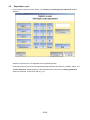
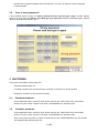
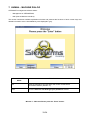
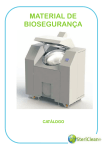
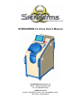
STERIGERMS 12 Litres User’s Manual
STERIGERMS International LLP
Unit 3 – 8th floor Ellerman LLP
12 – 20 Camomile street
LONDON EC3A 7PT
Phone: +33 (0)4.90.11.37.35 - Fax: +33 (0)4.90.11.37.30
VAT number : GB 8722853 06
TABLE OF CONTENTS
1.
OVERVIEW .........................................................................................................................................7
1.1.
Introduction (Figure 1) ......................................................................................................................7
1.2. Characteristics...................................................................................................................................8
1.2.1.
Physical characteristics ..................................................................................................................8
1.2.2.
Electrical characteristics.................................................................................................................8
2.
OPERATION .......................................................................................................................................9
2.1.
Connection.........................................................................................................................................9
2.2. Power-up ............................................................................................................................................9
2.2.1.
Power-up after shutdown ...............................................................................................................9
2.2.2.
Standard power-up.......................................................................................................................10
2.3.
Exploitation cycle ............................................................................................................................12
2.4.
Case of wrong password................................................................................................................21
3.
SHUTDOWN .....................................................................................................................................21
3.1.
Standard shutdown.........................................................................................................................21
3.2.
Complete shutdown ........................................................................................................................21
3.3.
Emergency shutdown .....................................................................................................................22
4.
ALARMS ...........................................................................................................................................23
5.
MAINTENANCE ................................................................................................................................25
5.1.
Table of periodic operations ..........................................................................................................25
5.2.
Cleaning of the treatment compartment .......................................................................................25
5.3.
Control of oil level ...........................................................................................................................26
5.4.
Control of cooling liquid level........................................................................................................27
5.5.
Exchange of the cover gasket........................................................................................................28
5.6.
Exchange of the particle filter ........................................................................................................28
6.
WARNING AND SAFETY SIGNS.....................................................................................................31
7.
HUMAN – MACHINE DIALOG .........................................................................................................33
8.
WARRANTY......................................................................................................................................53
3/54
4/54
LIST OF HUMAN – MACHINE INTERFACE SCREENS
TABLE OF CONTENTS .......................................................................................................................... 3
Window 1 - Welcome Please press the “Enter” button ................................................................... 33
Window 2 - Select a user And type your password ......................................................................... 34
Window 3 – Correct password ........................................................................................................... 35
Window 4 – Wrong password Please wait and type it again........................................................... 36
Window 5 - Warning (first window).................................................................................................... 37
Window 6 – Warning (second window) ............................................................................................. 38
Window 7 - Warning (third window)................................................................................................... 39
Window 8 – Select an operation......................................................................................................... 40
Window 9 - Descent of the piston ...................................................................................................... 41
Window 10 - Ejection of the compressed waste product ................................................................ 42
Window 11 - Closing Do you really want to shut down the device ................................................ 43
Window 12 – Press Start to Launch the cycle .................................................................................. 44
Window 13 - Press Confirm to launch the cycle .............................................................................. 45
Window 14 – Start compression ........................................................................................................ 46
Window 15 - Heating............................................................................................................................ 47
Window 16 – Start threshold .............................................................................................................. 48
Window 17 - Cooling ........................................................................................................................... 49
Window 18 – End of cycle................................................................................................................... 50
Window 19 – Cleaning of the machine .............................................................................................. 51
Window 20 - Machine error Only administrator can enter............................................................... 52
5/54
1
14
2
13
3
12
4
11
8
7
5
6
9
10
Figure 1 - STERIGERMS
6/54
1. OVERVIEW
1.1.
Introduction (Figure 1)
Thank you for choosing STERIGERMS for the decontamination of your IMW (Infectious Medical Waste).
STERIGERMS ensures treatment of Infectious Medical Waste, such as dressing, yellow containers used for
disposal of needles and of stinging and cutting objects, syringes, diapers, probes, blood bags, catheters,
bandages, gloves …
Combining volume reduction and decontamination by heating, STERIGERMS allows turning potentially
infectious waste into a flat-shaped compressed waste product disposable as normal household waste.
STERIGERMS is easy to use thanks to its touch screen and easy to operate, as it only requires a 16-Ampere
power supply. STERIGERMS can be operated close to the location of origin of the waste, thus limiting the
risks of contamination implied by the transport and handling of yellow bags.
STERIGERMS is composed of the following elements:
-
A locking cover (10) allowing access to the waste treatment compartment
-
A control console (4) composed of:
• a touch screen allowing human-machine dialog
• a red indicator light (6): when lit, signals a major incident
• a yellow indicator light (7): when lit, signals a minor incident without any impacts on the on-going
cycle
• a green indicator light (8): when lit, indicates correct operation
• a pushbutton (5) to power up the control console
• an emergency knock-off switch (9) to switch off mains power supply, equipped with a removable
key to unlock the cover
-
At the rear, a connection panel with the following connections:
• a nameplate (3)
• a main power-up switch (11) with light indication
• a socket (12) to connect an external power supply
• four connection elements not used for standard operation:
-
a USB connector (13)
-
a socket (14) to connect a keyboard
-
a socket (1) to connect a mouse
-
a socket (2) for an Ethernet link.
7/54
1.2.
Characteristics
1.2.1. Physical characteristics
LENGTH
(mm)
DEPTH
(mm)
HEIGHT
(mm)
WEIGHT
(kg)
460
1 050
1 120
140
1.2.2. Electrical characteristics
-
Power supply tension
:
230V
-
Frequency
:
50/60Hz
8/54
2. OPERATION
Caution:
Any identified malfunction of STERIGERMS is displayed on the banner of each window and
must be reported to the administrator.
2.1.
Connection
Caution:
Before connecting a device, always check that the power supply is of type “16A - 230V” with
earth connection (alternative current, 16 Amperes).
Connect the power cable to the socket (1, Figure 2) of STERIGERMS and to the external power supply.
2.2.
Power-up
Caution:
When powering up the equipment for the first time, contact the administrator to unlock
STERIGERMS.
There are two ways of powering up STERIGERMS:
-
Power-up after shutdown
-
Standard power-up.
2.2.1. Power-up after shutdown
-
You must perform this type of power-up after a complete shutdown of the device due to a technical
issue or a transfer of the device to another location.
Figure 2 – Rear side of STERIGERMS
-
Check that STERIGERMS is connected to the power supply network (§2.1).
-
Ensure that the emergency knock-off switch (9, Figure 1) located at the right-hand side of the
STERIGERMS control console is directed outwards; if not, bring it back to its original position using
the key and then retrieve the key.
9/54
-
Set the main power-up switch (2, Figure 2) located at the rear of STERIGERMS to the “ON” position
and check that the integrated light indicator comes on.
-
Push the control console pushbutton (4, Figure 3).
2.2.2. Standard power-up
-
Ensure that the emergency knock-off switch (9, Figure 1) located at the right-hand side of the
STERIGERMS control console is directed outwards ; if not, put it back into its original position using
the key and then retrieve the key.
-
Check that the main power-up switch (2, Figure 2), located at the rear of STERIGERMS is in the “ON”
position and that the integrated indicator light is on.
-
Push the control console pushbutton (4, Figure 3).
1
2
3
4
Figure 3 – Control console
The control console red (3, Figure 3) and yellow (2, Figure 3) indicator lights come on for about thirty
seconds (time required for initialization of Windows and Sterisoft software) and go out. Then, the
green indicator light (1, Figure 3) comes on and the Welcome page appears.
10/54
Caution:
In case of problem (if the red or yellow indicator light(s) stay(s) on), stop the power-up
procedure and contact the administrator. If the yellow indicator light comes on during a cycle, the cycle can
be completed anyway.
11/54
2.3.
Exploitation cycle
-
On the screen, select the “Enter” button. The ‘Select a user And type your password’ window
appears:
-
Select the required user. This highlights the corresponding button.
-
Using the keyboard, type in the corresponding 4-digit password and press the “Validate” button. The
‘Correct password’ window appears. If the typed password is incorrect, the ‘Wrong password’
window is displayed. In that case, refer to § 2.4.
12/54
-
On the screen, select the “Enter” button. The first ‘Warning’ window appears.
-
On the screen, select the “Validate” button. The ‘Select an operation’ window appears.
13/54
-
On the screen, select the “Descent” button to move down the piston. The following window appears:
-
Insert the waste bag into the Steribag bag for treatment,
-
Insert the Steribag bag into the STERIGERMS at the bottom of the waste treatment compartment so
that it does not overflow the edges of the container.
14/54
1) Fold the lower part of the steribag
2) Fold the top part of the steribag
3) Fold down the two tips thus formed along the barrel
Figure 4 – Waste bag closing procedure
-
Close the cover of STERIGERMS.
-
On the screen, select the “Lock” button (locking lasts about 5 seconds).
-
On the screen, select the “Cycle” button, the second ‘Warning’ window appears.
-
On the screen, select the “Validate” button, the third ‘Warning’ window appears.
15/54
-
On the screen, select the “Validate” button to access the ‘Press Start to launch the cycle’ window.
-
On the screen, select the “Start” button to access the ‘Press Confirm to launch the cycle’ window.
16/54
-
On the screen, select the “Confirm” button to launch the cycle.
During the cycle, the following windows automatically appear to visualize the various stages of the
ongoing cycle (compression, heating, treatment, cooling, end of cycle).
17/54
18/54
When the cycle has completed, the message “Waste has been processed / Waste has not been
processed” is displayed in the lower part of the screen.
-
On the screen, select the “Open device” button to return to the ‘Select an operation’ window.
19/54
-
On the screen, select the “OK” button. The “Select an operation” window appears
-
On the screen, select the “Unlock” button.
-
Open the cover of STERIGERMS.
-
On the screen, select the “Eject” button to monitor the ejection of the piston.
20/54
-
2.4.
Retrieve the compressed waste product and discard it. You can now dispose of it as of standard
household waste.
Case of wrong password
If the password typed is wrong, the ‘Wrong password Please wait and type it again’ window appears
during 4 seconds, then the ‘Select a user And type your password’ window is displayed again. Perform
again the procedure described in § 2.3.
3. SHUTDOWN
Three types of shutdown can be performed:
-
Standard shutdown after use
-
Complete shutdown due to technical issue or transfer of the device to another location
-
Emergency shutdown in case of serious incident
3.1.
-
3.2.
Standard shutdown
On the displayed screen, select the “Quit” button and then the “YES” button of the confirmation
window. Only the control console is shut down, STERIGERMS is in stand-by mode.
Complete shutdown
-
On the displayed screen, select the “Quit” button and then the “YES” button of the confirmation
window. Only the control console is shut down, STERIGERMS is in stand-by mode.
-
Set the main power-up switch (2, Figure 2) located at the rear of STERIGERMS to the “Off” position.
The integrated light indicator goes out.
21/54
3.3.
-
Emergency shutdown
Push the emergency knock-off switch (9, Figure 1) located at the right-hand side of the STERIGERMS
control console. This action will switch off main power supply.
22/54
4. ALARMS
DISPLAYED ALARMS
EXPLAINATION
ACTIONS
Liquid detected
Presence of liquid under the cover
None
Waste product too thick
Thickness of compressed waste
product exceeds 12 cm
None
Power outage
Once power supply has been
restored, cycle is restarted from the
point of interruption caused by
power outage
None
Low tension
Tension of external power supply is
less than 215 V
Contact the administrator
Pressure too high
Cylinder pressure too high
Contact the administrator
Lack of cooling liquid
Cooling liquid level too low
Fill up with cooling liquid
Upper banner of the
screen is red (see
following window)
Internal malfunction
Contact the administrator
23/54
24/54
5. MAINTENANCE
5.1.
Table of periodic operations
OPÉRATIONS
FREQUENCY
PROCÉDURES
Cleaning of the treatment
compartment
After each cycle
§ 5.2
Control of oil level
Twice a month
§ 5.3
Control of cooling liquid level
In case of alarm
§ 5.4
Exchange of the cover gasket
Twice a year or after production of
300 compressed waste products
§ 5.5
Exchange of the particle filter
Twice a year or after production of
300 compressed waste products
§ 5.6
5.2.
Cleaning of the treatment compartment
-
Do not use any abrasive, scrubbing or metallic sponge or sharp or cutting object for cleaning
-
Clean the treatment compartment, the cover and the cover gasket surface using kitchen towel
-
You can optionally use the provided scraper (Figure 5) to remove plastic bag residues on parts made
of stainless steel (cover and piston)
Figure 5 - Scraper
-
Lubricate the gasket with a standard oil that supports temperatures exceeding 145 °C
-
Remove residual stains (blood, gelose…) with a sponge and regular liquid soap.
25/54
5.3.
Control of oil level
During this operation, the piston must be kept in low position:
-
Unscrew the two ¼’’ fastening screws (Pozidriv no 1 screwdriver) on the left flank. Tilt the flank down
on your side and pull it upwards to remove it.
-
Check that oil level is within the limits indicated on the oil tank.
• If oil level is correct, engage the right flank on the locating pins located at the bottom of the tank,
press the flank against the chassis and tighten it using the two ¼’’ fastening screws (Pozidriv no 1
screwdriver).
• Il oil level is too low, top up with oil (32 hydraulic synthetic oil):
-
Unscrew the two ¼’’ fastening screws (Pozidriv no 1 screwdriver) on the right flank. Tilt the flank
down on your side and pull it upwards to remove it.
-
Remove the oil tank cap (1).
-
Insert a flexible funnel of the same type as the one shown on Figure 6.
Figure 6 – Flexible funnel
-
Top up with oil (with a level slightly below the maximum indicated on the tank).
-
Remove the flexible funnel.
-
Replace the oil tank cap (1).
1
Figure 7 – Control of oil level
26/54
-
Engage the left flank on the locating pins located at the bottom of the tank, press the flank against the
chassis and tighten it using the two ¼’’ fastening screws (Pozidriv no 1 screwdriver).
-
Engage the right flank on the locating pins located at the bottom of the tank, press the flank against
the chassis and tighten it using the two ¼’’ fastening screws (Pozidriv no 1 screwdriver).
5.4.
Control of cooling liquid level
When the cooling liquid level is too low, an alarm is automatically triggered. If so, you must top up the cooling
liquid reservoir with cooling liquid (STERIGERMS must be powered up during this operation):
-
Unscrew the two ¼’’ fastening screws (Pozidriv no 1 screwdriver) on the left flank. Tilt the flank down
on your side and pull it upwards to remove it.
-
Remove the cap (1) of the cooling liquid reservoir.
-
Add demineralised water until the alarm stops.
-
Replace the cap (1) of the cooling liquid reservoir.
1
Figure 8 – Control of cooling liquid level
-
Engage the left flank on the locating pins located at the bottom of the tank, press the flank against the
chassis and tighten it using the two ¼’’ fastening screws (Pozidriv no 1 screwdriver).
27/54
5.5.
Exchange of the cover gasket
-
Open the cover of STERIGERMS.
-
Remove the gasket (1, Figure 9) using a screwdriver and discard it.
Figure 9 - Exchange of the cover gasket
-
Put a new gasket and grease it with high temperature (180 °C) grease (of type DARINA R2).
-
Close the cover.
5.6.
-
Exchange of the particle filter
Unscrew the 5 fastening screws (1, Figure 10) (3mm hexagonal key) on the plastic cover of
STERIGERMS and remove the plastic cover.
Figure 10 – Removal of the plastic cover
-
Unscrew the 2 fastening screws (2 and 7, Figure 11) (3mm hexagonal key) of the filter cap insulating
grid (1, Figure 11).
-
Open the cover of STERIGERMS and remove the filter cap insulating grid (1, Figure 11).
-
Close the cover of STERIGERMS.
-
Unscrew the 4 fastening screws (3 and 6, Figure 11) of the filter cap (5, Figure 11) (4mm hexagonal
driver).
28/54
Figure 11 – Removal of the filter plug
-
Tilt the filter cap (3, Figure 12) to gain access to the particle filter (2, Figure 12) casing.
-
Remove and discard the particle filter (2, Figure 12) using a screwdriver.
Figure 12 – Exchange of the particle filter
-
Clean soiled parts (§ 5.2).
-
Check the status of the filter cap gasket (1, Figure 12). You can optionally clean the gasket (§ 5.2) or
exchange it if necessary:
• Remove the filter cap gasket (1, Figure 12) and discard it.
• Insert a new gasket (1, Figure 12).
-
Insert a new particle filter (2, Figure 12) in its casing.
-
Put back the filter cap (5, Figure 11) into position and fasten it with its 4 fastening screws (3 and 6,
Figure 11) (4mm hexagonal driver).
-
Open the cover of STERIGERMS and insert the filter cap insulating grid (1, Figure 11).
29/54
-
Close the cover of STERIGERMS.
-
Screw the 2 fastening screws (2 and 7, Figure 11) (4mm hexagonal key) of the filter cap insulating
grid.
-
Replace the plastic cover of STERIGERMS and screw the 5 fastening screws (1, Figure 10) (3mm
hexagonal key).
30/54
6. WARNING AND SAFETY SIGNS
Prohibited
-
Do not introduce any pressurized containers such as spray bombs.
-
Do not introduce flammable products.
-
Do not introduce explosives substances.
-
Do not perform cycles when the device is empty.
-
Do not perform prior compaction.
-
Do not process compressed waste products with a thickness exceeding 10cm, or in
other words bags weighing more than 4kg.
-
Do not introduce any of the products mentioned in the 26 July 1991 circular, volatile
toxic substances (including cytostatic drugs) or waste with potential risks of "prion"
infection.
-
Do not introduce waste destined for another treatment line, such as mercury, lead,
electric cells, batteries, acids, alkaline compounds radioactive products, etc…
-
Do not dispose of living animals and/or of recognisable human anatomical parts.
-
Do not dispose of waste containing plastics for any other purpose than medical or
alimentary.
-
Do not introduce hermetic bags into the device, to guarantee correct operation.
Compulsory
-
Use the specific Steribag bags developed and validated by the company
STERIGERMS and agreed by the “Conseil Supérieur de l’Hygiène Publique de
France”, indispensable for proper waste processing. Waste products processed
without this bag will not be considered as sanitized.
-
Condition stinging/cutting objects, glass, ceramics and minerals (Sand, gravels) in
boxes to that effect. Boxes and other types of waste must be introduced directly into
the Steribag bags. Prosthesis and teeth are considered to be cutting/stinging objects.
For the compressed waste product to conform to regulations regarding household waste
disposal, liquid products cannot exceed 30% of the total weight of a load of processed
waste, so as to keep the waste encapsulated in a sufficiently rigid package.
If waste disinfection is validated by the device (the message “waste processed
successfully” appears on the screen), you can dispose of the compressed waste product
via the same treatment line as any household waste. If not, the compressed waste product
is not disinfected and must imperatively by disposed of via a specialized treatment line for
IMW (Infectious Medical Waste) or otherwise reprocessed.
If there are remaining liquids in the bin after validation by the device of waste disinfection,
you can empty the bin from its contents and dispose of it as of any standard liquid
household waste product.
31/54
It is forbidden to introduce flammable products.
It is forbidden to introduce pressurized products such as spray bombs (full or empty).
Use of the Steribag bag is compulsory.
Stinging and cutting objects and glass must be conditioned in a box conform to the norms
and intended for this purpose (yellow boxes) before their disposal into the Steribag bag.
32/54
7. HUMAN – MACHINE DIALOG
STERISOFT management software allows:
-
Management of STERIGERMS,
-
HMI (Human Machine Interface).
This section introduces available exploitation windows and presents the functions of touch screen keys and
related information zones. Unavailable keys are displayed in grey.
TOUCH SCREEN
KEYS
FUNCTIONS
Quit
Close the application and shut down the control console with a
confirmation window (Window 11)
Enter
Go to the ‘Select a user And type your password’ window
Window 1 - Welcome Please press the “Enter” button
33/54
TOUCH SCREEN
KEYS
FUNCTIONS
User 1/2/3/4
Select the required user
Validate
Acknowledge and validate the typed password and open the ‘Correct
passwiord’ or the ‘Wrong password’ window. This key is only available
when the 4 digits of the password have been typed.
Keyboard
Set of keys allowing to type the password
Exit
Go back to the previous window
Quit
Unavailable
Enter
Unavailable
Del.
Delete the last digit
Reset
Delete all the typed digits
Window 2 - Select a user And type your password
34/54
TOUCH SCREEN
KEYS
FUNCTIONS
User 1/2/3/4
Unavailable
Administrator
Unavailable
Validate
Unavailable
Keyboard
Unavailable
Exit
Unavailable
Quit
Close the application and shut down the control console with a
confirmation window (Window 11)
Enter
Go to the next window
Window 3 – Correct password
35/54
Display of this screen is temporary and all the keys are unavailable.
After about 4 seconds, the ‘Select a user And type your password’ window appears again, allowing to
type the password again.
Window 4 – Wrong password Please wait and type it again
36/54
TOUCH SCREEN
KEYS
FUNCTIONS
Validate
Go to the next window
Quit
Unavailable
Exit
Unavailable
Window 5 - Warning (first window)
37/54
TOUCH SCREEN
KEYS
FUNCTIONS
Back
Go back to the ‘Select an operation’ window
Validate
Go to the next window
Quit
Unavailable
Exit
Unavailable
Window 6 – Warning (second window)
38/54
TOUCH SCREEN
KEYS
FUNCTIONS
Back
Go back to the second warning window
Validate
Go to the cycle window
Quit
Unavailable
Exit
Unavailable
Window 7 - Warning (third window)
39/54
TOUCH SCREEN
KEYS
FUNCTIONS
Descent
Control to move the piston downwards
Ejection
Control to move the piston upwards
Lock
Control to lock the cover
Unlock
Control to unlock the cover
Cycle
Go to the cycle window
Quit
Close the application and shut down the control console with a
confirmation window (Window 11)
Exit
Go back to the welcome window
Window 8 – Select an operation
40/54
TOUCH SCREEN
KEYS
FUNCTIONS
Stop descent
Control to stop the descent of the piston
Ejection
Unavailable
Lock
Unavailable
Unlock
Unavailable
Cycle
Unavailable
Quit
Unavailable
Exit
Unavailable
Window 9 - Descent of the piston
41/54
TOUCH SCREEN
KEYS
FUNCTIONS
Descent
Unavailable
Stop ejection
Control to stop ejection of the compressed waste product
Lock
Unavailable
Unlock
Unavailable
Cycle
Unavailable
Quit
Unavailable
Exit
Unavailable
Window 10 - Ejection of the compressed waste product
42/54
TOUCH SCREEN
KEYS
FUNCTIONS
Yes
Close the application and shut down the control console
No
Go back to the previous window
Quit
Unavailable
Enter
Unavailable
Window 11 - Closing Do you really want to shut down the device
43/54
TOUCH SCREEN
KEYS
FUNCTIONS
Start
Launch the cycle
Back
Go back to the warning window
INFORMATION
ZONES
SIGNIFICATION
Information
Unavailable
Cycle
Unavailable
Compression
Unavailable
Heating
Unavailable
Threshold
Unavailable
Cooling
Unavailable
End of cycle
Unavailable
Current
Electrical consumption of STERIGERMS in sleeping mode
Tension
Tension value of the electrical network
Thick. waste product
Position of the piston (340mm corresponds to low position)
Window 12 – Press Start to Launch the cycle
44/54
TOUCH SCREEN
KEYS
FUNCTIONS
Confirm
Confirm launch of the cycle
Back
Go back to the previous window
INFORMATION
ZONES
SIGNIFICATION
Information
Unavailable
Cycle
Unavailable
Compression
Unavailable
Heating
Unavailable
Threshold
Unavailable
Cooling
Unavailable
End of cycle
Unavailable
Current
Electrical consumption of STERIGERMS in sleeping mode
Tension
Tension value of the electrical network
Thick. waste product
Position of the piston (340mm corresponds to low position)
Window 13 - Press Confirm to launch the cycle
45/54
INFORMATION
ZONES
SIGNIFICATION
Information
Display of detected malfunction (§4)
Cycle
Cycle number
Compression
Display of compression phase
Heating
Unavailable
Threshold
Unavailable
Cooling
Unavailable
End of cycle
Unavailable
Current
Electrical consumption of STERIGERMS in sleeping mode
Tension
Tension value of the electrical network
Thick. waste product
Position of the piston (340mm corresponds to low position)
Window 14 – Start compression
46/54
INFORMATION
ZONES
SIGNIFICATION
Information
Display of detected malfunction (§4)
Cycle
Cycle number
Compression
Display of completed compression phase
Heating
Display of heating phase parameters
Threshold
Unavailable
Cooling
Unavailable
End of cycle
Unavailable
Current
Electrical consumption of STERIGERMS during heating phase
Tension
Tension value of the electrical network
Thick. waste product
Position of the piston (340mm corresponds to low position)
Window 15 - Heating
47/54
INFORMATION
ZONES
SIGNIFICATION
Information
Display of detected malfunction (§4)
Cycle
Cycle number
Compression
Display of completed compression phase
Heating
Display of heating phase parameters
Threshold
Display of processing phase parameters
Cooling
Unavailable
End of cycle
Unavailable
Current
Electrical consumption of STERIGERMS during processing phase
Tension
Tension value of the electrical network
Thick. waste product
Thickness of the compressed waste product
Window 16 – Start threshold
48/54
INFORMATION
ZONES
SIGNIFICATION
Information
Display of detected malfunction (§4)
Cycle
Cycle number
Compression
Display of completed compression phase
Heating
Display of heating phase parameters
Threshold
Display of processing phase parameters
Cooling
Display of cooling phase parameters
End of cycle
Unavailable
Courant
Electrical consumption of STERIGERMS during cooling phase
Tension
Tension value of the electrical network
Thick. waste product
Thickness of the compressed waste product
Window 17 - Cooling
49/54
TOUCH SCREEN KEYS
Open the device
FUNCTIONS
Go back to the ‘Select an operation’ window
INFORMATION ZONES
SIGNIFICATION
Information
Display of detected malfunction (§4)
Cycle
Cycle number
Compression
Display of completed compression phase
Heating
Display of heating phase parameters
Threshold
Display of processing phase parameters
Cooling
Display of cooling phase parameters
End of cycle
Display of end of cycle phase parameters
Waste has been processed
Display of processing result after cycle completion
Current
Electrical consumption of STERIGERMS after cycle completion
Tension
Tension value of the electrical network
Thick. waste product
Thickness of the compressed waste product
Window 18 – End of cycle
50/54
TOUCH SCREEN KEYS
OK
FUNCTIONS
Go back to the ‘Select an operation’ window
Window 19 – Cleaning of the machine
51/54
Window 20 - Machine error Only administrator can enter
52/54
8. WARRANTY
The STERIGERMS contractual warranty shall not apply in case of non-observance of any of the instructions
as set out in the User’s Manual.
The device complies with the following European directives:
89/392/CEE dated 06/14/89 modified
73/23/CEE dated 02/19/73 modified
89/336/CEE dated 05/03/89 modified
53/54
54/54