1
GE Vingmed Ultrasound
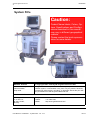
System FiVe
User Manual for
Software Version 1.9.x
GEVU P.No.: FA092423
GEVU Revision:L
GEMS Cat.No.: H44701VA
Verify the System
Software version as
shown on page 35
CAUTION:
Federal law restricts this device to sale by or on the order of a physician.
GE Vingmed Ultrasound
Intro-2
User Manual - FA092423 L - System FiVe - sw. 1.9.x
GE Vingmed Ultrasound
Introduction
System FiVe
Caution:
Product Name labels, Colors, Options, Specifications and Configurations described in this manual
may vary in different geographical
markets.
Please contact the local representative for more details.
MANUAL STATUS
© Copyright 1996 – 2000 by GE Vingmed Ultrasound AIS.
Printed in Norway.
eleventh edition,
Sept-2000.
All rights reserved. No part of this Manual may be reproduced, stored in a
retrieval system, or transmitted, in any form or by any means, electronic,
mechanical, photocopying, recording, or otherwise, without the prior written permission from GE Vingmed Ultrasound AIS.
COMPANY DATA:
GE Vingmed Ultrasound A/S,
P. O. Box 141,
N-3191 Horten,
Norway.
Telephone:
Telefax:
WWW:
User Manual - FA092423 L - System FiVe - sw. 1.9.x
+47 3302 1100
+47 3302 1350
http://www.geultrasound.com/
Intro-3
Introduction
GE Vingmed Ultrasound
INTRODUCTION
GE Vingmed Ultrasound
GE Vingmed Ultrasound is ISO 9001 (1994) and EN 46001 certified. Copies of the certificates are available on request.
System FiVe
System FiVe is an Ultrasound Diagnostic System for applications such as Adult, Pediatric
and Neonatal Cardiac, Peripheral Vascular, Abdominal and Ob-Gyn. (See: Indications for
use, page 207.)
Probes
The System FiVe allows the use of various probes. Refer to a Probe / Application overview
list on page 208.
User Interface
The System FiVe has an intuitive yet flexible user interface philosophy. All the tools are readily available when needed.
Operating Modes
The system controls operate the following modes: Color Flow, 2-D Image, Color M-Mode, MMode, HPRF Doppler, LPRF Doppler and CW Doppler, or a combination of these, positioned
on the operating panel.
Intro-4
User Manual - FA092423 L - System FiVe - sw. 1.9.x
GE Vingmed Ultrasound
Introduction
System FiVe’s User Manual
Using this manual:
• The TOC of this manual contains, in the order from front to rear, the heading on each
page of the manual from Chapter A and
backwards.
• The manual has continuous numbering from Chapter A and backwards.
• The manual has an index at the very rear which contains minimum 1, maximum 3 entries from each pageof this manual.
IMPORTANT.
This manual is periodically revised. Changes, typographic errors and technical inaccuracies, which may be included, will be corrected in future revisions.
FEEDBACK.
Any views and comments concerning the product (including its manuals) should be forwarded to the local GE Vingmed Ultrasound product representative or GE Vingmed Ultrasound Head office in Horten, Norway. The official address, is found on page 3 of this
chapter.
User Manual - FA092423 L - System FiVe - sw. 1.9.x
Intro-5
INTRODUCTION
GE Vingmed Ultrasound
Table of Contents
Chapter A1
System Preparations
. . . . . . . . . . . . . . . . . . . . . . . . . . . . . . . . . . .1
Turn ON the system . . . . . . . . . . . . . . . . . . . . . . . . . . . . . . . . . . . . . . . . . . . . . . . . .2
Connect Power cable and locate Power switches . . . . . . . . . . . . . . . . . . . . . . . . 2
The Power-Up process . . . . . . . . . . . . . . . . . . . . . . . . . . . . . . . . . . . . . . . . . . . . . 3
System Probes . . . . . . . . . . . . . . . . . . . . . . . . . . . . . . . . . . . . . . . . . . . . . . . . . . . . .4
Probe connections
. . . . . . . . . . . . . . . . . . . . . . . . . . . . . . . . . . .4
Change APAT Probes at Cable end . . . . . . . . . . . . . . . . . . . . . . . . . . . . . . . . . 5
System-Connect Probe cabling . . . . . . . . . . . . . . . . . . . . . . . . . . . . . . . . . . . . . 6
Active Probe and Application Selection . . . . . . . . . . . . . . . . . . . . . . . . . . . . . . . 7
Patient I/O & traces setup . . . . . . . . . . . . . . . . . . . . . . . . . . . . . . . . . . . . . . . . . . . .8
Connect ECG harness . . . . . . . . . . . . . . . . . . . . . . . . . . . . . . . . . . . . . . . . . . . . . 8
Screen changes after ECG connection . . . . . . . . . . . . . . . . . . . . . . . . . . . . . . . . . 9
ECG trace control . . . . . . . . . . . . . . . . . . . . . . . . . . . . . . . . . . . . . . . . . . . . . . . . . 10
ECG GAIN Adjustment . . . . . . . . . . . . . . . . . . . . . . . . . . . . . . . . . . . . . . . . . . . . . 11
Set ECG trigger one . . . . . . . . . . . . . . . . . . . . . . . . . . . . . . . . . . . . . . . . . . . . . . . 12
Set ECG trigger two . . . . . . . . . . . . . . . . . . . . . . . . . . . . . . . . . . . . . . . . . . . . . . . 13
Timer Delay . . . . . . . . . . . . . . . . . . . . . . . . . . . . . . . . . . . . . . . . . . . . . . . . . . . . . . 14
Timer Trigging . . . . . . . . . . . . . . . . . . . . . . . . . . . . . . . . . . . . . . . . . . . . . . . . . . . . 15
Connect other trace sources . . . . . . . . . . . . . . . . . . . . . . . . . . . . . . . . . . . . . . . . . 16
Trace area size . . . . . . . . . . . . . . . . . . . . . . . . . . . . . . . . . . . . . . . . . . . . . . . . . . . 17
Footswitch . . . . . . . . . . . . . . . . . . . . . . . . . . . . . . . . . . . . . . . . . . . . . . . . . . . . . . . .18
Mount the System Footswitch . . . . . . . . . . . . . . . . . . . . . . . . . . . . . . . . . . . . . . . . 18
Finding the Footswitch Mapping option . . . . . . . . . . . . . . . . . . . . . . . . . . . . . . . . 19
Footswitch Mapping . . . . . . . . . . . . . . . . . . . . . . . . . . . . . . . . . . . . . . . . . . . . . . . 20
Wheel locking . . . . . . . . . . . . . . . . . . . . . . . . . . . . . . . . . . . . . . . . . . . . . . . . . . . . . .21
Lock, Unlock scanner wheels . . . . . . . . . . . . . . . . . . . . . . . . . . . . . . . . . . . . . . . . 21
External I/O Panel . . . . . . . . . . . . . . . . . . . . . . . . . . . . . . . . . . . . . . . . . . . . . . . . . .22
System I/O panel location . . . . . . . . . . . . . . . . . . . . . . . . . . . . . . . . . . . . . . . . . . . 22
Socket identifications . . . . . . . . . . . . . . . . . . . . . . . . . . . . . . . . . . . . . . . . . . . . . . 23
Control Panel Equipment . . . . . . . . . . . . . . . . . . . . . . . . . . . . . . . . . . . . . . . . . . . .24
Headphone connection and volume adjustment . . . . . . . . . . . . . . . . . . . . . . . . . . 24
Lamp Connection . . . . . . . . . . . . . . . . . . . . . . . . . . . . . . . . . . . . . . . . . . . . . . . . . 25
HINT . . . . . . . . . . . . . . . . . . . . . . . . . . . . . . . . . . . . . . . . . . . . . . . . . . . . . . . . . . . 25
Screen Configuration . . . . . . . . . . . . . . . . . . . . . . . . . . . . . . . . . . . . . . . . . . . . . . .26
Start screen configuration . . . . . . . . . . . . . . . . . . . . . . . . . . . . . . . . . . . . . . . . . . . 26
Configure Scanner Screen and VCR recording . . . . . . . . . . . . . . . . . . . . . . . . . . 27
Setup . . . . . . . . . . . . . . . . . . . . . . . . . . . . . . . . . . . . . . . . . . . . . . . . . . . . . . . . . . . . .28
Start System Setup . . . . . . . . . . . . . . . . . . . . . . . . . . . . . . . . . . . . . . . . . . . . . . . . 28
Get a Setup Menu overview . . . . . . . . . . . . . . . . . . . . . . . . . . . . . . . . . . . . . . . . . 29
User Interface . . . . . . . . . . . . . . . . . . . . . . . . . . . . . . . . . . . . . . . . . . . . . . . . . . . 30
Do Date & Time and Location setup . . . . . . . . . . . . . . . . . . . . . . . . . . . . . . . . . . . 31
Do EchoPAC/Clipboard setup . . . . . . . . . . . . . . . . . . . . . . . . . . . . . . . . . . . . . . . . 32
VCR Configuration . . . . . . . . . . . . . . . . . . . . . . . . . . . . . . . . . . . . . . . . . . . . . . . . 33
Configuration and Test . . . . . . . . . . . . . . . . . . . . . . . . . . . . . . . . . . . . . . . . . . . . . 34
Diagnostic Tests, Software versions, GE Service . . . . . . . . . . . . . . . . . . . . . . . . 35
ECG Triggering . . . . . . . . . . . . . . . . . . . . . . . . . . . . . . . . . . . . . . . . . . . . . . . . . . 36
Internal Patient Archive* . . . . . . . . . . . . . . . . . . . . . . . . . . . . . . . . . . . . . . . . . . . . .37
Open the internal Patient Archive . . . . . . . . . . . . . . . . . . . . . . . . . . . . . . . . . . . . . 37
Do Patient information storage . . . . . . . . . . . . . . . . . . . . . . . . . . . . . . . . . . . . . . . 38
New Exam . . . . . . . . . . . . . . . . . . . . . . . . . . . . . . . . . . . . . . . . . . . . . . . . . . . . . . . 39
Find patient . . . . . . . . . . . . . . . . . . . . . . . . . . . . . . . . . . . . . . . . . . . . . . . . . . . . . . 39
Intro-6
User Manual - FA092423 L - System FiVe - sw. 1.9.x
GE Vingmed Ultrasound
INTRODUCTION
Complete an Exam entry . . . . . . . . . . . . . . . . . . . . . . . . . . . . . . . . . . . . . . . . . . . 40
Do Ultrasound Image storage . . . . . . . . . . . . . . . . . . . . . . . . . . . . . . . . . . . . . . . . 41
Cineloop Analysis . . . . . . . . . . . . . . . . . . . . . . . . . . . . . . . . . . . . . . . . . . . . . . . . . 42
Add, Find, Edit, Delete Personnel… . . . . . . . . . . . . . . . . . . . . . . . . . . . . . . . . . . . 43
Patients list handling . . . . . . . . . . . . . . . . . . . . . . . . . . . . . . . . . . . . . . . . . . . . . . . 44
Diagnosis entry . . . . . . . . . . . . . . . . . . . . . . . . . . . . . . . . . . . . . . . . . . . . . . . . . . . 45
Image Recall . . . . . . . . . . . . . . . . . . . . . . . . . . . . . . . . . . . . . . . . . . . . . . . . . . . . . . 46
Recall the clipboard image . . . . . . . . . . . . . . . . . . . . . . . . . . . . . . . . . . . . . . . . . . 46
System Quick Reference . . . . . . . . . . . . . . . . . . . . . . . . . . . . . . . . . . . . . . . . . . . . 47
System connections . . . . . . . . . . . . . . . . . . . . . . . . . . . . . . . . . . . . . . . . . . . . . . . 47
System communication . . . . . . . . . . . . . . . . . . . . . . . . . . . . . . . . . . . . . . . . . . . . 48
Screen areas . . . . . . . . . . . . . . . . . . . . . . . . . . . . . . . . . . . . . . . . . . . . . . . . . . . . 49
Scan mode selection . . . . . . . . . . . . . . . . . . . . . . . . . . . . . . . . . . . . . . . . . . . . . . 50
Basic mode adjustments . . . . . . . . . . . . . . . . . . . . . . . . . . . . . . . . . . . . . . . . . . . 51
Assigned Keys and Rotaries . . . . . . . . . . . . . . . . . . . . . . . . . . . . . . . . . . . . . . . . 52
System screen tools . . . . . . . . . . . . . . . . . . . . . . . . . . . . . . . . . . . . . . . . . . . . . . . 53
Post-processing functions . . . . . . . . . . . . . . . . . . . . . . . . . . . . . . . . . . . . . . . . . . 54
Chapter B55
Scanning
. . . . . . . . . . . . . . . . . . . . . . . . . . . . . . . . . . . . . . . . . . . . . . . . . . . . 55
2D Mode . . . . . . . . . . . . . . . . . . . . . . . . . . . . . . . . . . . . . . . . . . . . . . . . . . . . . . . . . . 56
Start 2D scanning . . . . . . . . . . . . . . . . . . . . . . . . . . . . . . . . . . . . . . . . . . . . . . . . . 56
Ultrasound picture Controls . . . . . . . . . . . . . . . . . . . . . . . . . . . . . . . . . . . . . . . . . 57
Control Panel Re-programmable Rotaries & keys . . . . . . . . . . . . . . . . . . . . . . . . 58
Screen commands, Cardiac, Live & Full freeze . . . . . . . . . . . . . . . . . . . . . . . . . . 59
Screen commands, Cardiac, live only . . . . . . . . . . . . . . . . . . . . . . . . . . . . . . . . . 60
Sector Tilt . . . . . . . . . . . . . . . . . . . . . . . . . . . . . . . . . . . . . . . . . . . . . . . . . . . . . . . 61
Octave Tissue Imaging . . . . . . . . . . . . . . . . . . . . . . . . . . . . . . . . . . . . . . . . . . . . . 62
How does Octave Imaging improve image quality? . . . . . . . . . . . . . . . . . . . . . . . 63
Depth Control . . . . . . . . . . . . . . . . . . . . . . . . . . . . . . . . . . . . . . . . . . . . . . . . . . . . . . 64
Adjust Region of Interest DEPTH . . . . . . . . . . . . . . . . . . . . . . . . . . . . . . . . . . . . . 64
GAIN . . . . . . . . . . . . . . . . . . . . . . . . . . . . . . . . . . . . . . . . . . . . . . . . . . . . . . . . . . . . . 65
Gain Location . . . . . . . . . . . . . . . . . . . . . . . . . . . . . . . . . . . . . . . . . . . . . . . . . . . . 65
Adjust Gains . . . . . . . . . . . . . . . . . . . . . . . . . . . . . . . . . . . . . . . . . . . . . . . . . . . . . 66
Acquisition mode handling . . . . . . . . . . . . . . . . . . . . . . . . . . . . . . . . . . . . . . . . . . 67
Add modes . . . . . . . . . . . . . . . . . . . . . . . . . . . . . . . . . . . . . . . . . . . . . . . . . . . . . . 67
Use the Active Mode key to change Parameters . . . . . . . . . . . . . . . . . . . . . . . . . 68
Memory Replay . . . . . . . . . . . . . . . . . . . . . . . . . . . . . . . . . . . . . . . . . . . . . . . . . . . . 69
Replay memory handling . . . . . . . . . . . . . . . . . . . . . . . . . . . . . . . . . . . . . . . . . . . 69
Annotations . . . . . . . . . . . . . . . . . . . . . . . . . . . . . . . . . . . . . . . . . . . . . . . . . . . . . . . 70
Start Annotation . . . . . . . . . . . . . . . . . . . . . . . . . . . . . . . . . . . . . . . . . . . . . . . . . . 70
Add a menu Arrow . . . . . . . . . . . . . . . . . . . . . . . . . . . . . . . . . . . . . . . . . . . . . . . . 71
Enter an menu text abbreviation . . . . . . . . . . . . . . . . . . . . . . . . . . . . . . . . . . . . . . 72
Change a text entry . . . . . . . . . . . . . . . . . . . . . . . . . . . . . . . . . . . . . . . . . . . . . . . 73
Configuration . . . . . . . . . . . . . . . . . . . . . . . . . . . . . . . . . . . . . . . . . . . . . . . . . . . . 74
Setup . . . . . . . . . . . . . . . . . . . . . . . . . . . . . . . . . . . . . . . . . . . . . . . . . . . . . . . . . . 75
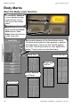
Body Marks . . . . . . . . . . . . . . . . . . . . . . . . . . . . . . . . . . . . . . . . . . . . . . . . . . . . . . . 76
Start the Body mark function . . . . . . . . . . . . . . . . . . . . . . . . . . . . . . . . . . . . . . . . 76
Select a body mark . . . . . . . . . . . . . . . . . . . . . . . . . . . . . . . . . . . . . . . . . . . . . . . . 77
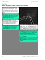
Move the Body mark and Probe Indicator . . . . . . . . . . . . . . . . . . . . . . . . . . . . . . 78
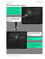
Turn or Rotate Probe Indicator . . . . . . . . . . . . . . . . . . . . . . . . . . . . . . . . . . . . . . . 79
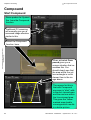
Compound . . . . . . . . . . . . . . . . . . . . . . . . . . . . . . . . . . . . . . . . . . . . . . . . . . . . . . . . 80
Start Compound . . . . . . . . . . . . . . . . . . . . . . . . . . . . . . . . . . . . . . . . . . . . . . . . . . 80
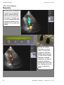
Color Flow Mapping . . . . . . . . . . . . . . . . . . . . . . . . . . . . . . . . . . . . . . . . . . . . . . . . 81
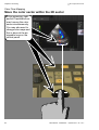
Start Color Flow in 2D mode . . . . . . . . . . . . . . . . . . . . . . . . . . . . . . . . . . . . . . . . 81
User Manual - FA092423 L - System FiVe - sw. 1.9.x
Intro-7
INTRODUCTION
GE Vingmed Ultrasound
Move the color sector within the 2D sector . . . . . . . . . . . . . . . . . . . . . . . . . . . . . . 82
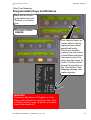
Programmable Keys and Rotaries . . . . . . . . . . . . . . . . . . . . . . . . . . . . . . . . . . . . 83
Color map selection . . . . . . . . . . . . . . . . . . . . . . . . . . . . . . . . . . . . . . . . . . . . . . . 84
Invert color map . . . . . . . . . . . . . . . . . . . . . . . . . . . . . . . . . . . . . . . . . . . . . . . . . . 85
Region of interest handling . . . . . . . . . . . . . . . . . . . . . . . . . . . . . . . . . . . . . . . . . . 86
Tissue priority . . . . . . . . . . . . . . . . . . . . . . . . . . . . . . . . . . . . . . . . . . . . . . . . . . . . 87
Baseline . . . . . . . . . . . . . . . . . . . . . . . . . . . . . . . . . . . . . . . . . . . . . . . . . . . . . . . . 88
Variance . . . . . . . . . . . . . . . . . . . . . . . . . . . . . . . . . . . . . . . . . . . . . . . . . . . . . . . . 89
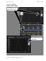
How Color Flow Mapping works . . . . . . . . . . . . . . . . . . . . . . . . . . . . . . . . . . . . . . 90
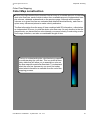
Color Map construction . . . . . . . . . . . . . . . . . . . . . . . . . . . . . . . . . . . . . . . . . . . . . 91
The Spectral Estimate . . . . . . . . . . . . . . . . . . . . . . . . . . . . . . . . . . . . . . . . . . . . . . 92
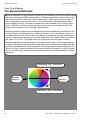
Assigning Colors and unwrapping the Color Wheel . . . . . . . . . . . . . . . . . . . . . . . 93
Disturbed Flow Indicator . . . . . . . . . . . . . . . . . . . . . . . . . . . . . . . . . . . . . . . . . . . . 94
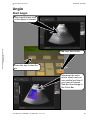
Angio . . . . . . . . . . . . . . . . . . . . . . . . . . . . . . . . . . . . . . . . . . . . . . . . . . . . . . . . . . . . .95
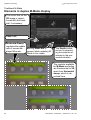
Start Angio . . . . . . . . . . . . . . . . . . . . . . . . . . . . . . . . . . . . . . . . . . . . . . . . . . . . . . 95
Power amplitude Doppler, Angio . . . . . . . . . . . . . . . . . . . . . . . . . . . . . . . . . . . . . 96
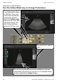
Traditional M-Mode . . . . . . . . . . . . . . . . . . . . . . . . . . . . . . . . . . . . . . . . . . . . . . . . .97
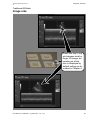
Start M-Mode, duplex view . . . . . . . . . . . . . . . . . . . . . . . . . . . . . . . . . . . . . . . . . . 97
Elements in duplex M-Mode display . . . . . . . . . . . . . . . . . . . . . . . . . . . . . . . . . . . 98
Image size . . . . . . . . . . . . . . . . . . . . . . . . . . . . . . . . . . . . . . . . . . . . . . . . . . . . . . . 99
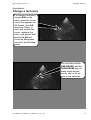
Anatomic M-Mode . . . . . . . . . . . . . . . . . . . . . . . . . . . . . . . . . . . . . . . . . . . . . . . . . .100
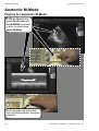
Prepare for Anatomic M-Mode . . . . . . . . . . . . . . . . . . . . . . . . . . . . . . . . . . . . . . . 100
Maneuvering the cursor line . . . . . . . . . . . . . . . . . . . . . . . . . . . . . . . . . . . . . . . . . 101
Anatomic M-Mode viewing . . . . . . . . . . . . . . . . . . . . . . . . . . . . . . . . . . . . . . . . . . 102
About… . . . . . . . . . . . . . . . . . . . . . . . . . . . . . . . . . . . . . . . . . . . . . . . . . . . . . . . . . 103
Color M-Mode . . . . . . . . . . . . . . . . . . . . . . . . . . . . . . . . . . . . . . . . . . . . . . . . . . . . . .104
Select Color M-Mode . . . . . . . . . . . . . . . . . . . . . . . . . . . . . . . . . . . . . . . . . . . . . . 104
Assignables, screen functions, live . . . . . . . . . . . . . . . . . . . . . . . . . . . . . . . . . . . . 105
Assignables, screen functions, FULL FREEZE . . . . . . . . . . . . . . . . . . . . . . . . . . 106
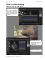
Side by side viewing . . . . . . . . . . . . . . . . . . . . . . . . . . . . . . . . . . . . . . . . . . . . . . . .107
Choose side by side view . . . . . . . . . . . . . . . . . . . . . . . . . . . . . . . . . . . . . . . . . . . 107
Doppler . . . . . . . . . . . . . . . . . . . . . . . . . . . . . . . . . . . . . . . . . . . . . . . . . . . . . . . . . . .108
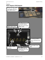
Start PW Doppler Mode . . . . . . . . . . . . . . . . . . . . . . . . . . . . . . . . . . . . . . . . . . . . 108
Start Duplex CW Doppler . . . . . . . . . . . . . . . . . . . . . . . . . . . . . . . . . . . . . . . . . . . 109
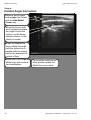
Carotid Angle Correction . . . . . . . . . . . . . . . . . . . . . . . . . . . . . . . . . . . . . . . . . . . . 110
Peak Velocity Correction . . . . . . . . . . . . . . . . . . . . . . . . . . . . . . . . . . . . . . . . . . . . 111
Sample Volume size change . . . . . . . . . . . . . . . . . . . . . . . . . . . . . . . . . . . . . . . . 112
Assignables, screen commands, live . . . . . . . . . . . . . . . . . . . . . . . . . . . . . . . . . . 113
Doppler Control descriptions . . . . . . . . . . . . . . . . . . . . . . . . . . . . . . . . . . . . . . . . . 114
Assignables, screen commands, FULL FREEZE . . . . . . . . . . . . . . . . . . . . . . . . . 115
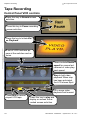
Tape Recording . . . . . . . . . . . . . . . . . . . . . . . . . . . . . . . . . . . . . . . . . . . . . . . . . . . .116
Control Panel VCR controls . . . . . . . . . . . . . . . . . . . . . . . . . . . . . . . . . . . . . . . . . 116
Chapter C117
Applications
. . . . . . . . . . . . . . . . . . . . . . . . . . . . . . . . . . . . . . . . . . . . . . . .117
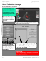
User Defaults storage . . . . . . . . . . . . . . . . . . . . . . . . . . . . . . . . . . . . . . . . . . . . . . .118
User Defaults selection . . . . . . . . . . . . . . . . . . . . . . . . . . . . . . . . . . . . . . . . . . . . . 118
Save and Recall your user default . . . . . . . . . . . . . . . . . . . . . . . . . . . . . . . . . . . . 119
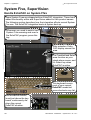
System Five, SuperVision . . . . . . . . . . . . . . . . . . . . . . . . . . . . . . . . . . . . . . . . . . . .120
Handle EchoPAC on System FiVe . . . . . . . . . . . . . . . . . . . . . . . . . . . . . . . . . . . . 120
Patient ID entry selection . . . . . . . . . . . . . . . . . . . . . . . . . . . . . . . . . . . . . . . . . . . 121
Patient ID input . . . . . . . . . . . . . . . . . . . . . . . . . . . . . . . . . . . . . . . . . . . . . . . . . . . 122
Special Setup functions . . . . . . . . . . . . . . . . . . . . . . . . . . . . . . . . . . . . . . . . . . . . 123
Footswitch activity messages . . . . . . . . . . . . . . . . . . . . . . . . . . . . . . . . . . . . . . . . 124
Willful System shut-Down with integrated Mac™ . . . . . . . . . . . . . . . . . . . . . . . . . 125
Intro-8
User Manual - FA092423 L - System FiVe - sw. 1.9.x
GE Vingmed Ultrasound
INTRODUCTION
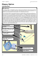
Biopsy Option . . . . . . . . . . . . . . . . . . . . . . . . . . . . . . . . . . . . . . . . . . . . . . . . . . . . . 126
Introduction . . . . . . . . . . . . . . . . . . . . . . . . . . . . . . . . . . . . . . . . . . . . . . . . . . . . . . 126
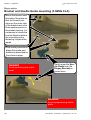
Bracket and Needle guide mounting (10MHz FLA-Feb.99) . . . . . . . . . . . . . . . . . 127
Bracket and Needle Guide mounting (3.5MHz CLA) . . . . . . . . . . . . . . . . . . . . . . 128
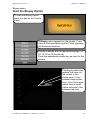
Start the Biopsy Option . . . . . . . . . . . . . . . . . . . . . . . . . . . . . . . . . . . . . . . . . . . . . 129
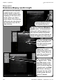
Determine Biopsy needle length . . . . . . . . . . . . . . . . . . . . . . . . . . . . . . . . . . . . . . 130
Chapter D131
Using M&A
. . . . . . . . . . . . . . . . . . . . . . . . . . . . . . . . . . . . . . . . . . . . . . . . . . 131
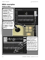
M&A examples . . . . . . . . . . . . . . . . . . . . . . . . . . . . . . . . . . . . . . . . . . . . . . . . . . . . . 132
M-Mode M&A . . . . . . . . . . . . . . . . . . . . . . . . . . . . . . . . . . . . . . . . . . . . . . . . . . . . 132
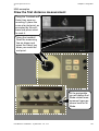
Draw the first distance measurement . . . . . . . . . . . . . . . . . . . . . . . . . . . . . . . . . . 133
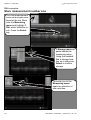
Store measurement number one . . . . . . . . . . . . . . . . . . . . . . . . . . . . . . . . . . . . . 134
Repeat a measurement . . . . . . . . . . . . . . . . . . . . . . . . . . . . . . . . . . . . . . . . . . . . 135
Store the repeated measurement . . . . . . . . . . . . . . . . . . . . . . . . . . . . . . . . . . . . . 136
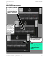
Measure 2D Area in duplex M-Mode . . . . . . . . . . . . . . . . . . . . . . . . . . . . . . . . . . 137
Complete and store 2D area measurements . . . . . . . . . . . . . . . . . . . . . . . . . . . . 138
Cardiac M&A Configuration . . . . . . . . . . . . . . . . . . . . . . . . . . . . . . . . . . . . . . . . . 139
Mode shifting during M&A . . . . . . . . . . . . . . . . . . . . . . . . . . . . . . . . . . . . . . . . . . 140
Report . . . . . . . . . . . . . . . . . . . . . . . . . . . . . . . . . . . . . . . . . . . . . . . . . . . . . . . . . . 141
VCR M&A . . . . . . . . . . . . . . . . . . . . . . . . . . . . . . . . . . . . . . . . . . . . . . . . . . . . . . . . . 142
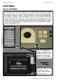
About VCR M&A . . . . . . . . . . . . . . . . . . . . . . . . . . . . . . . . . . . . . . . . . . . . . . . . . . 142
2D VCR Calibrate . . . . . . . . . . . . . . . . . . . . . . . . . . . . . . . . . . . . . . . . . . . . . . . . 143
Enter the 2D calibration data . . . . . . . . . . . . . . . . . . . . . . . . . . . . . . . . . . . . . . . . 144
Ready for 2D M&A . . . . . . . . . . . . . . . . . . . . . . . . . . . . . . . . . . . . . . . . . . . . . . . . 145
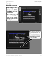
2D/M-Mode calibration . . . . . . . . . . . . . . . . . . . . . . . . . . . . . . . . . . . . . . . . . . . . . 146
Calibrate the 2D area . . . . . . . . . . . . . . . . . . . . . . . . . . . . . . . . . . . . . . . . . . . . . . 147
Mark the M-Mode area . . . . . . . . . . . . . . . . . . . . . . . . . . . . . . . . . . . . . . . . . . . . . 148
Calibrate the M-Mode area Time scale . . . . . . . . . . . . . . . . . . . . . . . . . . . . . . . . 149
Calibrate the M-Mode area depth scale . . . . . . . . . . . . . . . . . . . . . . . . . . . . . . . . 150
M&A Package for application change . . . . . . . . . . . . . . . . . . . . . . . . . . . . . . . . . . 151
The Calibration Marker . . . . . . . . . . . . . . . . . . . . . . . . . . . . . . . . . . . . . . . . . . . . 152
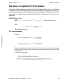
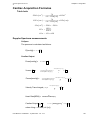
Cardiac Acquisition Formulas . . . . . . . . . . . . . . . . . . . . . . . . . . . . . . . . . . . . . . . . 153
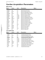
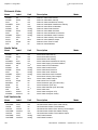
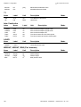
Cardiac Acquisition Parameters . . . . . . . . . . . . . . . . . . . . . . . . . . . . . . . . . . . . . . 157
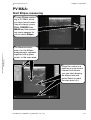
PV M&A: . . . . . . . . . . . . . . . . . . . . . . . . . . . . . . . . . . . . . . . . . . . . . . . . . . . . . . . . . . 161
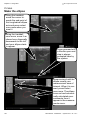
Start Ellipse measuring . . . . . . . . . . . . . . . . . . . . . . . . . . . . . . . . . . . . . . . . . . . . . 161
Make the ellipse . . . . . . . . . . . . . . . . . . . . . . . . . . . . . . . . . . . . . . . . . . . . . . . . . . 162
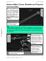
Volume M&A, Tissue, Bladder and Thyroid . . . . . . . . . . . . . . . . . . . . . . . . . . . . . 163
Start Volume M&A . . . . . . . . . . . . . . . . . . . . . . . . . . . . . . . . . . . . . . . . . . . . . . . . 163
Save Volume M&A Results . . . . . . . . . . . . . . . . . . . . . . . . . . . . . . . . . . . . . . . . . 164
Volume Formulas: . . . . . . . . . . . . . . . . . . . . . . . . . . . . . . . . . . . . . . . . . . . . . . . . 164
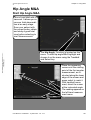
Hip Angle M&A . . . . . . . . . . . . . . . . . . . . . . . . . . . . . . . . . . . . . . . . . . . . . . . . . . . . . 165
Start Hip Angle M&A . . . . . . . . . . . . . . . . . . . . . . . . . . . . . . . . . . . . . . . . . . . . . . . 165
Complete Measurements and Save results . . . . . . . . . . . . . . . . . . . . . . . . . . . . . 166
OBGYN M&A Setup . . . . . . . . . . . . . . . . . . . . . . . . . . . . . . . . . . . . . . . . . . . . . . . . . 167
Select the Measurement type . . . . . . . . . . . . . . . . . . . . . . . . . . . . . . . . . . . . . . . . 167
Do the Measurement . . . . . . . . . . . . . . . . . . . . . . . . . . . . . . . . . . . . . . . . . . . . . . 168
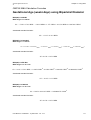
OBGYN M&A Calculation Formulas . . . . . . . . . . . . . . . . . . . . . . . . . . . . . . . . . . . . 169
Gestational Age (week+days) using Femur Length . . . . . . . . . . . . . . . . . . . . . . . 169
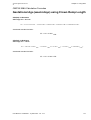
Gestational Age (week+days) using Biparietal Diameter . . . . . . . . . . . . . . . . . . . 171
Gestational Age (week+days) using Crown Rump Length . . . . . . . . . . . . . . . . . . 173
Gestational Age (week+days) using Head Circumference . . . . . . . . . . . . . . . . . . 174
Gestational Age (week+days) using Abdominal Circumference . . . . . . . . . . . . . 175
Gestational Age (week+days) using Humerus Length . . . . . . . . . . . . . . . . . . . . . 177
Gestational Age (week+days) using Ulna Length . . . . . . . . . . . . . . . . . . . . . . . . 178
User Manual - FA092423 L - System FiVe - sw. 1.9.x
Intro-9
GE Vingmed Ultrasound
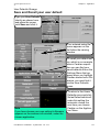
INTRODUCTION
Measurements & Ratios . . . . . . . . . . . . . . . . . . . . . . . . . . . . . . . . . . . . . . . . . . . . 179
Cardiovascular Acquisition Formulas . . . . . . . . . . . . . . . . . . . . . . . . . . . . . . . . . .180
Chapter E183
Installation & Maintenance
. . . . . . . . . . . . . . . . . . . . . . . . . .183
System FiVe Installation . . . . . . . . . . . . . . . . . . . . . . . . . . . . . . . . . . . . . . . . . . . . .184
Preventive User Maintenance . . . . . . . . . . . . . . . . . . . . . . . . . . . . . . . . . . . . . . . . .184
Chapter F187
Warnings
. . . . . . . . . . . . . . . . . . . . . . . . . . . . . . . . . . . . . . . . . . . . . . . . . . . .187
Electrical Power Safety . . . . . . . . . . . . . . . . . . . . . . . . . . . . . . . . . . . . . . . . . . . . . 188
Electrical Shock Hazards . . . . . . . . . . . . . . . . . . . . . . . . . . . . . . . . . . . . . . . . . . . 188
Explosion Hazards . . . . . . . . . . . . . . . . . . . . . . . . . . . . . . . . . . . . . . . . . . . . . . . . 188
Mechanical Safety . . . . . . . . . . . . . . . . . . . . . . . . . . . . . . . . . . . . . . . . . . . . . . . . . 188
AIUM statement on clinical safety. . . . . . . . . . . . . . . . . . . . . . . . . . . . . . . . . . . . . 189
AIUM Statement on Mammalian in Vivo Ultrasonic Biological Effects . . . . . . . . . 189
GE Vingmed Ultrasound Safety statement . . . . . . . . . . . . . . . . . . . . . . . . . . . . . . 189
The GE Vingmed Ultrasound Patent Rights . . . . . . . . . . . . . . . . . . . . . . . . . . . . .190
List of GE Vingmed Ultrasound’s Patents . . . . . . . . . . . . . . . . . . . . . . . . . . . . . . . 190
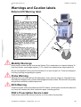
Warnings and Caution labels . . . . . . . . . . . . . . . . . . . . . . . . . . . . . . . . . . . . . . . . .193
External I/O Warning label . . . . . . . . . . . . . . . . . . . . . . . . . . . . . . . . . . . . . . . . . . 193
Mobility Warnings . . . . . . . . . . . . . . . . . . . . . . . . . . . . . . . . . . . . . . . . . . . . . . . . . 193
Probe Warning . . . . . . . . . . . . . . . . . . . . . . . . . . . . . . . . . . . . . . . . . . . . . . . . . . . 193
ECG Warning . . . . . . . . . . . . . . . . . . . . . . . . . . . . . . . . . . . . . . . . . . . . . . . . . . . . 193
FDA’s Prescription Device Label . . . . . . . . . . . . . . . . . . . . . . . . . . . . . . . . . . . . . 193
Monitors . . . . . . . . . . . . . . . . . . . . . . . . . . . . . . . . . . . . . . . . . . . . . . . . . . . . . . . . 194
Printers, B/W and Color . . . . . . . . . . . . . . . . . . . . . . . . . . . . . . . . . . . . . . . . . . . . 197
Video Cassette Recorders . . . . . . . . . . . . . . . . . . . . . . . . . . . . . . . . . . . . . . . . . . 198
Chapter G199
Specifications
. . . . . . . . . . . . . . . . . . . . . . . . . . . . . . . . . . . . . . . . . . . . .199
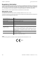
Regulatory Information . . . . . . . . . . . . . . . . . . . . . . . . . . . . . . . . . . . . . . . . . . . . . 200
Standards used . . . . . . . . . . . . . . . . . . . . . . . . . . . . . . . . . . . . . . . . . . . . . . . . . . . 200
. . . . . . . . . . . . . . . . . . . . . . . . . . . . . . . . . . . . . . . . . . . . . . . . . . . . . . . . . . . . . . . . . .200
System Five
. . . . . . . . . . . . . . . . . . . . . . . . . . . . . . . . . . . . . . . . . . . . . . . .201
System Architecture . . . . . . . . . . . . . . . . . . . . . . . . . . . . . . . . . . . . . . . . . . . . . . . 201
Data Acquisition . . . . . . . . . . . . . . . . . . . . . . . . . . . . . . . . . . . . . . . . . . . . . . . . . . 201
Data Processing . . . . . . . . . . . . . . . . . . . . . . . . . . . . . . . . . . . . . . . . . . . . . . . . . . 201
Display Replay™ . . . . . . . . . . . . . . . . . . . . . . . . . . . . . . . . . . . . . . . . . . . . . . . . . 201
Display Annotations . . . . . . . . . . . . . . . . . . . . . . . . . . . . . . . . . . . . . . . . . . . . . . . 201
Tissue Imaging . . . . . . . . . . . . . . . . . . . . . . . . . . . . . . . . . . . . . . . . . . . . . . . . . . . 201
M-mode . . . . . . . . . . . . . . . . . . . . . . . . . . . . . . . . . . . . . . . . . . . . . . . . . . . . . . . . . 202
Color Doppler . . . . . . . . . . . . . . . . . . . . . . . . . . . . . . . . . . . . . . . . . . . . . . . . . . . . 202
Color Doppler Imaging . . . . . . . . . . . . . . . . . . . . . . . . . . . . . . . . . . . . . . . . . . . . . 202
Color Angio (Color Intensity Imaging) . . . . . . . . . . . . . . . . . . . . . . . . . . . . . . . . . . 203
Color M-mode . . . . . . . . . . . . . . . . . . . . . . . . . . . . . . . . . . . . . . . . . . . . . . . . . . . . 203
Spectral Doppler . . . . . . . . . . . . . . . . . . . . . . . . . . . . . . . . . . . . . . . . . . . . . . . . . . 203
PW / HPRF Doppler . . . . . . . . . . . . . . . . . . . . . . . . . . . . . . . . . . . . . . . . . . . . . . . 203
CW Doppler . . . . . . . . . . . . . . . . . . . . . . . . . . . . . . . . . . . . . . . . . . . . . . . . . . . . . 203
Physiological Traces . . . . . . . . . . . . . . . . . . . . . . . . . . . . . . . . . . . . . . . . . . . . . . . 203
Analysis Program . . . . . . . . . . . . . . . . . . . . . . . . . . . . . . . . . . . . . . . . . . . . . . . . . 203
Image Memory . . . . . . . . . . . . . . . . . . . . . . . . . . . . . . . . . . . . . . . . . . . . . . . . . . . 204
Intro-10
User Manual - FA092423 L - System FiVe - sw. 1.9.x
GE Vingmed Ultrasound
INTRODUCTION
Advanced Options . . . . . . . . . . . . . . . . . . . . . . . . . . . . . . . . . . . . . . . . . . . . . . . . 204
Indications for use . . . . . . . . . . . . . . . . . . . . . . . . . . . . . . . . . . . . . . . . . . . . . . . . . . 207
Contraindication: . . . . . . . . . . . . . . . . . . . . . . . . . . . . . . . . . . . . . . . . . . . . . . . . . . . 207
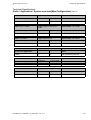
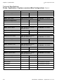
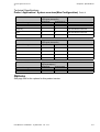
Probe / Application / System overview(Max.Configuration) . . . . . . . . . . . . . . . . 208
Options . . . . . . . . . . . . . . . . . . . . . . . . . . . . . . . . . . . . . . . . . . . . . . . . . . . . . . . . . 217
Guidelines for Fetal use . . . . . . . . . . . . . . . . . . . . . . . . . . . . . . . . . . . . . . . . . . . . 218
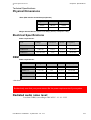
Physical Dimensions . . . . . . . . . . . . . . . . . . . . . . . . . . . . . . . . . . . . . . . . . . . . . . 219
Electrical Specifications . . . . . . . . . . . . . . . . . . . . . . . . . . . . . . . . . . . . . . . . . . . . 219
REM . . . . . . . . . . . . . . . . . . . . . . . . . . . . . . . . . . . . . . . . . . . . . . . . . . . . . . . . . . . 219
Radiated audio noise level: . . . . . . . . . . . . . . . . . . . . . . . . . . . . . . . . . . . . . . . . . 219
Environmental conditions . . . . . . . . . . . . . . . . . . . . . . . . . . . . . . . . . . . . . . . . . . . 220
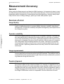
Measurement Accuracy . . . . . . . . . . . . . . . . . . . . . . . . . . . . . . . . . . . . . . . . . . . . . 221
General . . . . . . . . . . . . . . . . . . . . . . . . . . . . . . . . . . . . . . . . . . . . . . . . . . . . . . . . . 221
Sources of error . . . . . . . . . . . . . . . . . . . . . . . . . . . . . . . . . . . . . . . . . . . . . . . . . . 221
Optimizing Measurement Accuracy . . . . . . . . . . . . . . . . . . . . . . . . . . . . . . . . . . . 222
Measurement Uncertainties . . . . . . . . . . . . . . . . . . . . . . . . . . . . . . . . . . . . . . . . . 223
Chapter H227
Symbols
. . . . . . . . . . . . . . . . . . . . . . . . . . . . . . . . . . . . . . . . . . . . . . . . . . . . . 227
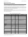
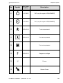
System Symbols . . . . . . . . . . . . . . . . . . . . . . . . . . . . . . . . . . . . . . . . . . . . . . . . . . . 228
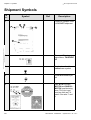
Shipment Symbols . . . . . . . . . . . . . . . . . . . . . . . . . . . . . . . . . . . . . . . . . . . . . . . . . 230
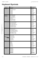
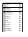
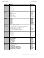
Keyboard Symbols . . . . . . . . . . . . . . . . . . . . . . . . . . . . . . . . . . . . . . . . . . . . . . . . . 232
Chapter L239
Index
. . . . . . . . . . . . . . . . . . . . . . . . . . . . . . . . . . . . . . . . . . . . . . . . . . . . . . . . . . 239
ADDENDUM . . . . . . . . . . . . . . . . . . . . . . . . . . . . . . . . . . . . . . . . . . . . . . . . . . . . . . . 247
LABEL for locating DISASSEMBLY PROCEDURE . . . . . . . . . . . . . . . . . . . . . . . 247
User Manual - FA092423 L - System FiVe - sw. 1.9.x
Intro-11
INTRODUCTION
Intro-12
GE Vingmed Ultrasound
User Manual - FA092423 L - System FiVe - sw. 1.9.x
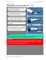
Chapter A
System Preparations
This chapter tells you about, and how to:
• Turn ON the system. . . . . . . . . . . . . . . . . . . . . . . . . . . . . . . . . . . 2
• Connect Power cable and locate Power switches . . . . . . . . . . . 2
• The Power-Up process . . . . . . . . . . . . . . . . . . . . . . . . . . . . . . . 3
• System Probes . . . . . . . . . . . . . . . . . . . . . . . . . . . . . . . . . . . . . . 4
• Patient I/O & traces setup. . . . . . . . . . . . . . . . . . . . . . . . . . . . . . 8
• Connect ECG harness. . . . . . . . . . . . . . . . . . . . . . . . . . . . . . . . 8
• Connect other trace sources . . . . . . . . . . . . . . . . . . . . . . . . . . . 16
• Wheel locking. . . . . . . . . . . . . . . . . . . . . . . . . . . . . . . . . . . . . . . . 21
• External I/O Panel . . . . . . . . . . . . . . . . . . . . . . . . . . . . . . . . . . . . 22
• Control Panel Equipment . . . . . . . . . . . . . . . . . . . . . . . . . . . . . . 24
• Headphone connection and volume adjustment . . . . . . . . . . . . 24
• Lamp Connection. . . . . . . . . . . . . . . . . . . . . . . . . . . . . . . . . . . . 25
• Screen Configuration . . . . . . . . . . . . . . . . . . . . . . . . . . . . . . . . . 26
• Start screen configuration . . . . . . . . . . . . . . . . . . . . . . . . . . . . . 26
• Configure Scanner Screen and VCR recording. . . . . . . . . . . . . 27
• Setup . . . . . . . . . . . . . . . . . . . . . . . . . . . . . . . . . . . . . . . . . . . . . .
• Start System Setup . . . . . . . . . . . . . . . . . . . . . . . . . . . . . . . . . .
• Do EchoPAC/Clipboard setup . . . . . . . . . . . . . . . . . . . . . . . . . .
• Configuration and Test. . . . . . . . . . . . . . . . . . . . . . . . . . . . . . . .
• Diagnostic Tests, Software versions, GE Service . . . . . . . . . . .
28
28
32
34
35
• Internal Patient Archive*. . . . . . . . . . . . . . . . . . . . . . . . . . . . . . .
• Do Patient information storage . . . . . . . . . . . . . . . . . . . . . . . . .
• Complete an Exam entry . . . . . . . . . . . . . . . . . . . . . . . . . . . . . .
• Do Ultrasound Image storage . . . . . . . . . . . . . . . . . . . . . . . . . .
37
38
40
41
• Image Recall . . . . . . . . . . . . . . . . . . . . . . . . . . . . . . . . . . . . . . . . 46
• System Quick Reference . . . . . . . . . . . . . . . . . . . . . . . . . . . . . . 47
Chapter A - System Preparations
GE Vingmed Ultrasound
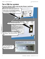
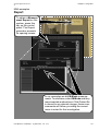
Turn ON the system
Connect Power cable and locate Power switches
Unwind this cable and connect the
plug end to a hospital grade power
source with correct Voltage and Power
consumption specifications.
Switch ON the Power here.
System FiVe is now in a Stand
by situation. The internal VCR is
ON.
To start System FiVe,
press this Stand by/
ON key once.
2
User Manual - FA092423 L - System FiVe - sw. 1.9.x
GE Vingmed Ultrasound
Chapter A - System Preparations
Turn On the system
The Power-Up process
The actions on the previous page start the power-up process, including
self-tests. During this, the
start-screen picture appears on the monitor.
IMPORTANT
Color unstableness on the
monitor picture at power
up may last as long as 10
minutes. Do not try to
correct this or do any other
monitor adjustments during this period.
When done, the screen picture
changes, the default probe, if connected, calibrates and the machine opens in the 2D scan mode.
HINT
All connected GE Vingmed Ultrasound
probes have unique identities that the
system reads at boot-up. The system
chooses the one with the lowest number as default probe.
For scanning information,
go to Chapter B.
To change settings, enter
ID etc., go to Chapter B.
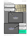
The ultrasound area has
a depth scale, a 2D sector, a tilt indicator, a greyscale bar, a time/motion
line with 1second apart
markers.
At the top left hand side of the screen, the Location name is found and below it, the Patient ID window. Find the Clipboard area for image captures to
the right of patient I/O input. Down the left edge you see scan parameters.
Down the right edge, we have the scanner info window and the paddle menu
controls.
User Manual - FA092423 L - System FiVe - sw. 1.9.x
3
GE Vingmed Ultrasound
Chapter A - System Preparations
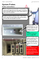
System Probes
Probe connections
Before the scanner can be used, it is necessary to
mount the Probes that are to be used. Let connected but unused Probes rest in the Probe holders at
each side of the system.
Organize all probe cabling so that it runs via the
hooks under the control panel and avoids getting
run over when the System is moved.
Connect either 1 or 2
APAT Probes, or 1 or 2
MPTE Probes and one
Doppler Probe on this
connector panel.
HINT
Available Probes are
listed on page 208.
Connect Phased Array
Probes (maximum 3) on
this connector panel.
An extra Phased array
Probe connector may be
lodged in the dummy
slot.
CAUTION
Malfunctioning or nonworking probes that
show any signs of mishandled use will not be
replaced by GE Vingmed
Ultrasound A/S.
4
User Manual - FA092423 L - System FiVe - sw. 1.9.x
GE Vingmed Ultrasound
Chapter A - System Preparations
System Probes
Change APAT Probes at Cable end
Study the connector section of the
Probe and Probe cable, and notice
how they can fit together.
To connect an APAT Probe to its cable, align the connector and receptacle and connect the cable.
After connections, the system senses
the Probe's presence, notes its imaging frequency and calibrates it.
The activated Probe frequency is on
the screen.
Release collar
To disconnect the APAT Probe from
the cable, hold the probe, take a grip
of the cable release collar and gently
free it from the Probe housing.
HINT!
Find the Probe’s part number and frequency on the colored Probe collar
and the serial number on the grey housing near the ring.
CAUTION
Use ultrasound gel during all NON-INVASIVE investigations to get the best
image views at the lowest possible Acoustic power output. For Invasive
probes consult each invasive probes manual.
User Manual - FA092423 L - System FiVe - sw. 1.9.x
5
GE Vingmed Ultrasound
Chapter A - System Preparations
System Probes
System-Connect Probe cabling
To connect APAT or MPTE Probes, align the
connector with the socket and insert it.
To disconnect one of these, press this part of
the connector gently downwards and extract
the connector from the socket.
HINT1
You may change APAT Probe types at the Probe end of the cable, without
removing the socket end. See previous page.
To connect a Phased Array Probe, align
the connector with the socket, insert the
connector into the socket so that the connector center pin centers on the socket
center. To fasten the connector, rotate
the lock handle 90° clockwise.
Disconnect a probe connector in the
reverse order.
HINT2
After Probe changing at these locations, always select the (new) activated Probe on the
PROBE MENU. See next page.
6
User Manual - FA092423 L - System FiVe - sw. 1.9.x
GE Vingmed Ultrasound
Chapter A - System Preparations
System Probes
Active Probe and Application Selection
Press this key to display the Probe menu
which contains an overview of the connected
Probes.
This Probe menu appears on the screen.
Its setup contents are
Probe type dependent.
With the trackball, move activity onto the
menu and onto the desired Probe. Beside
the Probe menu, an Application menu
appears shortly after.
To select a Probe and
Application, highlight it
and press the Select
key.
Exit from Probe and
Application Menus
with Cancel.
User Manual - FA092423 L - System FiVe - sw. 1.9.x
7
GE Vingmed Ultrasound
Chapter A - System Preparations
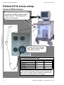
Patient I/O & traces setup
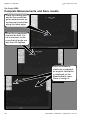
Connect ECG harness
The Patient I/O panel is here. You may
connect four different patient Input/
Output sources. These appear as
traces on the screen.
Connect the ECG harness
here. There are two types,
either Blue or Grey.
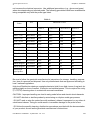
ECG Electrode placement table
Physical placement
“Blue cable”
“Grey cable”
Right arm
RA
R
Left leg
LL
L
Left arm *)
LA
N
*) The left arm ECG pad connection is the reference electrode. Use it as this in order to remove unwanted electrical noise that is detected in the ECG signal.
8
User Manual - FA092423 L - System FiVe - sw. 1.9.x
GE Vingmed Ultrasound
Chapter A - System Preparations
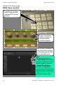
Patient I/O & traces setup
Screen changes after ECG connection
In 2D tissue mode, with
no ECG trace, the
screen may look like
this.
WARNING!
To obtain the correct isolation on the patient I/O only one connection
(i.e.ECG, Phono, Pulse pressure or Respiration) must be used on the Scanner at a time.This means that in normal use the Scanner will have three open
connectors. The System User must ensure that the patient cannot touch the
open connectors.
In Cardiac 2D Acquisition, when ECG wiring is
strapped to a patient
and connected to the
system, a trace from it
appears as shown here.
Hint
In Peripheral Vascular acquisition, the display of
traces is off but may be reconfigured to be on.
User Manual - FA092423 L - System FiVe - sw. 1.9.x
9
Chapter A - System Preparations
GE Vingmed Ultrasound
Patient I/O & traces setup
ECG trace control
To access the Physiological trace controls,
including ECG, press
this key.
At the re-programmables on the control panel these
functions appear.
The screen is redrawn,
and some Trace controls
are available on the Paddle-controlled menu.
Hint
Screen Functions are:
- Timer Delay, Each step to
the right lengthens time between triggers, when on.
- Keep Cont.frames,
On/Off, for keeping the
continually memory stored
frames before switching to
triggered scan or just overwriting the stored data.
10
User Manual - FA092423 L - System FiVe - sw. 1.9.x
GE Vingmed Ultrasound
Chapter A - System Preparations
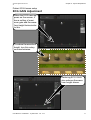
Patient I/O & traces setup
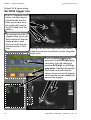
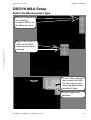
ECG GAIN Adjustment
When the ECG trace appears on the screen, it
has a setting of maximum gain and the waveform height looks similar
to this.
To reduce the waveform
height, turn this rotary
counterclockwise.
Reducing ECG GAIN
also reduces the waveform height shown.
User Manual - FA092423 L - System FiVe - sw. 1.9.x
11
Chapter A - System Preparations
GE Vingmed Ultrasound
Patient I/O & traces setup
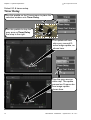
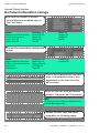
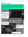
Set ECG trigger one
In ECG Triggered acquisition, live scan data is
synchronized with the
heart cycle trace from
the continually oncoming ECG data from the
patient.
The systems dual ECG
triggers allow you to pinpoint events for Specific
image display, each
time you reach the pinpointed section of the
Through this you can relate seen heart abnorloop.
mality occurrences to positions in time, along the
heart cycle.
Press the ECG trigging key
once and Turn ECGTrig1slightly
clockwise. See the change at
position ECG trig1 on the Trigging menu. See also the vertical
trig marker and note that the
shown screen scene will appear
each time the screen update line
passes the triggers.
12
User Manual - FA092423 L - System FiVe - sw. 1.9.x
GE Vingmed Ultrasound
Chapter A - System Preparations
Patient I/O & traces setup
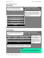
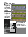
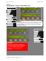
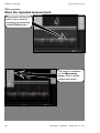
Set ECG trigger two
To set a second trigger
to capture for display
another occurrence,
rotate this rotary clockwise. Notice the
change in the below
menu position ECG
Trig2. See also the
ECG trig2 marker and
the image occurrence it
represents.
Your acquisition is now ECG controlled. The first trigger updates your displayed image 13 milliseconds after each R wave. The second trigger updates your image 33 milliseconds after each R wave.
User Manual - FA092423 L - System FiVe - sw. 1.9.x
13
GE Vingmed Ultrasound
Chapter A - System Preparations
Patient I/O & traces setup
Timer Delay
Use this paddle on the Traces menu to place the
selection window onto Timer Delay.
Use this paddle to step the
gray area on Timer Delay
one step to the right.
The update will now
skip every second Rwave Image update, as
shown here.
Step the gray area another step. The update
passes two R-waves before image update
shown here.
14
User Manual - FA092423 L - System FiVe - sw. 1.9.x
GE Vingmed Ultrasound
Chapter A - System Preparations
Patient I/O & traces setup
Timer Trigging
To doTimerTrigging,
press this key ON.
The Timer trigging
markers appear as
specified in Trace info
window shown below.
Rotate this rotary clockwise to increase delay
between image triggered updates shown
here.
User Manual - FA092423 L - System FiVe - sw. 1.9.x
15
GE Vingmed Ultrasound
Chapter A - System Preparations
Patient I/O & traces setup
Connect other trace sources
Besides the ECG source, connect a Heart
microphone source, a Breath indicator
source and one Pressure/Pulse device
source at the other sockets.
Heart microphones, Breath indicators and
Pressure/Pulse devices are available options
from the manufacturer.
Press this key to select a trace from a
connected source for
display on the image.
A Trace menu appears somewhere on the screen.
Here, it appears in the Paddle (see below) controlled area.
Moves select-window Up and Down
the Menu.
16
Switches traces On-Off,
sets gain levels and positions traces on screen.
User Manual - FA092423 L - System FiVe - sw. 1.9.x
GE Vingmed Ultrasound
Chapter A - System Preparations
Patient I/O & traces setup
Trace area size
To set or change the Trace area size
on the screen, click ON/OFF Small,
Mediur, Large or Full.
With Large area chosen the Traces
menu has these additional setting options, the same as the Small Area.
Using paddle controls, connect
and switch ON Phono and Resp
traces.
Adjust their settings,
still using the Paddle
controls, and the result
will resemble the
screen situation shown
here.
User Manual - FA092423 L - System FiVe - sw. 1.9.x
17
Chapter A - System Preparations
GE Vingmed Ultrasound
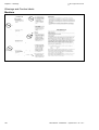
Footswitch
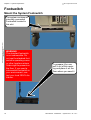
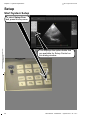
Mount the System Footswitch
The system contains an
internally connected
Footswitch located in
this slot.
WARNING
The standard footswitch
is not submersible. Do
not use the standard footswitch in operating rooms
or other locations where
fluids might be present on
the floor. If you need a
submersible footswitch in
your environment, contact your local GEVU distributor.
18
To prepare it for use,
pull it out of this opening and place it on the
floor where you need it.
User Manual - FA092423 L - System FiVe - sw. 1.9.x
GE Vingmed Ultrasound
Chapter A - System Preparations
Footswitch
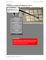
Finding the Footswitch Mapping option
To do Footswitch
mapping, press this
key to display the Setup
menu.
IMPORTANT
Footswitch mapping, as described here, will always
relate to the presently active probe. When you save
a Footswitch setup, it relates to this only. Other
probes need new setup rounds.
User Manual - FA092423 L - System FiVe - sw. 1.9.x
19
Chapter A - System Preparations
GE Vingmed Ultrasound
Footswitch
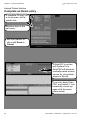
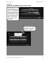
Footswitch Mapping
Place the cursor onto
Footswitch Mapping
and press the Select area. To the right of the
Setup menu the Footswitch Mapping menu
appears.
Using the Trackball, place the cursor within each switch menu and
click select your switch setup
shown above and described below.
To FULL FREEZE the scan function, press and release the center
foot control. Press and release it
once more to continue scanning.
Press and release the right hand
foot control to IMAGE STORE
from the Acquisition to the system
Clipboard.
To REC/PAUSE tape recording,
press and release this foot
switch. Press and release it
again to continue tape recording.
20
User Manual - FA092423 L - System FiVe - sw. 1.9.x
GE Vingmed Ultrasound
Chapter A - System Preparations
Wheel locking
Lock, Unlock scanner wheels
In upper position the rear wheels are
direction locked but rotate freely
At half way down
position all
wheels turn and
rotate freely.
At the lowest position the
system is parked and
breaks are active on bothrear wheels.
User Manual - FA092423 L - System FiVe - sw. 1.9.x
21
Chapter A - System Preparations
GE Vingmed Ultrasound
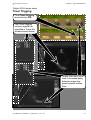
External I/O Panel
System I/O panel location
The External I/O connector
panel is located here on the
system.The panel sockets
are identified on the next
page.
WARNING
The External input and output sockets are not electrically isolated from the
rest of the circuitry within System FiVe. Any instruments which are connected to System FiVe via these inputs or outputs must conform to standard
hospital electrical safety and leakage requirements. It is the responsibility
of the user to ensure that this important safety requirement is met in all cases. When connecting the System FiVe to a non-isolated device, a Hospital
grade isolation transformer should be used to supply the mains power.
A-22
User Manual - FA092423 L - System FiVe - sw. 1.9.x
GE Vingmed Ultrasound
Chapter A - System Preparations
External I/O Panel
Socket identifications
GR(aphic) RS232 and CPU RS232 sockets.
ETHERNET** socket. Used for communication with
EchoPAC stand-alone.
SVHS OUT and SVHS IN sockets for Super VHS
VCR connection.
COMP OUT and COMP IN connectors. COMP OUT
is used by EchoPAC. COMP IN can be used by a
great variety of sources, such as display of an X-Ray
picture etc.
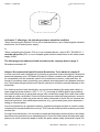
**IMPORTANT
Connect the Ethernet interface cable (FA200460)
between the External I/O socket and the Ethernet
adapter and slide latch these together. Arrange
cabling to avoid any possible damages. When a
patient is connected to the System, always use
the Ethernet Isolation Box (P/N:EP200032, as
shown to the right) to obtain correct isolation.
Four Analog input sockets. Can be used for auxiliary
traces.
ECG TRIG OUT socket.
Output sockets for color printers.
User Manual - FA092423 L - System FiVe - sw. 1.9.x
A-23
GE Vingmed Ultrasound
Chapter A - System Preparations
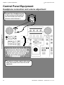
Control Panel Equipment
Headphone connection and volume adjustment
Connect the Headphone jack
to this system socket and adjust the sound level with the
volume control above it.
AUDIO
HEADPHONE
INFO
BODY
MARK
HELP
LINE
ERASE
TEXT
ZOOM
PAGE
ERASE
ACTIVE
MODE
ILLUM.
SCREEN
CONFIG
PHYS.
TRACE
REC.
GAIN
SPLIT
SCREEN
2D
DEPTH
The above volume control also regulates the sound level from the loudspeakers.
24
User Manual - FA092423 L - System FiVe - sw. 1.9.x
GE Vingmed Ultrasound
Chapter A - System Preparations
Control Panel Equipment
Lamp Connection
Connect the plug end of
the system lamp into this
socket and adjust the emitted light level with the ILLUM. Control directly
below it.
AUDIO
HEADPHONE
INFO
BODY
MARK
HELP
LINE
ERASE
TEXT
ZOOM
PAGE
ERASE
ACTIVE
MODE
ILLUM.
SCREEN
CONFIG
PHYS.
TRACE
REC.
GAIN
SPLIT
SCREEN
2D
DEPTH
HINT
The lamp is governed by a light sensor on the control panel. When it
gets darker the lamp is lit. If an increase of emitted light from other
sources prevail the lamp is switched off.
User Manual - FA092423 L - System FiVe - sw. 1.9.x
25
GE Vingmed Ultrasound
Chapter A - System Preparations
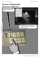
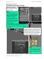
Screen Configuration
Start screen configuration
To select screen configuration, press this key
once.
This displays the options that are
available for screen configuration on
this dialog window.
26
User Manual - FA092423 L - System FiVe - sw. 1.9.x
GE Vingmed Ultrasound
Chapter A - System Preparations
Screen Configurations
Configure Scanner Screen and VCR recording
For description of Trace
Sizes see page A-17.
To switch On/Off traces
select this.
To choose a Small trace
area select this one On.
Select a medium sized
area with this one.
Select a large sized
area with this one.
To reserve the complete
ultrasound area for traces, select Full.
Hide or Show scan parameters on tape recordings.
Hide or Show Patient
name on tape recordings.
Displayduplex mode
data Side By Side or
Over/Under each.
Switch ON/OFF the display
of KHz on a Doppler scale.
Change image
size here.
Hint!
The Small trace area is default
chosen at boot-up.
User Manual - FA092423 L - System FiVe - sw. 1.9.x
27
Chapter A - System Preparations
GE Vingmed Ultrasound
Setup
Start System Setup
To select Setup Control, press this key once.
This displays the option-fields that
are available for Setup Control on
this dialog window.
28
User Manual - FA092423 L - System FiVe - sw. 1.9.x
GE Vingmed Ultrasound
Chapter A - System Preparations
Setup
Get a Setup Menu overview
Here, you have an overview of the options on
the Setup menu. Change the setup whenever
you change probes or application.
Done exits you from the setup
menu. Changes are automatically saved on exit by Done.
Most of these options have their own separate
descriptions on the following pages.
Footswitch mapping is described in the Footswitch mounting description found on page 20.
User Manual - FA092423 L - System FiVe - sw. 1.9.x
29
Chapter A - System Preparations
GE Vingmed Ultrasound
Setup
User Interface
Do your User Interface
setups on this configuration screen. It allows you
to configure Freeze and
Autofreeze functionality.
30
User Manual - FA092423 L - System FiVe - sw. 1.9.x
GE Vingmed Ultrasound
Chapter A - System Preparations
Setup
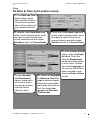
Do Date & Time and Location setup
On the Date and Time
Setup dialog set the
Date and time of day in
a format that is selectable on the Location dialog, described below.
To set date, make New Date area
active, erase contents within, enter
new date in same format as removed contents and click-select
Set date to start it at Current Date.
To enter Hospital
and Department
names, make each
area active, erase
any wrong contents,
type the correct
names at each.
To set time, make New Time area
active, erase contents within, enter
new date in same format as removed contents and click-select
Set time to start it at Current Time.
To choose a Language
or Date and Time Format for system display,
place the cursor within
each area and click-select the correct language and Date and
Time format.
User Manual - FA092423 L - System FiVe - sw. 1.9.x
On the Location Setup
dialog, enter the Hospital name. Enter the
Hospital Department
name where the system
is to be used. Choose
the native Language of
the country that the hospital is located in and
choose a Date and time
format.
31
GE Vingmed Ultrasound
Chapter A - System Preparations
Setup
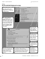
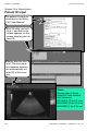
Do EchoPAC/Clipboard setup
Click-select here to display the options for
EchoPAC or Clipboard
configuration.
The Image Store
keys destination configuration area where
you can set the button
to do one of four different storage methods available within
this area.
Here you can
define what to
store with the
Image Store key.
Set the time interval (ms) between 2D frames
when storing
Doppler spectrum or M-mode.
Set Time span (ms)
to transfer/store in
live 2D-mode without ECG.
Insert the Trig point offset in ms at this option to
define where on the
QRS the ECG trigger
point is.
32
To set the Image format for transfers
to EchoPAC, select Preview
cineloop before transfer, RGB transfer of single frame (image area) or
RGB half resolution(full screen).
Set number of
heartcycles to
transfer/store, or
Select single frame
transfer/store.
User Manual - FA092423 L - System FiVe - sw. 1.9.x
GE Vingmed Ultrasound
Chapter A - System Preparations
Setup
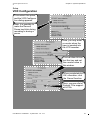
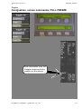
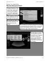
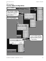
VCR Configuration
Click-select this option,
and the VCR Configuration dialog appears.
Here, it is possible to
make the Record/
Pause key blink during
recording or during a
pause.
Here, you may enter
a counter when the
tape is inserted into
the VCR recorder.
You can also click select this key and set
the counter value in
this window.
When completed click
OK, otherwise, click
the Cancel function.
Here, you see a list of
System FiVe supported VCRs.
User Manual - FA092423 L - System FiVe - sw. 1.9.x
33
Chapter A - System Preparations
GE Vingmed Ultrasound
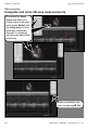
Setup
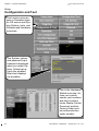
Configuration and Test
This function gives access to Password input
for GE service and System Options, tests, and
Software and Hardware
overviews.
The System options
and password input
example is displayed
when you select Options. Yellow text reflects the installed,
Black text displays
the available.
This is the Hardware
Module overview. Actives you module
names, part numbers
and their revisions
levels, Master Control
Document revision,
Factory Order number and production
series number.
34
User Manual - FA092423 L - System FiVe - sw. 1.9.x
GE Vingmed Ultrasound
Chapter A - System Preparations
Setup
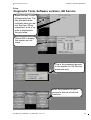
Diagnostic Tests, Software versions, GE Service
Select this key to start
a Diagnostics test. The
test proceeds automatically when you select Run test. When
completed, a list of results is displayed in
the grey area.
Select SW to display
the system sw versions.
This is the password access
to the system for GE Service
personnel only.
Enter the password to gain
access to this set of service
functions
User Manual - FA092423 L - System FiVe - sw. 1.9.x
35
GE Vingmed Ultrasound
Chapter A - System Preparations
Setup
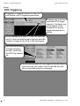
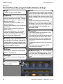
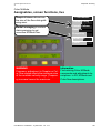
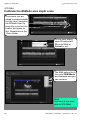
ECG Triggering
Triggering is a special function for the Contrast Option in ECG triggered acquisition.
It allows you to set two
individual ECG trigger
intervals. Configure one
of the pedals on the
Footswitch to quickly
toggle between the intervals.
In our example let’s enter 3 in the first input box
and 5 in the next which means that we want the
system to trigger at the third or fifth heartcycle.
To make the left pedal toggle between
the two, switch ON
the ECG trig Interval
sw.
The left switch pedal will now trigger at the third heartcycle one time you press it and on the fifth the next
time in accordance with our example.
36
User Manual - FA092423 L - System FiVe - sw. 1.9.x
GE Vingmed Ultrasound
Chapter A - System Preparations
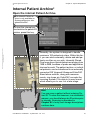
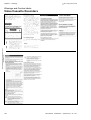
Internal Patient Archive*
Open the internal Patient Archive
*The Internal Patient archive is only available on
Systems without an integrated EchoPAC.
To start the internal patient archive for patient ID
entries, press this key.
Internally, the system is designed to handle
maximum 100 patients at a time. Within this limit, you can store externally, delete and add patients as often as you wish. Internally Stored,
Cine loops have typical data sizes ranging from
1MB to 5MB, because of probe and application
choices for each. The patient archive, or individual patients, can be transferred to an externally
connected GE Vingmed Ultrasound EchoPAC
Stand alone solution, along with measurements, cine loops etc. EchoPAC converts the
incoming System FiVe data to its own format
which allows you to use it at a later stage.
Hint
You may scan a patient without entering Patient ID. To store this however, in a retrievable
manner, you should always do ID entries prior
to storage. Scanning is described in
Chapter B. Id entry and storage descriptions
continue here.
User Manual - FA092423 L - System FiVe - sw. 1.9.x
37
GE Vingmed Ultrasound
Chapter A - System Preparations
Internal Patient Archive
Do Patient information storage
The area for Patient ID entries
where Minimum accepted input is
the Last Name.
Hints:
Maximum number of characters in text entries:
Last name: 30
First name: 30
Birthdate: 10
Patient ID: 30
Street: 20
Phone:20
City:20
State: 20
Weight:15
height:15
Zip:20
The area for examination background
entries.
Hints:
Max.Characters & entries:
4 Pop-up menus: 8 user entries each.
Operator:16
Resp Phys:16
Rep Phys:16
Diag codes:16
Echolab:20
Tape:20
ExamID:20
Counter:20
This is the Examinations overview
area. Its displayed contents, also
dependent on the input from the
above areas.
Area for free text input as Referral
reasons, Diagnosis and Comments.
INFO
All text input from keyboard. Delete text input with Backspace key.
Screen function keys described
separately on following pages.
38
User Manual - FA092423 L - System FiVe - sw. 1.9.x
GE Vingmed Ultrasound
Chapter A - System Preparations
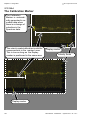
Internal Patient Archive
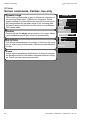
New Exam
To tell the system that you are going to do a New Examination,
click-select this screen function.
Create New Examination
On the New Exam menu that appears, use the Trackball and the
Select function to choose one of
the menu alternatives or Cancel
the activity.
Use Undefined Patient
Create New Patient
Search For Patient
Use Current Patient
Cancel
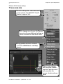
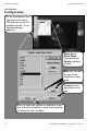
Find patient
To find a patient name stored on
your system, click-select this function.
Last Name
First Name
Examination
Hansen
Hans
01/11-1914
Wilson
Will
24/06-1939
Images
2
0
4
8
Cancel
On the patient list
that appears, use
the Trackball and
Select function to
choose the correct
patient or cancel
to exit.
A patient file similar to the one shown on the next
page, regarding your selected patient, is displayed.
Note!
If you are going to do a new examination,
find the patient via the New Exam function.
User Manual - FA092423 L - System FiVe - sw. 1.9.x
39
Chapter A - System Preparations
GE Vingmed Ultrasound
Internal Patient Archive
Complete an Exam entry
A complete ID entry, prior to an exam, will resemble this.
Minimum input is the
last name.
Exit from patient archive with Done or
Cancel.
If EchoPAC is on-line
with System FiVe,
EchoPAC will also automatically create a home
screen for your patient,
shown to the left.
If you shut down EchoPAC, and restart it, it automatically comes up
again with the same
home screen.
40
User Manual - FA092423 L - System FiVe - sw. 1.9.x
GE Vingmed Ultrasound
Chapter A - System Preparations
Internal Patient Archive
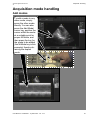
Do Ultrasound Image storage
The current patient
file’s Ultrasound image
area is here.
Hint!
As mentioned previous
you have an ultrasound
data variation between
1MB and 5MB for a 1
second cineloop from
live mode scanning. You
can transfer cine loops to
EchoPAC with related
patient archive.
You can store cine loops longer than one
second and by that larger than five MB, but it
will take a lot longer to store/recall such large
cine loops.
Use this key to do Ultrasound data
storage in frozen or live modes. The
stored file is transferred to the system
clipboard shown at the top of the illustration above and in the clipboard
area of the illustration to the left.
Hint!
Stored images in frozen
mode are approximately
50k as internally stored
files.
User Manual - FA092423 L - System FiVe - sw. 1.9.x
41
Chapter A - System Preparations
GE Vingmed Ultrasound
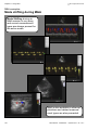
Internal Patient Archive
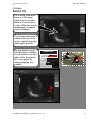
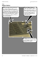
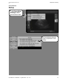
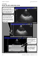
Cineloop Analysis
To do Cineloop analysis on Patient
archive stored images Click-select
the image and this Analyze key.
Your one second
cineloop appears here.
See also the red and
green cineloop end
marks along the lower
edge of the Ultrasound
area. Set-up a cineloop
or run through it with the
trackball. Press the Pat
ID key to return to the
Patient archive.
42
User Manual - FA092423 L - System FiVe - sw. 1.9.x
GE Vingmed Ultrasound
Chapter A - System Preparations
Internal Patient Archive
Add, Find, Edit, Delete Personnel…
To do this select the
Personnel… key at this
location.
The Personnel…function dialog window appears. On it you can
Find personnel, Delete
personnel, Clear personnel input from the
personnel window, Cancel personnel activity or
just exit with Done.
User Manual - FA092423 L - System FiVe - sw. 1.9.x
43
GE Vingmed Ultrasound
Chapter A - System Preparations
Internal Patient Archive
Patients list handling
To display the Archive
Patients list click-Select this key.
Use this function to handle patient file storage limits within the system (Thirty Patients). With it you can select the current, any individual or all files,
transfer the current file, any file or all files to EchoPAC. After the transfer to
EchoPAC, you can Delete current, any individual or all patient files, plus
their images etc., from the internal storage area.
The thirty patient files,
are stored here when the
scanner is not in any way
connected to EchoPAC.
Hint
The system can be configured so that all patient
files established on the
system go directly to
EchoPAC storage and
never land here.
To Select all in archive
list, press this key.
Press this key to
Save the current
patient to the intern Disk
Exit from this with
done.
44
Press this key to Delete
a selection. It deletes
your patient selection
and its images etc.
Press this key to Save
the current patient to
the on-line EchoPAC
solution. Images etc.
are in the transfer.
To Transfer all selected, or
just a selected patient, to
an on-line EchoPAC, press
this key. Images etc., are in
the transfer.
User Manual - FA092423 L - System FiVe - sw. 1.9.x
GE Vingmed Ultrasound
Chapter A - System Preparations
Internal Patient Archive
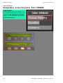
Diagnosis entry
Diagnosis input is entered via this function.
To start the function
click-select it.
The Diagnosis dialog
appears Ready for
your handling.
This is the diagnosis input area with its menu
pop-up key.
Here you may enter a
new diagnosis, its complete name and then
the abbreviation of it in
the pop-up field above.
Deletes selected Diagnosis name input.
Save to Exit
you to the patient archive
screen.
Clears all input in Diagnosis name area.
Cancels all diagnosis activity.
User Manual - FA092423 L - System FiVe - sw. 1.9.x
45
Chapter A - System Preparations
GE Vingmed Ultrasound
Image Recall
Recall the clipboard image
To recall Clipboard
stored images, press
this key. You are then
asked to click-select
one of the icons on the
clipboard area. Clickselect it.
Your selected image
recall is then displayed as shown
here.
46
User Manual - FA092423 L - System FiVe - sw. 1.9.x
GE Vingmed Ultrasound
Chapter A - System Preparations
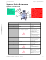
System Quick Reference
System connections
Note
Study mobility
warnings on
pageF-193 before
you start using the
systems mobility.
2
1
3
5
6
4
7
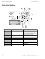
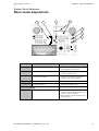
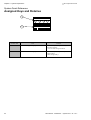
Number label
Title
Warning:
Even though they may look
and feel alright afterwards,
never continue using any
Vingmed Probes that have
been dropped onto or
bashed against hard surfaces . Such probes must be
disconnected and tested by
qualified personnel.
Contents
1
Headphone
- Headphone connector with volume control
2
Illum.
- One lamp connector with Intensity
adjustment
3
External I/O panel, (Left side, rear)
See warning text on pageF-193
- Two RS232 interface sockets
- One ECG TRIG socket
- One Ethernet interface socket
- One SVHS OUT socket
- One SVHS IN socket
- One Composite Video output
socket
- One Composite video input socket
- One B/W Video output socket
- Four Analog input sockets
- Output sockets for color printers
4
Patient I/O panel
- One pressure sockets(option)
- One Respiration socket(option)
- One Phono socket(option)
- One ECG socket
5
Rear wall
- One mains cable
- One Power ON/OFF switch
- Protective earth
6
Upper Front End panel
- Two Annular Phased Array probe
sockets
- One Doppler probe socket
- One system Standby-ON switch
7
Lower Front End panel
- Sockets for three Phased Array
probes
- A parking socket for an unused
Phased Array probe
P.S.A Phased Array probes must be
connected at position 1 before
Power Up.
User Manual - FA092423 L - System FiVe - sw. 1.9.x
47
GE Vingmed Ultrasound
Chapter A - System Preparations
System Quick Reference
System communication
1
3
4
2
5
7
6
Number label
48
Unit
Communication type
1
Screen
- Visual
2
Video Cassette Recorder
- Taped
3
Loudspeakers
- Sound
4
Control Panel
- Key
5
Printer
- Paper
6
Footswitch
- Pedal switches
7
Printer
- Paper
User Manual - FA092423 L - System FiVe - sw. 1.9.x
GE Vingmed Ultrasound
Chapter A - System Preparations
System Quick Reference
Screen areas
1
Patient
info
Clipboard
Scan
info
2
Number
label
Title
1
Information display area
2
Ultrasound display area
User Manual - FA092423 L - System FiVe - sw. 1.9.x
Contents
- Patient ID
- Clipboard
- Current clinical application icon
- Date and Time
- Operator ID
- Replay indicator
- Thermal index
- VCR Status
- Active mode
- Paddle report window
- System messages
- Warnings
- User adjustable parameters
- Performed measurements
- Measurements list
49
GE Vingmed Ultrasound
Chapter A - System Preparations
System Quick Reference
Scan mode selection
1
2
4
3
5
6
8
Number label
50
Title
7
Activity
1
ADD MODECURSOR/
- Adds a non-displayed mode to a Simplex
mode or Duplex mode situation in combination with the specific mode key
- Adds a screen cursor to desktop activities and
displayed communication windows
2
DOPPL.
- Starts the default Doppler Mode
3
M-MODE
- Starts the M-Mode
4
CW|PW
- Starts the CW and PW Doppler Modes
5
2D FREEZE
- Halts activity in 2D mode
6
CFM
- Adds Color Flow to 2D Mode and M-Mode
7
ACTIVE MODE
- Switches active mode in Duplex and Triplex
mode situations.
8
2D
- Starts the 2D mode
User Manual - FA092423 L - System FiVe - sw. 1.9.x
GE Vingmed Ultrasound
Chapter A - System Preparations
System Quick Reference
Basic mode adjustments
1
3
2
4
5
6
7
Number label
Title
Activity
1
TGC slides
- Adjust the amount of echo brightness at
specific depths in the 2D sector
2
GAIN, 2D
- Adjusts the overall amount of echo brightness within the 2D sector
3
GAIN, ACTIVE MODE
- Increases or decreases echo brightness
within the active mode window
4
Assigned keys and rotaries
- See next page.
5
ZOOM, Step variable.
- Enables step variable zoom.
6
7
Continuously variable ZOOM
Depth, 2D sector
User Manual - FA092423 L - System FiVe - sw. 1.9.x
- Enables continuously variable zoom.
- In 2D, 2D/color, M-Mode and Color MMode it adjusts the depth of the data sampling area which is displayed.
- In PW Doppler it adjusts the depth of the
measuring point.
51
GE Vingmed Ultrasound
Chapter A - System Preparations
System Quick Reference
Assigned Keys and Rotaries
1
2
52
Number label
Title
Contents
1
Upper assign panel
- A continually mode updated rotary function label window
- A row of mode assigned rotaries
2
Lower assign panel
- A continually mode updated key function
label window
- Mode assigned keys
User Manual - FA092423 L - System FiVe - sw. 1.9.x
GE Vingmed Ultrasound
Chapter A - System Preparations
System Quick Reference
System screen tools
1
Number label
2
Title
3
4
6
5
Activity
1
SPLIT SCREEN
- Divides the acquisition area into two halves,
horizontally or vertically.
2
SELECT SCREEN
- selects active screen
3
Select key
- confirms selections
4
Trackball
- steers the Pointing device
5
Vertical paddle switch
- moves activity between menu fields vertically.
6
Horizontal Paddle switch
- moves activity between menu fields horizontally.
User Manual - FA092423 L - System FiVe - sw. 1.9.x
53
GE Vingmed Ultrasound
Chapter A - System Preparations
System Quick Reference
Post-processing functions
1
2
3
4
5
6
7
8
9
10
11
16
Number label
54
15
14
Title
13
12
Activity
1
TEXT
- starts the text annotations function.
2
ARROW
- allows arrow annotation with trackball and
select key.
3
LINE ERASE
- removes a selected text line.
4
BODY MARK
- starts body marking function.
5
PAGE ERASE
- erases all annotation arrows on active screen.
6
REPORT
- starts the report generator function.
7
IMAGE RECALL
- recalls stored image from clipboard.
8
VIDEO PREVIEW
- displays video preview before VCR storage.
9
REC/PAUSE
- remote VCR control.
10
PRINT (ALT.)
- prints on alternative printer.
11
PRINT
- prints on default printer.
12
MEAS.
- starts M&A.
13
IMAGE SIZE
-changes size of displayed image .
14
FULL FREEZE
- halts active scanning
15
IMAGE STORE
- saves single images or cineloops to clipboard.
16
CALIPERS
- starts calipers M&A
User Manual - FA092423 L - System FiVe - sw. 1.9.x
Chapter B
Scanning
This section tells you about:
• 2D Mode . . . . . . . . . . . . . . . . . . . . . . . . . . . . . . . . . . . . . . . . . . . . . . . 56
• Depth Control . . . . . . . . . . . . . . . . . . . . . . . . . . . . . . . . . . . . . . . . . . . 64
• GAIN . . . . . . . . . . . . . . . . . . . . . . . . . . . . . . . . . . . . . . . . . . . . . . . . . . 65
• Acquisition mode handling . . . . . . . . . . . . . . . . . . . . . . . . . . . . . . . . . 67
• Memory Replay . . . . . . . . . . . . . . . . . . . . . . . . . . . . . . . . . . . . . . . . . . 69
• Annotations . . . . . . . . . . . . . . . . . . . . . . . . . . . . . . . . . . . . . . . . . . . . . 70
• Body Marks . . . . . . . . . . . . . . . . . . . . . . . . . . . . . . . . . . . . . . . . . . . . . 76
• Color Flow Mapping . . . . . . . . . . . . . . . . . . . . . . . . . . . . . . . . . . . . . . 81
• Traditional M-Mode . . . . . . . . . . . . . . . . . . . . . . . . . . . . . . . . . . . . . . . 97
• Anatomic M-Mode . . . . . . . . . . . . . . . . . . . . . . . . . . . . . . . . . . . . . . . . 100
• Color M-Mode . . . . . . . . . . . . . . . . . . . . . . . . . . . . . . . . . . . . . . . . . . . 104
• Side by side viewing . . . . . . . . . . . . . . . . . . . . . . . . . . . . . . . . . . . . . . 107
• Doppler . . . . . . . . . . . . . . . . . . . . . . . . . . . . . . . . . . . . . . . . . . . . . . . . 108
• Tape Recording . . . . . . . . . . . . . . . . . . . . . . . . . . . . . . . . . . . . . . . . . . 116
Chapter B -Scanning
GE Vingmed Ultrasound
2D Mode
Start 2D scanning
At every boot-up, the
System Five starts in
the previous shut-down
mode.Here, It is 2DMode.
About 2D Mode -1
2d mode gives a 2-Dimensional ultrasoundgenerated view of the
heart where you perfect
its presentation with
mode - available tools.
Place the probe onto
the patient, start scanning and image adjustment.
About 2D mode - 2
The gotten views allow you to study tissue behavior and valve functioning primarily.
In this case the patient
is also connected with
ECG cabling where
trace handling etc., is
described in chapter
A, under section for
Patient I/O & traces
setup.
56
User Manual - FA092423 L - System FiVe - sw. 1.9.x
GE Vingmed Ultrasound
Chapter B -Scanning
2D Mode
Ultrasound picture Controls
In 2d cardiac you may
have screen controls
situated shown on this
page. Which controls
are present and settings et cetera are definitively probe and
application selection
dependable.
The upper set of keyboard controls (4 ON/
OFF switches and 4
Rotaries) are here
available in live scanning. The Lower set (2
ON/OFF switches) is
available at FULL
FREEZE.
Tissue 2D
Tilt
DDP
Compress
Reject
Dynamic Range
To the left here we have two
screen paddle menu sets of 2D
cardiac picture controls. The
farthest away one is at FULL
FREEZE and the nearest in live
mode. None of these control
positions are permanent.
Contour
Diff off/on
Power
User Manual - FA092423 L - System FiVe - sw. 1.9.x
57
GE Vingmed Ultrasound
Chapter B -Scanning
2D Mode
Control Panel Re-programmable Rotaries & keys
Angle
Focus
Controls the scan sector angle.
Focus positions the transmit focus point(s)
within the transmitted sector depth, indicated by a focal marker on the screen depth
scale. Available focal regions overlap, and
make it possible to focus on any part of the
image.
If you use ZOOM in live 2D, the focal
point(s) move to within the zoomed part of
the image. If you exit from zooming, without touching the focal control, the focus returns to the position it had before you
activated ZOOM.
Frequency
Frequency is the transmitted frequency
that your acquisition scan has. Frequency variations, depends on probe and application selections.
-Increase the frequency value to improve resolution.
-Reduce thefrequency value to improve
penetration.
There is often a tradeoff situation between the two.
Frequency adjustment in 2D imaging
changes the display framerate and
moves the focal marker to a new position on the screen depth scale.
Cineloop (FULL FREEZE only)
is a group of functions that you to
create and run a mini movie from
the stack of scan data found in the
systems replay memory.
Framerate
Framerate controls the resolution in image movement and detail.
Increase the framerate to get frames with
less focal points and made up of wider
beams, which in turn gives images with
poor detail resolution but high temporal
resolution.
A framerate reduction does the exact opposite.
The control is not available for APAT
(annular array) probes.
Up/Down
Theseflip the ultrasound image upside
down or downside up.
Left/Right
These flip the ultrasound Image right or
left
B-Mode maps (Live and FREEZE)
This function Displays a menu of alternative color maps for displayed tissue, selectable from the trackball and Select key
area.
The Cineloop Re-programmables
58
User Manual - FA092423 L - System FiVe - sw. 1.9.x
GE Vingmed Ultrasound
Chapter B -Scanning
2D Mode
Screen commands, Cardiac, Live & Full freeze
DDP (Data Dependent Processing)
In cases where normal scan adjustments are not enough, cases
where random artifacts, appear as
bright speckles, in your image, try
DDP. Increase DDP to remove the
speckle without effecting moving
structures such as valve flaps etc.
Tissue 2D
Tilt
DDP
Compress
Reject
Dynamic Range
Compress
Compress adjusts the greyscale
range of your image. No Compress
hardens your image, giving it a
black and white appearance. Increased Compress tends to make
your image grayish, and in turn
softer.
Contour
Diff off/on
Power
Reject
Reject removes low amplitude unwanted noise echoes in
your image. Increased Reject darkens your image and removes more and more of the low amplitude echoes. Avoid
removing relevant low amplitude echoes. After Compress &
Reject, readjust Gain, if necessary.
User Manual - FA092423 L - System FiVe - sw. 1.9.x
U
D
R
Menu
L
Value
59
GE Vingmed Ultrasound
Chapter B -Scanning
2D Mode
Screen commands, Cardiac, live only
Dynamic range
Tissue 2D
This function gives shades of gray to the various intensities of
the incoming image data. It differs from Compress, Reject,
postprocessing or screen adjustment controls because it actually preprocesses the grayscale range of the incoming data.
Dynamic Range is a live mode function which is unavailable in
Full Freeze mode.
Tilt
DDP
Compress
Reject
Contour
Contour adjusts the edges enhancement in an image. Adjustments towards minimum give minimum enhancement.
Dynamic Range
Contour
Diff OFF/ON
This affects reverberations in the image. If turned on the frame
rate (or focal zones) will decrease, while the reverberations attenuate
Diff off/on
Power
Power
Power adjusts penetration effectiveness. It does not increase
the background noise that makes unwanted artifacts in doing
so. Power increase improves penetration.
60
User Manual - FA092423 L - System FiVe - sw. 1.9.x
GE Vingmed Ultrasound
Chapter B -Scanning
2D Mode
Sector Tilt
Tilt is active, whenever
there is a 2D image
present on the screen,
without a Time motion
cursor. When the cursor
is displayed, tilt adjustment is disabled.
The Yellow marker that is
visible at the top of the
sector, marks the probe
diode light’s position.
On this System a less
than 90°sector is tiltable
in any direction, left and
right, within the probes
90° scan range, by
merely stepping the
paddle.
Tissue 2D
Tilt
DDP
Compress
U
R
D
Menu
L
Value
Reject
Dynamic Range
Contour
Diff off/on
Power
User Manual - FA092423 L - System FiVe - sw. 1.9.x
61
Chapter B -Scanning
GE Vingmed Ultrasound
2D-Mode
Octave Tissue Imaging
Standard B-mode (2D) imaging transmits and receives ultrasound at roughly the same frequency. At higher power levels, return echoes from tissue are generated not only at the
original frequency but also at twice the frequency transmitted. This frequency, known as
the second harmonic, is one octave higher than the original frequency. These echoes are
mixed with normal echoes when they return to the transducere but are much weaker. Within the System Five the second harmonic, from the received spectrum is separated, amplified and processed for display.
To start Octave Tissue
Imaging that is available with 2.5 and
3.5MHz FPA, 3.25MHZ
Apa and 3.5MHz CLA
probes, adjust the Freq
rotary to the active
probe’s two lowest frequency levels.
A Text, confirming that
you are in Octave, appears in this information
window when it is active.
Shortly after the displayed image from Octave Tissue Imaging
appears.
Notice the displayed frequency
reading.
62
User Manual - FA092423 L - System FiVe - sw. 1.9.x
GE Vingmed Ultrasound
Chapter B -Scanning
2D-Mode
How does Octave Imaging improve image quality?
When Octave Imaging is active, the transmitted frequency is lowered, fully utilizing the high
bandwidth of the transducer. At lower frequency the ultrasound beam becomes less sensitive to the non-linear characteristics of tissue; it also penetrates further into the tissue before
losing signal strength.Thus with lower transmit frequency more signal energy reaches the
region of interest.
The harmonic ultrasound signal is then reflected from the organ and back to the transducer,
just like the original(fundamental frequency) ultrasound signal. Very little harmonic signal is
generated from “noise echoes” often seen in the blood pools and as general noise; therefore
the returned signal provides better contrast separation betweentissue and blood pools.
Since the frequency is doubled,Octave Tissue Imaging also provides twice the lateral resolution due to the increased effective aperture.
User Manual - FA092423 L - System FiVe - sw. 1.9.x
63
GE Vingmed Ultrasound
Chapter B -Scanning
Depth Control
Adjust Region of Interest DEPTH
2D Depth moves your
scanned Region of Interest, up or down, within the viewed sector.
It also redraws and
reduces Depth
reading here.
Move
ROI
Down
Move
ROI
UP
An example of
depth movement
could look like this.
The Region is now
at a lower position
on the screen.
64
User Manual - FA092423 L - System FiVe - sw. 1.9.x
GE Vingmed Ultrasound
Chapter B -Scanning
GAIN
Gain Location
To adjust the amplification of all received signals we have the Gain
center on the Control
panel. From it, you may
add and reduce the amplification over all, in the
active mode and at specific depths of received
scan data to improve the
detail visibility on the
screen.
User Manual - FA092423 L - System FiVe - sw. 1.9.x
65
Chapter B -Scanning
GE Vingmed Ultrasound
Gain
Adjust Gains
TGC has eight slide-potentiometers. Each of these allow you to
separately adjust the amplification
of displayed data at eight specific
depths on the displayed 2D sector.
The mid-positioning of all, shown
here should give correct TGC for
the normal patient.
Active Mode Gain adjusts, as it states, Gain in
the mode that is active. In
2D mode it does the same
as the 2D gain rotary. In
color flow it adjusts the
color flow etc.
2D Gain adjust the amplification of tissue in tissue in the
displayed 2D sector.
66
User Manual - FA092423 L - System FiVe - sw. 1.9.x
GE Vingmed Ultrasound
Chapter B -Scanning
Acquisition mode handling
Add modes
To add a mode to any
other mode, simply
press the other mode
directly. You can also
press the Add Mode/
cursor key, position the
cursor within the sector
at a suitable point for
proper M-Mode, and
then press the key for
the mode to be added
(the M-Mode key in this
example) thereby obtaining the duplex
mode.
User Manual - FA092423 L - System FiVe - sw. 1.9.x
67
GE Vingmed Ultrasound
Chapter B -Scanning
Acquisition mode handling
Use the Active Mode key to change Parameters
To display tissue adjustment parameters when
in 2D/Color Flow, with
Color Flow adjustment
parameters present,
press the Active mode
key once the Color flow
key starts to blink. Before it stops blinking
press the 2D key once.
The parameters appear
here.
The 2D tissue parameters are also available on the programmable rotaries as you can see in our example where
we have adjusted the Angle Rotary.
68
User Manual - FA092423 L - System FiVe - sw. 1.9.x
GE Vingmed Ultrasound
Chapter B -Scanning
Memory Replay
Replay memory handling
To do memory replay,
press FULL FREEZE at
a stage of interest in
your acquisition, and
your system memory
now filled with preliminary stored ultrasound
data.
So, as the system
prompts you to do, scroll
the Replay buffer with
the trackball.
Current frame.
Total number of
frames.
User Manual - FA092423 L - System FiVe - sw. 1.9.x
Number of seconds
from start of memory
69
Chapter B -Scanning
GE Vingmed Ultrasound
Annotations
Start Annotation
To start Annotations
on a displayed image,
select this key on the
control panel.
The light in the key lights
up and the Annotations
menu appears at this location on the screen.
Hint
When you select the TEXT key, you can start typing a text on the keyboard
that will appear on the sector without having done anything on the Annotations menu to begin with.
70
User Manual - FA092423 L - System FiVe - sw. 1.9.x
GE Vingmed Ultrasound
Chapter B -Scanning
Annotations
Add a menu Arrow
To add a menu arrow
select this menu position.
A quite different arrow pointer key is also available on the control panel. When
selected its key lights up and the arrow pointer pops onto the screen. It is also
maneuvered, positioned as if fastened to the trackball and select key.
An arrowhead appears
on the screen. Using the
trackball, maneuver it
onto the location you
want to anchor its shaft
at and press the select
key.
Using this knowledge, maneuver the shaft and
arrowhead so that it points at its target and
press select to anchor it completely.
User Manual - FA092423 L - System FiVe - sw. 1.9.x
Move the trackball
again and now the arrow shaft stretches, or
crimps or the whole arrow and shaft rotate
around the anchor.
71
GE Vingmed Ultrasound
Chapter B -Scanning
Annotations
Enter an menu text abbreviation
Highlight and choose
AO with the Select key,
and your input appears
with a text input cursor
behind it. If necessary,
you can edit or add text
from system keyboard.
Maneuver the input to
its planned position with
the trackball.
To anchor it at this location, press the select
key. Use Line Erase to
delete the selected input.
Use Edit to change a
text input or to move it
to another location.
72
User Manual - FA092423 L - System FiVe - sw. 1.9.x
GE Vingmed Ultrasound
Chapter B -Scanning
Annotations
Change a text entry
To Change a text entry,
choose Edit on the
menu, place the Cross
cursor that appears on
the screen, onto AO,
and press Select. A
short and vertical line
cursor, replaces the
cross, and places itself
behind the AO text.
Press the Backspace
key once, and O disappears.
You can also use the
LINE ERASE, and the
PAGE ERASE keys to
erase single entries,
one by one, or all entries in one selection.
User Manual - FA092423 L - System FiVe - sw. 1.9.x
73
GE Vingmed Ultrasound
Chapter B -Scanning
Annotations
Configuration
To do Annotations configuration click select
this position on the Annotations menu. A configuration dialog
appears.
Move Up or
Move Down
highlighted text.
Delete highlighted text.
Factory
Add new text entry input from
keyboard in this
area.
Cancel all configuration activities.
Save all changes, deletions, additions et cetera, and even establish a new menu position
if necessary after changes.
74
User Manual - FA092423 L - System FiVe - sw. 1.9.x
GE Vingmed Ultrasound
Chapter B -Scanning
Annotations
Setup
To do Annotation
settings select
the function here.
Do Annotations setup as
clearly explained on this
dialog.
User Manual - FA092423 L - System FiVe - sw. 1.9.x
75
GE Vingmed Ultrasound
Chapter B -Scanning
Body Marks
Start the Body mark function
To add BODY MARKS
to your displayed ultrasound picture, press
this key on the control
panel.
Page Erase removes all
Body marks and Annotation inputs. Line
Erase takes the click-selected ones only.
Body marks appear on the Annotations menu.
The body mark selection that appears is application-dependent. These are the Carotid application ones. See Body marks for other application
below. They function as described here.
Aorta IIiac
Pelvic and Gyn.
LegArt and
LegVein
Abdo,PedAbdo
and Renal.
Small Parts
76
User Manual - FA092423 L - System FiVe - sw. 1.9.x
GE Vingmed Ultrasound
Chapter B -Scanning
Body Mark
Select a body mark
Whenever you need to add a body mark during ultrasound scanning start the body marking function, decide which mark view suits your needs and click
select it shown below.
The Annotations
menu always appears in a ready for
editing status.
By default setup, the selected Body mark
pops onto your ultrasound situation,
shown here.The Probe Indicator is active
and locked to all Trackball movement,
ready to be moved around the Body
mark.
Key operators are:
Del to go Backwards one step, at
each entry, to previous activity.
Select to go forward one step to next
activity.
User Manual - FA092423 L - System FiVe - sw. 1.9.x
77
GE Vingmed Ultrasound
Chapter B -Scanning
Body Mark
Move the Body mark and Probe Indicator
To move the Body mark around
your ultrasound situation, press
the Del key and the Body Mark is
now locked to all trackball movement.
The Del key input exits you from
Probe Indicator movement to
Body mark movement.
Use the Trackball, move the
Body Mark to a desired position
on the ultrasound sector and
press Select to lock it there.
The Select input also exits you
from Body mark movement to
Probe Indicator movement.
To move the Probe indicator on the
Body mark, roll the Trackball in the
desired direction. When satisfactory,
press Select to lock it at the position.
The Select key input also exits you to
the next activity which is Turn or Rotate the Probe indicator at the
locked position. For more on this see
the next page.
A Del key input returns you to Move
Body mark mode, if you need to adjust it.
78
User Manual - FA092423 L - System FiVe - sw. 1.9.x
GE Vingmed Ultrasound
Chapter B -Scanning
Body Mark
Turn or Rotate Probe Indicator
The Indicator’s short and
right-angled line is the probe
head. The rest of it is the
probe body. Trackball rotation rotates the body around
the locked in place head.
Roll the Trackball to the left or
right and the Probe Indicator
turns or rotates leftward or
rightward.
At the new angle, press the
Select key once to lock it at this
position.
Select also exits you to the
next activity.
A Del input returns you to the
previous situation where you
can move the Probe Indicator
on the Body mark.
User Manual - FA092423 L - System FiVe - sw. 1.9.x
79
Chapter B -Scanning
GE Vingmed Ultrasound
Compound
Start Compound
Some probes for System
five have the Compound
function.
Traditional PV scanning
will normally give you a
screened image situation
similar to this.
Select the Compound
function here.
When activated Compound gives you a
screen situation that resembles this. You
should clearly see that
the area within the yellow rectangle is much
clearer than in the image above.
The reason for this is
that with Compound
one scan is “shot” within the dot- rimmed area
and the next one within
the Line-rimmed area.
This gives the Yellow
marked area double
coverage which results
in a better picture.
80
User Manual - FA092423 L - System FiVe - sw. 1.9.x
GE Vingmed Ultrasound
Chapter B -Scanning
Color Flow Mapping
Start Color Flow in 2D mode
To start Color Flow in
2D mode, press this key
directly or go via the
Add Mode/Cursor key.
Two clearly seen lines
appear on the 2D sector that mark the color
limits.
As you scan in live
mode you will see color flow appear within
this sector. You may
need to adjust the Active Mode gain rotary.
Note that the term Color Flow is a generic term which includes the three Color Flow
modes that are available in the system:
* Conventional Color Flow Mapping
* Power Amplitude Doppler (Ref: page 96.)
* Tissue Velocity Imaging (optional).See separate Manual.
Conventional Color Flow Mapping provides information (bandwidth and direction)
about the velocity, bandwidth and direction of blood flowing in the Region of Interest
box. Blood flowing towards the transducer is mapped in red, while blood flowing away
from the transducer is mapped in blue. Blood flow that contains a variety of velocities
which often appear where there is turbulence or a jet mapped in green.Tissue Velocity
Imaging maps velocities from tissue motion to colors in accordance with a color map.
User Manual - FA092423 L - System FiVe - sw. 1.9.x
81
GE Vingmed Ultrasound
Chapter B -Scanning
Color Flow Mapping
Move the color sector within the 2D sector
In live scanning, right
and left Trackball movement moves the color
sector simultaneously.
You may also want to
change color maps and
this is done at the assignable keys on the
control panel.
82
User Manual - FA092423 L - System FiVe - sw. 1.9.x
GE Vingmed Ultrasound
Chapter B -Scanning
Color Flow Mapping
Programmable Keys and Rotaries
Here are the re-programmable keys and
Rotaries in live color
flow.
The same in FULL
FREEZE.
Low Velocity Reject removes all low velocity
signals below certain
predefined levels.
These are normally
coming from low velocity blood flow and tissue
movement noise.The
rotary has two steps, or
levels. Find the current
level at this position on
the Tissue/Color Flow
Mapping settings information window.
WARNING
Frequency adjustment In Doppler or Color
Flow modes affects the maximum size of the
available velocity range. (Frequency increase
lowers the maximum).
User Manual - FA092423 L - System FiVe - sw. 1.9.x
83
Chapter B -Scanning
GE Vingmed Ultrasound
Color Flow Mapping
Color map selection
To change color maps
press the below shown
programmable key
marked COLOR MAPS.
On the Color Menu use
the trackball and select
area key to choose your
map selection.
84
User Manual - FA092423 L - System FiVe - sw. 1.9.x
GE Vingmed Ultrasound
Chapter B -Scanning
Color Flow Mapping
Invert color map
To Invert your color
map, press this key.
The inverted map appears here.
User Manual - FA092423 L - System FiVe - sw. 1.9.x
85
Chapter B -Scanning
GE Vingmed Ultrasound
Color Flow Mapping
Region of interest handling
Adjust ROI Span shown above to
achieve situations to the right and
adjust ROI Width shown below to
the Right, to achieve situations
shown direct below. Trackball adjusts the angle of ROI.
86
User Manual - FA092423 L - System FiVe - sw. 1.9.x
GE Vingmed Ultrasound
Chapter B -Scanning
Color Flow Mapping
Tissue priority
While you are scanning
or in FULL FREEZE
Move onto Tissue Priority on the paddle menu
and pace it at a minimum value with the
right/left paddle. The
color on your image has
now the priority shown
to the right. You may
here have tissue detail
that is not visible because of flow. Continue
with the investigation
shown below.
Hint
The paddles govern the right hand
menu as described earlier.
Using the same paddle
and in live or frozen status and adjust Tissue
priority to the approximately same level
shown to the left. Color
is hardly visible, and tissue has the priority. It is
now possible to view
structures that were not
visible when color had
the priority.
User Manual - FA092423 L - System FiVe - sw. 1.9.x
87
Chapter B -Scanning
GE Vingmed Ultrasound
Color Flow Mapping
Baseline
In color flow, find Baseline on the re-programmable rotaries shown
below and on the paddle menu. It allows you
to view suspecting flow
velocities shown in examples to the right and
below.
Above we adjust
Baseline to a minimum, to study the
negative velocities.
Notice the color bar.
To the left we adjust
Baseline towards
maximum to look at
positive velocities.
Notice also the color
bar change and variance is present in
both.
88
User Manual - FA092423 L - System FiVe - sw. 1.9.x
GE Vingmed Ultrasound
Chapter B -Scanning
Color Flow Mapping
Variance
At a minimum setting
or, when switched off
at the re-programmables the Variance function is not present on
the color bar or in the
displayed flow of the
right hand view.
About Variance - 1
Variance selection, is available in both live scanning and
full freeze
Variance is a measure of how
disturbed, or non-luminary
the flow is at the given sample volume. From a technical
point of view, it is the bandwidth of the velocity information.
Whereas when you
paddle onto or switch
On Variance it is
present on the image
and in the color bar.
About Variance - 2
Use Variance maps when
you look at disturbed flows.
Such flows include jets of all
sorts, regurgitations, leaks,
ASDs, VSDs and the like.
Intensity is a measure of the
amplitude of the echoes
coming back from the sample volume. Intensity maps
are best suited when you are
looking at slower flows, ventricle filling, Carotids etc.
User Manual - FA092423 L - System FiVe - sw. 1.9.x
89
GE Vingmed Ultrasound
Chapter B -Scanning
Color Flow Mapping
How Color Flow Mapping works
Understanding the basic processes for Color Flow images is how to get the best color
flow images possible from striking the optimal balance between frame rate, mapping
angle, quality (“packet size”) and Low Velocity Reject.
This section will establish a basic understanding of what color flow mapping is, and
briefly describe the complex series of events that must happen to build a color flow map
in real time.
In Doppler Spectrum Analysis (pulsed) a large mathematically transformed data set
from a given sample volume is to yield the spectrum of velocities present in that sample
volume over the time. Because the interrogation of one specific sample volume at a time
is typical, there is a continuous stream of data available from that location, and time or
frame rate is not a factor.
In Color Flow Mapping, a limited set of data from a given sample volume is collected
over an interval of time which is as short as possible. Mathematically manipulated data
produce the Color Flow outputs for this sample volume. The outputs obtained are an
estimate of the mean velocity, the intensity or power of the signal, and a measure of the
statistical variance of the velocities in the sample.
90
User Manual - FA092423 L - System FiVe - sw. 1.9.x
GE Vingmed Ultrasound
Chapter B -Scanning
Color Flow Mapping
Color Map construction
A color flow map construction enhanced from an array of a variable amount of independent color flow lines, each of which is taken from a variable amount of independent sample volumes, obtained as described on the previous page. Although all the sample
volumes on a given flow line are evaluated and obtained simultaneously, each line requires many ultrasound pulses to make velocity estimates.
The flow information from the array of lines combined with 2D information, collected on
an independent 2D scan, to yield the whole color flow map. At each location in the displayed sector you have either an echo intensity or a mean velocity.Constructing a color
flow image, therefore, can take a considerable length of time.
The key to understanding the velocities being mapped
is understanding the color bar. This is a pictorial translation table that will allow you to associate a color on
the flow map with a particular flow state. To understand
what the color bar represents, one must first understand what information is available from the color flow
mapping process.
User Manual - FA092423 L - System FiVe - sw. 1.9.x
91
GE Vingmed Ultrasound
Chapter B -Scanning
Color Flow Mapping
The Spectral Estimate
Spectral estimation is the process in which the CFM extracts velocity information from
the returning Doppler shifted ultrasound data. Thethree parameters, mean velocity, signal intensity, and the variance of velocity determines each pixel on the flow map, i.e.,
each range gate along each flow vector. The mean velocity is the statistically determined average velocity. Variance is a measure of the bandwidth of the velocity spectrum. It tells how much the velocity typically deviates from the average velocity. The
intensity is a measure of the returning signal strength.
Spectral estimation depends on a mathematical process called auto-correlation to convert the Doppler shifted echoes into velocity information. The raw outputs of the autocorrelation process are a set of rays, each having an angle and a length. The angle of
the ray corresponds to the velocity, and can range from O to 1 Nyquist Velocity covering
the span of O to 180°. The length of the ray is proportional to the signal intensity.
Spectral estimate rays can be drawn on the wheel shown here. On this wheel one ray
is drawn, although for the spectral estimate there will be at least three (Application dependent) generated in the Color Flow Mode. One thing to notice is that for any given ray
there is no way to deduce whether the velocity detected is flowing to or from the transducer. Inference from observed hemodynamics, determine the flow direction in clinical
situations.
Increasing “red” velocities
Nyquist
velocity
Zero
velocity
Increasing “blue” velocities
92
User Manual - FA092423 L - System FiVe - sw. 1.9.x
GE Vingmed Ultrasound
Chapter B -Scanning
Color Flow Mapping
Assigning Colors and unwrapping the Color Wheel
Locations on the wheel shown on the previous page have assigned colors in red/blue
flow maps. This type of color assignment is the core of most manufacturer’s red/blue
maps. In the Vingmed map, intensity is an additional factor. This will appear on the color
wheel as concentric rings, growing brighter as the diameter grows. Adding intensity to
the color assignments helps to give the mapped velocities a more flow-like appearance.
Although the flow wheel represents a continuous process, in color flow mapping systems
the wheel is always “cut” at some point to be unwrapped and displayed on the monitor.
The exact cut location on the wheel is arbitrary. The cut location is similar to the position
of the baseline in a Doppler spectrum display.
User Manual - FA092423 L - System FiVe - sw. 1.9.x
93
GE Vingmed Ultrasound
Chapter B -Scanning
Color Flow Mapping
Disturbed Flow Indicator
The Disturbed Flow Indicators purpose is to help in
the visualization and delineation of turbulent flows
and jets. A set of color maps is available for selection
on the Color Map menu. In cardiac Yellow/Cyan is
the normally used map. Disturbed Flow describes a
variety of flow conditions that are not well defined by
a flow map that incorporates only the velocity and intensity parameters into the color assignment process.
The turbulence causes the presence of a broad
range of velocities so that the mean velocity statistic
is not very significant. This is the classic example of
Disturbed Flow. The variance display allows you to
see variation from normal velocities or turbulent flow.
This type of turbulent flow ids associated with doppler data with a broad bandwidth such as signals
generated by valvular regurgitation, valvular stenosis and intercavity shunts.
With the Disturbed Flow Indicator system, when the
system determines that the given combination of intensity, mean velocity and variance will not yield
meaningful mean velocity data, a shade of green
substitution, not addition, forthe mean velocity color.
These green areas stand out from the other flow areas, and catch the eye’s attention as often brief phenomena pass by. The heart of the Disturbed Flow
system is Deciding exactly when to substituted
mean velocity for the Disturbed Flow green. This is
what provides the outstanding jet and turbulent flow
visualization in the CFM.
94
Yellow
Green
Nyquist
Cyan
Variance
User Manual - FA092423 L - System FiVe - sw. 1.9.x
GE Vingmed Ultrasound
Chapter B -Scanning
Angio
Start Angio
Get a good tissue view
of the object of interest.
Add color flow mode.
Press this key to start Angio.
Maneuver the color
sector slowly and you
can see the low flow of
your area of interest.
See also the change in
the Color Bar.
User Manual - FA092423 L - System FiVe - sw. 1.9.x
95
GE Vingmed Ultrasound
Chapter B -Scanning
Angio
Power amplitude Doppler, Angio
Note that the term Color Flow is a generic term which includes the three Color Flow
modes that are available in the system:
* Conventional Color Flow Mapping (Ref: page 81.)
* Power Amplitude Doppler
* Tissue Velocity Imaging (optional). See separate Manual.
Power Amplitude Doppler, also known as Ultrasound Angio or Doppler Energy, uses
the same data as acquired using Conventional Color Flow Mapping. In Power Amplitude Doppler it is the of the doppler signal amplitude that represents the intensity which
is mapped to a color instead of the velocity, bandwidth and direction. Undesired signals
from slowly moving tissue structures are surpressed by the same type of wall filter.
Power Amplitude Doppler provides noticeably higher sensitivity because of much lower
pulse repetition frequency and extensive temporal processing.
Tissue Velocity Imaging maps velocities from tissue motion to colors in accordance
with a color map.
96
User Manual - FA092423 L - System FiVe - sw. 1.9.x
GE Vingmed Ultrasound
Chapter B -Scanning
Traditional M-Mode
Start M-Mode, duplex view
In 2D mode, press the
ADD CURSOR/MODE
key and position the
cursor line on a tissue
area of interest. Press
this key to start 2D/MMode.
Shortly after, Duplex
M-Mode replaces 2D.
About M-Mode
In Traditional M-Mode,
Tissue Data is continually gathered along the cursor line on the 2D image.
Each recorded pulse is
joined together and presented horizontally within
a rectangle which has a
horizontal time scale and
a vertical depth scale. It
is normally used to scrutinize found tissue abnormalities on the 2D image.
User Manual - FA092423 L - System FiVe - sw. 1.9.x
97
GE Vingmed Ultrasound
Chapter B -Scanning
Traditional M-Mode
Elements in duplex M-Mode display
The cursor line on the
2D image is repositioned with the trackball, if necessary.
Time scale.
Horizontal Sweep
regulates the update
rate of screen-displayed M-mode.
Moving Erase bar is
present while updating MMode in live mode.
The Depth scales
aid you in pinpointing occurrences of
interest in the presented situation.
The controls available
for M-Mode perfection
are the same as for 2D,
apart from Horizontal
sweep, which is described here.
98
User Manual - FA092423 L - System FiVe - sw. 1.9.x
GE Vingmed Ultrasound
Chapter B -Scanning
Traditional M-Mode
Image size
Press this key to toggle between small or
larger 2D image, depending on which
size is displayed by
default setting as described in Chapter A.
User Manual - FA092423 L - System FiVe - sw. 1.9.x
99
Chapter B -Scanning
GE Vingmed Ultrasound
Anatomic M-Mode
Prepare for Anatomic M-Mode
In 2D, as shown here,
press Full Freeze and
the M-MODE key directly after to obtain Anatomic M-Mode.
Scroll through and study data
from the Replay Buffer, using the
trackball.
100
User Manual - FA092423 L - System FiVe - sw. 1.9.x
GE Vingmed Ultrasound
Chapter B -Scanning
Anatomic M-Mode
Maneuvering the cursor line
Still in full freeze status,
press ADD CURSOR/
MODE once to move
activity to the 2D image
and thereby access to
cursor line maneuver.
The Instruction Move Cursor
is displayed at the left side of
the lower edge of the screen.
Using the trackball, maneuver the line cursor,
and position its sampling markers on an
area of interest.
When you stop maneuvering these a display
update of the M-Mode
view at the new location
of interest occurs.
Press ADD CURSOR/
MODE once more to return to normal M-Mode
Replay buffer scrolling.
User Manual - FA092423 L - System FiVe - sw. 1.9.x
101
Chapter B -Scanning
GE Vingmed Ultrasound
Anatomic M-Mode
Anatomic M-Mode viewing
After positioning the cursor and Sampling markers, press the Select
area, surrounding the
trackball, once to toggle
from Move Cursor activity to Turn AMM Cursor.
At the new cursor position, maneuver the
trackball, a new cursor
line, that is anchored at
the old cursors sampling marker, appears.
Hint
Anatomic M-mode can be
initiated in both 2D Tissue
and 2D Color Flow modes.
As you move the
trackball, it rotates
freely in the direction of the movement. When you
stop, an M-Mode
redo at the new location occurs. At
this stage do a survey of the area in
Anatomic M-Mode.
102
User Manual - FA092423 L - System FiVe - sw. 1.9.x
GE Vingmed Ultrasound
Chapter B -Scanning
Anatomic M-Mode
About…
Anatomical M-Mode is a most useful tool for the validation and quantification of tissue
movement and thickening. It is for instance possible to measure wall thickening in locations where the wall boundary is parallel with the acoustic beams. The anatomical
M-Mode applied to tissue velocity data provides the tool that resolves the complex
motion characteristics of myocardial wall movement. The Anatomical M-Mode lines
are sampled with the same temporal and spatial resolution as done with the 2D tissue or 2D color flow images, making it possible to produce high quality M-Mode images from high framerate 2D acquisitions.
User Manual - FA092423 L - System FiVe - sw. 1.9.x
103
Chapter B -Scanning
GE Vingmed Ultrasound
Color M-Mode
Select Color M-Mode
In 2D/M-Mode, press
this key, to select Color
M-Mode, and below
shown color information, representing
speed (movement), appears.
104
User Manual - FA092423 L - System FiVe - sw. 1.9.x
GE Vingmed Ultrasound
Chapter B -Scanning
Color M-Mode
Assignables, screen functions, live
Sample Volume determines
the size of the flow data gathering area.
Radial averaging is vertical
data averaging to get
smoother M-Mode flow.
ColorMMode
Tissue Priority
Sample Volume
Baseline
Frequency
Radial Avg.
Power
WARNING
Frequency adjustment In Doppler or Color Flow modes affects the maximum size
of the available velocity range. (Frequency increase lowers the maximum.
User Manual - FA092423 L - System FiVe - sw. 1.9.x
Information
Find missing Color M-Mode
commands and adjustment descriptions in 2D, M-Mode and
Color flow descriptions.
105
GE Vingmed Ultrasound
Chapter B -Scanning
Color M-Mode
Assignables, screen functions, FULL FREEZE
Information
Find missing Color M-Mode commands and adjustment descriptions in 2D, M-Mode and Color
flow descriptions.
106
User Manual - FA092423 L - System FiVe - sw. 1.9.x
GE Vingmed Ultrasound
Chapter B -Scanning
Side by side viewing
Choose side by side view
The default setting on
the screen configuration menu, over/under,
is the automatic choice
when selecting duplex
modes.
To present the new
view, shown to the left,
press the SELECT
SCREEN key.
Repeat the above to
return the default view.
User Manual - FA092423 L - System FiVe - sw. 1.9.x
107
Chapter B -Scanning
GE Vingmed Ultrasound
Doppler
Start PW Doppler Mode
From 2D mode, press
this key to add Doppler
from the region of interest marked by the TM
cursor. The 2D picture
is rescaled, and the
Doppler Window appears below it.
108
User Manual - FA092423 L - System FiVe - sw. 1.9.x
GE Vingmed Ultrasound
Chapter B -Scanning
Doppler
Start Duplex CW Doppler
Press this key to start
live Duplex CW Doppler shown below.
Depth scale in mm.
The 2D situation with
continually adjustable TM cursor and a
depth scale.
A velocity scale in
m/s, (meters per second).
A Doppler center
Baseline.
A time scale in seconds.
The ECG trace rescaled to fit the Doppler window.
User Manual - FA092423 L - System FiVe - sw. 1.9.x
109
GE Vingmed Ultrasound
Chapter B -Scanning
Doppler
Carotid Angle Correction
Obtain a good image
and engage the Cursor
with the Add Mode/
Cursor key.
Move the Cursor with
the Trackball and place
the Angle Correction
marker, on the cursor
sample volume, in the
center of vessel.
Press the Select key
once, adjust the angle
until the yellow line is
parallel with the vessel
wall or the assumed direction of flow.
Press one of the Doppler
Mode keys and continue
the investigation.
110
To move the cursor to another position press the
Select key once more.
User Manual - FA092423 L - System FiVe - sw. 1.9.x
GE Vingmed Ultrasound
Chapter B -Scanning
Doppler
Peak Velocity Correction
Peak velocity Correction is used
for finding a more correct maximum velocity reading as a function of Tilt Angle Correction,
Sample Volume and Depth.
With the above situation the
Automatic Peak Velocity Correction is switched ON/OFF
here.
When switched ON the Velocity is corrected and the Doppler
scale is Green.
User Manual - FA092423 L - System FiVe - sw. 1.9.x
111
GE Vingmed Ultrasound
Chapter B -Scanning
Doppler
Sample Volume size change
Sample Volume Controls size of the doppler
Sample Volume (Gate).
The horizontal paddle
adjusts the Sample Volume. The vertical paddle finds the Sample
Volume
Increasing the sample volume size improves sensitivity
but reduces spatial
resolution.
112
This also reduces
the achievable
maximum velocity
range.
User Manual - FA092423 L - System FiVe - sw. 1.9.x
GE Vingmed Ultrasound
Chapter B -Scanning
Doppler
Assignables, screen commands, live
Doppler PW
Sample Volume
Compress
Reject
Frequency
Framerate
Tracking
Overrange
Power
Angle Corr.
Baseline
Controls position of the zero velocity baseline of the
spectral display. To be used to help avoid aliasing of
the doppler display.
Doppler CW
Compress
Reject
Frequency
Framerate
Power
Angle Corr.
WARNING
Frequency adjustment In Doppler or
Color Flow modes affect the maximum
size of the available velocity range.
Frequency increase lowers the
maximum.
User Manual - FA092423 L - System FiVe - sw. 1.9.x
113
Chapter B -Scanning
GE Vingmed Ultrasound
Doppler
Doppler Control descriptions
Velocity Range
Control the velocity range of the spectrum display.The requested velocity range will not
necessarily be achievable. The available range depends on parameters like frequency,
sample volume position and sample volume size. If the required range is not achievable
reducing the sample volume size might help.When measuring high velocities one might
get unlikely sample volumes. To get rid of these use either the LPRF control (this will lower
the velocity range) or the Overrange control. The displayed velocity range depends on the
setting of the Angle Correction.
Tracking
Controls the spectral analyzers “tracking” of blood cells. When tracking is off (set to minimum value) the analyzer will work in the traditional way. Increasing the tracking will make
the analyzer to try to “track” the blood cells. This will improve the resolution of the spectral
display, and it makes it possible to measure velocity above the Nyquist velocity. But increasing the tracking will also reduce the sensitivity of the doppler. See also Overrange
control.
Overrange
If overrange is on (value higher than minimum) the spectral analyzer analyzes velocities
beyond the Nyquist velocity. This will make the measurement of high velocities possible
without the drawback of unlikely sample volumes. To make it possible to distinguish the
signal from blood moving with velocities beyond Nyquist velocities from ghosts from lower
velocity signals tracking must be on (see Tracking control).
114
User Manual - FA092423 L - System FiVe - sw. 1.9.x
GE Vingmed Ultrasound
Chapter B -Scanning
Doppler
Assignables, screen commands, FULL FREEZE
Find information from the
Doppler scanning at this
location on the screen.
User Manual - FA092423 L - System FiVe - sw. 1.9.x
115
GE Vingmed Ultrasound
Chapter B -Scanning
Tape Recording
Control Panel VCR controls
Press this key to Record screen
activities.
Press this key to Pause recording
screen activities.
Press this key to Initiate Video Playback.
A set of VCR functions appear at the switches and rotaries.
These include Shuttle
speed for manual adjustment of video playback speed.
Stop to halt video
playback.When stop
has been activiated,
the LCD shows Eject
FF to move video
playback Fast forward.
Press REW to rewind
played VCR tape.
116
Press this key to play and
display on screen the recorded screen activities.
User Manual - FA092423 L - System FiVe - sw. 1.9.x
Chapter C
Applications
This section tells you about:
• User Defaults storage . . . . . . . . . . . . . . . . . . . . . . . . . . . . . . . . . . . . . 118
• System Five, SuperVision . . . . . . . . . . . . . . . . . . . . . . . . . . . . . . . . . . 120
• Biopsy Option . . . . . . . . . . . . . . . . . . . . . . . . . . . . . . . . . . . . . . . . . . . 126
GE Vingmed Ultrasound
Chapter C - Application
User Defaults storage
User Defaults selection
This function allows you
to save and recall system
adjustments and setups
to add effectivity to your
acquisition routines. How
to do this follows.
Select the Probe, Scan
the patient and adjust
the system to optimize
the scan.
To gain access to the Applications menu,
press the APPLICATION key.
To open the User Defaults setup dialog, clickselect User Defaults on
the displayed Applications Menu.
Here, you can Save settings under a filename, Set as Default for present acquisition, Deleted altogether or you can use
FACTORY set instead.
IMPORTANT
Your POWER control setting is not stored with
your saved user default.
118
User Manual - FA092423 L - System FiVe - sw. 1.9.x
GE Vingmed Ultrasound
Chapter C - Application
User Defaults Storage
Save and Recall your user default
Type your User Defaults
identity as shown here
and place the cursor
onto Save and click it.
Your entered setup filename appears on the
list below the naming
window.
To recall your default setup, which in our example
was in Cardiac acquisition you can find your
saved defaults file on the
Settings Menu that appears when you highlight
Cardiac shown here. Otherwise, you must find it
via the User Defaults
menu.
Note
If you have chosen your own setting its filename
appears on the scanner info window, under the
chosen application.
User Manual - FA092423 L - System FiVe - sw. 1.9.x
To return to the Users
Defaults menu and click
Set as Default which will
make this setting the
automatic choice the
next time you choose
Cardiac on the Application Menu.
119
GE Vingmed Ultrasound
Chapter C - Application
System Five, SuperVision
Handle EchoPAC on System FiVe
Some System Fives are shipped with an EchoPAC integration. These have
added functionality within and SuperVision added to their product names.
The following section describes how the integration affects normal System
Five use. The EchoPAC integration boots at system boot-up.
Whenever you need to switch from
System Five scanning and over to
the EchoPAC program, press this
key.
After selection, EchoPAC display covers this
area.
The Trackball and Select
area function as your
stand-alone mouse, and
it’s Select key when
EchoPAC is active.
This keyboard covers
most of your normal
EchoPAC needs but
some shortcuts may fail.
This miniature monitor,
found just above the keyboard, continuously displays the current
EchoPAC situation.
120
User Manual - FA092423 L - System FiVe - sw. 1.9.x
GE Vingmed Ultrasound
Chapter C - Application
System Five, SuperVision
Patient ID entry selection
To do Patient ID entry on System
FiVE with EchoPAC active, press
this key.
This executes an automatic
switch to the EchoPAC patient
handling functions.
Here, you can choose
this function to fulfill
your ID entry task.
Find descriptions of
the other functions
here, in the EchoPAC
User Manual.
Hint:
To Eject Magneto Optical
Disks from System FiVe
press fn and e keys once.
User Manual - FA092423 L - System FiVe - sw. 1.9.x
121
Chapter C - Application
GE Vingmed Ultrasound
System Five, SuperVision
Patient ID input
Do patient ID input as
described in the EchoPAC User Manual*.
After ID entry, you exit
from it, and the Home
screen appears on the
screen showing your entered ID.
Shortly after the System FiVe scan situation appears showing
the automatically entered ID at this location.
*Note:
Please refer to these
EchoPAC User manual
Part Numbers:
EP192010_D for 6.3.x sw
ML292397_E for 5.4.x sw
ML292223_I for 5.4.x sw
122
User Manual - FA092423 L - System FiVe - sw. 1.9.x
GE Vingmed Ultrasound
Chapter C - Application
System Five, SuperVision
Special Setup functions
Switch EchoPAC Video
Grabbing ON when you
want to do video grabbing from the System
Five video signal and
transfer it to EchoPAC.
The Transfer in detail is
also dependent on other setups on this menu.
In live mode you get a
raw data transfer of the
scan activity on the
screen.
At full freeze you transfer the amount of rawdata memorized by the System FiVe, or a normal
copy of the present screen picture or a high
resolution copy of the screen picture.
Select these to make
the Footswitch work in
EchoPAC only. Then the
footswitch acts as it
does on the EchoPAC
stand-alone. See the
EchoPAC User Manual
for details.
User Manual - FA092423 L - System FiVe - sw. 1.9.x
123
Chapter C - Application
GE Vingmed Ultrasound
System Five, SuperVision
Footswitch activity messages
When doing Continuous
capture, from System
FiVe to EchoPAC, display
of the footswitch activity
Status messages, for
Grabbing and Pause appear at this location.
124
User Manual - FA092423 L - System FiVe - sw. 1.9.x
GE Vingmed Ultrasound
Chapter C - Application
System FiVe SuperVision
Willful System shut-Down with integrated Mac™
During normal everyday conditions, always use following shut-down routine:
-Set in standby-mode with Standby/ON key.
-Allow time for computer to clear up and organize it’s data and allow
the system to come to rest in Stand-by mode.
-After this, switch power off with the Power ON/OFFswitch at the system rear.
User Manual - FA092423 L - System FiVe - sw. 1.9.x
125
GE Vingmed Ultrasound
Chapter C - Application
Biopsy Option
Introduction
Intended use
The biopsy option is intended for use by a duly licensed physician who has received the
appropriate training in biopsy techniques as dictated by current relevant practices, as
well as in proper operation of the System FiVe Ultrasound Scanner.
This device provides a mechanical means for doing needle / instrument guided procedures with the use of a diagnostic ultrasound probe. A reusable bracket is securely positioned over the probe body allowing attachment and use of disposable needle guides.
This device provides a fixed path for the needle or instrument that, when coupled by the
ultrasound system software, corresponds to on-screen imaging guidelines for visualizing
guided instrument placement procedures. Furnish the CIVCO Biopsy Needle Guide includes transducer cover, which are disposable for single patient / procedure use, sterile.
The single use, disposable feature helps to prevent transfer of microorganisms, body fluids, and particulate material to the patient and health care worker during reuse of the
transducer. Furnish the reusable Biopsy bracket non-sterile, and clean it before each use
to the user-required disinfection level.
A Biopsy Bracket
A Probe.
A Needle Guide with reversible snap-on, snap-off, holechannel piece.
A Biopsy Needle with protection sheath.
Sterile GEL sachet and
Sterile Cover.
Sterile Kit packaging.
Rubber Bands.
126
User Manual - FA092423 L - System FiVe - sw. 1.9.x
GE Vingmed Ultrasound
Chapter C - Application
Biopsy option
Bracket and Needle guide mounting (10MHz FLA-Feb.99)
Mount the Bracket on the probe.
Slide the
fastener in
place as
shown here.
Tighten the
fastener as
shown here.
Add GEL to the
probe scan face.
Caution
Follow the texts on the
right hand side step by
step from top to bottom
Gently snap the Needle
Guide onto the Biopsy
Bracket as shown here.
Drape the probewith bracket tightly using the sterile cover from the Biopsy kit.
Remove any air bubbles that are trapped between the sterile cover and the gel, before
sealing the cover’s open end with sterile rubber bands from the kit.
WARNING
Avoid puncturing the sterile cover.
WARNING
Use the utmost of care when you are
mounting and dismounting the Bracket.
Add some sterile Gel,
from the Biopsy kit, to
this area of the cover.
User Manual - FA092423 L - System FiVe - sw. 1.9.x
127
Chapter C - Application
GE Vingmed Ultrasound
Biopsy option
Bracket and Needle Guide mounting (3.5MHz CLA)
Mount the bracket onto
this side of the probe so
that the three protrusions on the inner side
of the bracket rest in the
three square groves on
the probes housing. It is
necessary to loosen the
bracket fastener before
the mounting and to
fastening it again afterwards.
With sterile precautions,
drape this probe and
bracket as described on
the previous page.
WARNING
Avoid puncturing the sterile
cover.
Gently snap the Needle Guide onto the
Biopsy Bracket as
shown here.
WARNING
Avoid compromising sterile
parts.
128
User Manual - FA092423 L - System FiVe - sw. 1.9.x
GE Vingmed Ultrasound
Chapter C - Application
Biopsy option
Start the Biopsy Option
To start the Biopsy Option,
press this key on the Control
Panel.
A Biopsy menu appears on the screen. It consists of click-selectable keys for Probe type/Needle thickness selection.
Choose a needle with an appropriate gauge (14,
16, 18, 20 or 22) for the job.
Press the appropriate needle key as input for the
system.
The Biopsy guide lines
replace the menu on
the screen’s ultrasound area. (1.0cm
between large yellow
dots, 0.5cm from large
yellow dots to small
yellow dots and 5.0cm
between red dots).
User Manual - FA092423 L - System FiVe - sw. 1.9.x
129
GE Vingmed Ultrasound
Chapter C - Application
Biopsy option
Determine Biopsy needle length
To determine the needed
needle length, scan and
find the best possible passageway to the area of interest. When you find it,
press Meas, the scanning
halts and you can retrieve
the situation from the Replay memory.
Choose Biopsy Cal on
this appearing menu.
On the the displayed Measurements menu, a measurement
start point setting appears at a
point where upward extended
guide lines cross the leftward extended 0 depth line of the scan.
Roll the trackball diagonally downwards to
the right and the green
cursor appears.
Maneuver it until it
reaches the point of interest. Press Select to
mark the end point of
the measurement.
Two measured distances appear here. These
are; Dist which is the
distance between the
point of interest and the
0 depth mark, and Needle which is distance
between the top of the
needle guide and the
point of interest.
130
User Manual - FA092423 L - System FiVe - sw. 1.9.x
Chapter D
Using M&A
This section tells you how to:
• M&A examples . . . . . . . . . . . . . . . . . . . . . . . . . . . . . . . . . . . . . 132
• M-Mode M&A . . . . . . . . . . . . . . . . . . . . . . . . . . . . . . . . . . . . . . 132
• Draw the first distance measurement . . . . . . . . . . . . . . . . . . . . 133
• Store measurement number one. . . . . . . . . . . . . . . . . . . . . . . . 134
• Repeat a measurement. . . . . . . . . . . . . . . . . . . . . . . . . . . . . . . 135
• Store the repeated measurement . . . . . . . . . . . . . . . . . . . . . . . 136
• Measure 2D Area in duplex M-Mode. . . . . . . . . . . . . . . . . . . . . 137
• Complete and store 2D area measurements . . . . . . . . . . . . . . 138
• Cardiac M&A Configuration. . . . . . . . . . . . . . . . . . . . . . . . . . . . 139
• Mode shifting during M&A . . . . . . . . . . . . . . . . . . . . . . . . . . . . . 140
• Report . . . . . . . . . . . . . . . . . . . . . . . . . . . . . . . . . . . . . . . . . . . . 141
• VCR M&A . . . . . . . . . . . . . . . . . . . . . . . . . . . . . . . . . . . . . . . . . 142
• 2D/M-Mode calibration . . . . . . . . . . . . . . . . . . . . . . . . . . . . . . . 146
• Cardiac Acquisition Formulas . . . . . . . . . . . . . . . . . . . . . . . . . . 153
• Cardiac Acquisition Parameters . . . . . . . . . . . . . . . . . . . . . . . . 157
• PV M&A: . . . . . . . . . . . . . . . . . . . . . . . . . . . . . . . . . . . . . . . . . . 161
• Start Ellipse measuring . . . . . . . . . . . . . . . . . . . . . . . . . . . . . . . 161
• Measurements & Ratios . . . . . . . . . . . . . . . . . . . . . . . . . . . . . . 179
• Cardiovascular Acquisition Formulas . . . . . . . . . . . . . . . . . . . . 180
Chapter D - Using M&A
GE Vingmed Ultrasound
M&A examples
M-Mode M&A
To halt all scan activity, press the FULL
FREEZE key. This activates the 2D
FREEZE key simultaneously. The 2D
FREEZE key can
also be used to halt
the 2D-sector only.
Using the trackball,
run through the replay
data, to find the Area
of interest, and press
the MEAS., or CALIPER key.
On the Measure menu
that appears alone,
when you select
MEAS. Beforehand,
select M Cal, and the
measuring menu, together with the measuring cross appears
on your screen. Measurement instructions
appear in this area.
132
User Manual - FA092423 L - System FiVe - sw. 1.9.x
GE Vingmed Ultrasound
Chapter D - Using M&A
M&A examples
Draw the first distance measurement
Using the Trackball and
Select key area surrounding it, place the
cross at a start point, as
prompted by the software and press select
to mark it.
Using the trackball
Draw the measuring
line as shown and
press the Select key
when you reach the
end point.
At the assignable
you will always find
Mode related measurement types as
shown here for MMode.
User Manual - FA092423 L - System FiVe - sw. 1.9.x
133
GE Vingmed Ultrasound
Chapter D - Using M&A
M&A examples
Store measurement number one
Your first measurement
turns red and gets numbered at the top. Move
onto the Measuring
menu and highlight 1.
Dist which holds the result. Press the Select
key.
A Storage menu appears beside the
measuring menu.
Using the trackball
find a storage location on it and press
Select to confirm
storage.
This exits you to the
Measuring menu
again for selection of
new activities.
134
User Manual - FA092423 L - System FiVe - sw. 1.9.x
GE Vingmed Ultrasound
Chapter D - Using M&A
M&A examples
Repeat a measurement
To repeat a measurement select this menu
function and a new
cross appears at the
center of the screen.
The old measurement is
moved down
one position to
make place for
the next measurement.
Place the cross at the
start point and press
Select.
Hint!
Press also the trackball
surrounding select area
to repeat measurements.
User Manual - FA092423 L - System FiVe - sw. 1.9.x
135
GE Vingmed Ultrasound
Chapter D - Using M&A
M&A examples
Store the repeated measurement
As you arrive at the end
point of your second
measurement press the
trackballSelect area.
The result is available
on the Measuring
menu. Store it as described previously.
136
User Manual - FA092423 L - System FiVe - sw. 1.9.x
GE Vingmed Ultrasound
Chapter D - Using M&A
M&A examples
Measure 2D Area in duplex M-Mode
To measure 2D area select Area on the Measurement types menu.
A position on the measuring menu is made
available and the previous measurements are
moved one place downwards.
A cursor appears on
the 2D image. Using
the trackball move it to
an area drawing start
position, press Select
and start tracing the
2D area, using trackball movement in the
correct direction.
User Manual - FA092423 L - System FiVe - sw. 1.9.x
137
GE Vingmed Ultrasound
Chapter D - Using M&A
M&A examples
Complete and store 2D area measurements
Complete the Area
trace and when you
reach close to the start
point press Select and
the Area trace is automatically completed.
Repeat, if necessary,
and store as described
previously.
When completed, exit
from measuring M Cal.
138
User Manual - FA092423 L - System FiVe - sw. 1.9.x
GE Vingmed Ultrasound
Chapter D - Using M&A
M&A examples
Cardiac M&A Configuration
Select CONFIG.
The Cardiac configuration menu appears
with three configurations options.
Select Sp Calipers.
On the dialog that appears configure Sp Calipers and exit by saving
or cancelling.
User Manual - FA092423 L - System FiVe - sw. 1.9.x
139
Chapter D - Using M&A
GE Vingmed Ultrasound
M&A examples
Mode shifting during M&A
Mode Shifting during an
M&A session is very easy
and correct measurement
types are always present for
the active mode.
M&A is also available in other applications and related measurement types are also presented.
140
User Manual - FA092423 L - System FiVe - sw. 1.9.x
GE Vingmed Ultrasound
Chapter D - Using M&A
M&A examples
Report
To obtain a Measurement Report on this
system, press this
key on the control
panel. The Report
generator presents
its opening screen.
In our examples we did M-Mode measurements. To see these, select M-Mode and they
are presented as show here. If this Patient file
is moved to an external storage, these measurements will follow, providing the correct
name is noted for the investigation.
User Manual - FA092423 L - System FiVe - sw. 1.9.x
141
Chapter D - Using M&A
GE Vingmed Ultrasound
VCR M&A
About VCR M&A
On System FiVe you can do M&A on VCR recorded scan data from single
or duplex modes. You are automatically asked to calibrate VCR scan data
from single or duplex modes. You can choose to use existing calibrations
from single or duplex modes. The M&A Function, when used on VCR data,
is always related to the systems active probe and selected application and
not the ones that were used during this particular vcr recording. You may
however change application and gain access to the measurement types
that you intended to use.
The VCR Calibrate
menu, the M&A control
panel tools and a displayed VCR situation
that is ready for M&A.
When no tape is inserted this on the
sceen at this location
will remind you
142
User Manual - FA092423 L - System FiVe - sw. 1.9.x
GE Vingmed Ultrasound
Chapter D - Using M&A
VCR M&A
2D VCR Calibrate
After initiating a video
replay of VCR recorded
data, press the MEAS.,
or Calipers key on the
control panel.
On the VCR Calibrate
menu select the 2D position with the Trackball
and the Select area surrounding it.
The menu is removed,
a cursor appears on the
2D situation and what
to do next is continually
updated at this location,
as you proceed.
User Manual - FA092423 L - System FiVe - sw. 1.9.x
143
Chapter D - Using M&A
GE Vingmed Ultrasound
VCR M&A
Enter the 2D calibration data
As instructed, place the
cursor onto the displayed depth scale and
mark the start point of
your calibration line.
Using the trackball
move the cursor to another position on the
depth scale and mark it
as an end point with the
select area.
On the length input
dialog that appears,
enter a depth. In
our example, this is
15 (cm).
Press Ok to enter
input and proceed.
Press Cancel to
exit from calibration.
144
User Manual - FA092423 L - System FiVe - sw. 1.9.x
GE Vingmed Ultrasound
Chapter D - Using M&A
VCR M&A
Ready for 2D M&A
The Ok input leads you
to proceed with M&A
using the measurement
types that are forwarded by the system. If the
application and displayed measurement
types are wrong for the
displayed data, recall
the VCR Calibrate
menu, select M&A
Package and proceed
as described on page
D1-151.
User Manual - FA092423 L - System FiVe - sw. 1.9.x
145
Chapter D - Using M&A
GE Vingmed Ultrasound
VCR M&A
2D/M-Mode calibration
In Duplex mode calibration, which in our example is 2D/M-Mode,
select either 2D/MMode or 2D/Doppler
on the menu.
The system cursor appears once again on the
2D part of the scene and
the system asks you to
use it to draw a rectangle to mark the 2D area.
146
User Manual - FA092423 L - System FiVe - sw. 1.9.x
GE Vingmed Ultrasound
Chapter D - Using M&A
VCR M&A
Calibrate the 2D area
To mark the 2D area,
place the cursor at a
start point, mark it,
move the cursor in a diagonal direction to a
new position simultaneously pulling out a
rectangle and mark the
new point of the area.
As instructed here,
place the cursor at
0cm position on
the depth scale select it as a line start
point. Move the
cursor, position it at
15cm on the scale
and mark it as a
line end point.
A Length input dialog
appears. Enter the
line length as shown
here and press Ok to
store it and exit to MMode calibration or
Cancel to exit from
M&A.
User Manual - FA092423 L - System FiVe - sw. 1.9.x
147
Chapter D - Using M&A
GE Vingmed Ultrasound
VCR M&A
Mark the M-Mode area
When 2D sector is calibrated you are asked to
mark the M-Mode area.
Do this in the exact
same manner as described for marking
the 2D area and end
up with a rectangle
that resembles this.
148
User Manual - FA092423 L - System FiVe - sw. 1.9.x
GE Vingmed Ultrasound
Chapter D - Using M&A
VCR M&A
Calibrate the M-Mode area Time scale
The next step is to calibrate the M-Mode time
lapse. To do this place
the cursor onto 0 secs
and press select. Move
the cursor onto 4 secs
mark and press select
again. A white line is
now drawn along the
time scale.
The seconds entry dialog
appears for you to enter
the specific number.
User Manual - FA092423 L - System FiVe - sw. 1.9.x
149
GE Vingmed Ultrasound
Chapter D - Using M&A
VCR M&A
Calibrate the M-Mode area depth scale
Once more you are
asked to measure depth
but this time it concerns
the M/Mode view. So
place the cursor on 0cm
marker and press select. Repeat this at the
15cm marker.
On the entry dialog
enter 15 and select
Ok to do M&A or
Cancel to exit.
The M&A options for in
this case 2D/M-Mode
are displayed and you
can continue.
Hint!
Autotrace is not available in VCR M&A.
150
User Manual - FA092423 L - System FiVe - sw. 1.9.x
GE Vingmed Ultrasound
Chapter D - Using M&A
VCR M&A
M&A Package for application change
To change application in
VCR M&A, click-select
M&A Package on the
VCR Calibrate menu.
On this input the system presents a set of
applications. Highlight and select one that
suits your displayed VCR recorded data.
User Manual - FA092423 L - System FiVe - sw. 1.9.x
151
GE Vingmed Ultrasound
Chapter D - Using M&A
VCR M&A
The Calibration Marker
The Calibration
Marker is automatically generated in recorded data when
there is a change of
velocities in the
Spectrum data.
The velocity scale/calibration is valid for
measurements in the marked area.
This is true as long as the Replay
marker is positioned in the same area.
Replay marker
Velocity Scale
Replay marker
152
User Manual - FA092423 L - System FiVe - sw. 1.9.x
GE Vingmed Ultrasound
Chapter D - Using M&A
Cardiac Acquisition Formulas
In addition to the parameters that are directly measured by a user, the System
FiVe has a number of Formulas which are automatically calculated as soon as
all of the parameters in the Formulas have been assigned. The labels in the formulas below, are the same as the labels listed in the parameter menus for assignment.
Body Surface Area
BSA [ m2 ] =
0.007184 × ( Height [ cm ]
0.725
) × ( Weight [ kg ]
0.425
)
(Patient Browser Entry)
BSA
2
Basedonweight = ( 3 Weight [ kg ]) • 0.1
(Patient Browser Entry)
2D - measurements
Volume
2
Volume by length-area
20
Volume by Simpson
2
3
8 × ( Area [ cm ] )
[ cm ] = -------------------------------------------3 × Π × Dist [ cm ]
3
[ cm ] =
Π × h [ cm ] × D [ cm ]
2
∑ --------------------------------------------------4
1
When calculating volume by Simpson, the Volume is sliced up in 20 slices perpendicular to the long-axis. The h in the formula is the thickness of the slice, and D is
the diameter.
Left Ventricular study
2D-Left Ventricular Ejection Fraction =
LeftVentricularVolumeEndDiastole [ cm 3 ] – LeftVentricularVolumeEndSystole [ cm 3 ]
--------------------------------------------------------------------------------------------------------------------------------------------------------------------------------------------------------------------------------LeftVentricularVolumeEndDiastole [ cm 3 ]
User Manual - FA092423 L - System FiVe - sw. 1.9.x
153
GE Vingmed Ultrasound
Chapter D - Using M&A
Cardiac Acquisition Formulas
LV Mass
a1 = LeftVentricleEpcardialArea
a2 = LeftVentricleEndocardialArea
a2
-----π
b=
t=
a1
------ – b
π
5
DLVMass = 1.05 × ---[ { a1 × ( LeftVentricalEndocardialLength + t )} – { a2 × LeftVentricaleEndocardialLength } ]
6
M - Mode measurements
Left Ventricular-study
M-Mode Left Ventricular Ejection Fraction =
LeftVentricularDiameterEndDiastole [ cm ] 3 – ( LeftVentricularDiameterEndSystole [ cm ]) 3
-----------------------------------------------------------------------------------------------------------------------------------------------------------------------------------------------------------------------------------------------LeftVentricularDiameterEndDiastole [ cm ] 3
Fractional Shortening[%] =
LeftVentricularDiameterEndDiastole [ cm ] – LeftVentricularDiameterEndSystole [ cm ]
100 × -------------------------------------------------------------------------------------------------------------------------------------------------------------------------------------------------------------------------------------LeftVentricularDiameterEndDiastole [ cm ]
LV MASS
LVMass = 1.04x ( ( IVSd + LVPWd + LVDd ) 3 – LVDd 3 ) – 13.6
(Report)
LA/AO ratio =
LeftAtrialDiameterEndSystole [ cm ]
---------------------------------------------------------------------------------------------AorticDimensionEndDiastole [ cm ]
(Report)
E/A ratio =
MVe ( Evelocity ) [ m ⁄ s ]
----------------------------------------------------------MVa ( Avelocity ) [ m ⁄ s ]
154
User Manual - FA092423 L - System FiVe - sw. 1.9.x
GE Vingmed Ultrasound
Chapter D - Using M&A
Cardiac Acquisition Formulas
Teich holz:
7.0
EDVtz [ cm 3 ] = ------------------------------------------ • LVDd 3
2.4 + LVDd [ cm ]
7.0
ESVtz [ cm 3 ] = ----------------------------------------- • LVDs [ cm ] 3
2.4 + LVDs [ cm ]
SVtz [ cm 3 ] = EDVtz – ESVtz
ESVtz
EFtz = ----------------EDVtz
COtz = SVtz • HR
Doppler Spectrum measurements
Calipers
The pressure is calculated as follows:
P[mmHg] =
m
4 × V ---s
2
Cardiac Output
Vmean
m
---s
2
m
4 × Vmax ---s
Pmax[mmHg] =
.
1
---------------------------------------------------- ×
TimeOfEnvelope [ s ]
=
Pmean[mmHg] =
TimeOfEnvelope [ s ]
∫
0
1
---------------------------------------------------- ×
TimeOfEnvelope [ s ]
TimeOfEnvelope [ s ]
TimeOfEnvelope [ s ]
Velocity Trace Integral
[ cm ] =
m
V ---- dt
s
∫
∫
m 2
4 × v ---- dt
s
0
m
V ---- dt
s
0
Heart Rate[BPM] =
Cardiac Output
l
--------min
60
---------------------------------------------------------TimeBetweenBeats [ s ]
=
Diameter [ cm ] 2
m
6 × Π × ------------------------------------- × Vavg ---2
s
where Vavg = vti/TBB (vti i [m])
User Manual - FA092423 L - System FiVe - sw. 1.9.x
155
GE Vingmed Ultrasound
Chapter D - Using M&A
Cardiac Acquisition Formulas
Shunt Ratio:
2
PVvti • ( π • ( PA ⁄ 2 )
ShuntRatio = -----------------------------------------------------2
AVvti • π • ( Ao ⁄ 2 )
Pressure Half Time
Pressure Half Time is calculated automatically.
PHT[s] = time to reach
Mitral Valve Area
2
[ cm ]
=
1
-------------------------------------m
2 × Vmax ---s
0.22
----------------------------------------------------------------------------------------MitralValvePressureHalfTime [ s ]
Mitral Valve Area By Continuity Equation [ cm 2 ] =
LeftVentrOutflowTractDiam [ cm ]
LeftVentOutflowTractVelocityTraceIntegral [ cm ]
Π × ----------------------------------------------------------------------------------------- × -----------------------------------------------------------------------------------------------------------------------------------2
MitralValveVelocityTimeIntegral [ cm ]
2
(Report)
Aortic Valve Area By Continuity Equation
2
[ cm ]
=
LeftVentrOutflowTractDiam [ cm ]
LeftVentrOutflowTractVelocityTraceIntegral [ cm ]
Π × ----------------------------------------------------------------------------------------- × --------------------------------------------------------------------------------------------------------------------------------------2
AorticValveVelocityTimeIntegral [ cm ]
2
(Report)
Aortic Valve Area From Vmax
2
[ cm ]
=
m
LeftVentrOutflowTractPeakVelocity ---2
s
LeftVentrOutflowTractDiam
[
cm
]
Π × ----------------------------------------------------------------------------------------- × -----------------------------------------------------------------------------------------------------------2
m
AorticValvePeakVelocity ---s
(Report)
156
User Manual - FA092423 L - System FiVe - sw. 1.9.x
GE Vingmed Ultrasound
Chapter D - Using M&A
Cardiac Acquisition Parameters
Mitral Valve
Name
MVVMX
MVVME
MVVR
MVVMER
MVACF
MVPMX
MVPME
MVPR
MVPMER
SMVA
2MVA
MVAVTI
MVPHT
MVVTI
MVCO
MVTTP
MVDSE
MVE
MVSEF
MVD
Label
Unit
Description
Mode
MV
MVmn
MR
MRmn
MV
MV
MVmn
MRp
MRpmn
MVA
MVA
MVAvti
MVpht
MVvti
MV
MVtpk
EPSS
MVEX
MVe-f
MV
m/s
m/s
m/s
m/s
m/s2
mmHg
mmHg
mmHg
mmHg
cm2
cm 2
cm2
ms
cm
l/min
sec
cm
cm
cm/s
cm
Mitral Valve Peak Velocity
Mitral Valve Mean Velocity
Mitral Valve Regurgitant Velocity
Mitral Valve Mean Regurg. Velocity
Mitral Valve Flow Acceleration
Mitral Valve Peak Pressure
Mitral Valve Mean Pressure
Mitral Valve Regurgitant Pressure
Mitral Valve Mean Regurg. Pressure
Mitral Valve Area (from Spectrum)
Mitral Valve Area (from 2d)
Mitral Valve Area (from VTI)
Mitral Valve Pressure Halftime
Mitral Valve Velocity Time Integral
Mitral Valve Cardiac Output
Mitral Valve Time To Peak
Mitral Valve S-E distance
Mitral Valve Excursion
Mitral Valve E-F Slope
Mitral Valve Diameter
Label
Unit
Description
TV
TVmn
TR
TRmn
TV
TV
TV
TRp
TRpmn
TVpht
TVvti
TV
TVtpk
TV
m/s
m/s
m/s
m/s
m/s2
mmHg
mmHg
mmHg
mmHg
ms
cm
l/min
sec
cm
Tricuspid Valve Peak Velocity
Tricuspid Valve Mean Velocity
Tricuspid Valve Regurgitant Velocity
Tricuspid Valve Mean Regurg. Velocity
Tricuspid Valve Flow Acceleration
Tricuspid Valve Peak Pressure
Tricuspid Valve Mean Pressure
Tricuspid Valve Regurgitant Pressure
Tricuspid Valve Mean Regurg. Pressure
Tricusp Valve Pressure Halftime
Tricuspid Valve Velocity Time Integral
Tricuspid Valve Cardiac Output
Tricuspid Valve Time To Peak
Tricuspid Valve Diameter
Tricuspid Valve
Name
TVVMX
TVVME
TVVR
TVVMER
TVACF
TVPMX
TVPME
TVPR
TVPMER
TVPHT
TVVTI
TVCO
TVTTP
TVD
User Manual - FA092423 L - System FiVe - sw. 1.9.x
Mode
157
GE Vingmed Ultrasound
Chapter D - Using M&A
Pulmonic Valve
Name
PVVMX
PVVME
PVVI
PVVMER
PVACF
PVPMX
PVPME
PVPI
PVPMEI
PVVTI
PVCO
PVTTP
PVD
Label
Unit
Description
Mode
PV
PVmn
PI
PImn
PV
PV
PVmn
PIp
PIpmn
PVvti
PV
PVtpk
PV
m/s
m/s
m/s
m/s
m/s2
mmHg
mmHg
mmHg
mmHg
cm
l/min
sec
cm
Pulmonic Valve Peak Velocity
Pulmonic Valve Mean Velocity
Pulmonic Valve Insufficience Velocity
Pulmonic Valve Mean Insufficience Velocity
Pulmonic Valve Flow Acceleration
Pulmonic Valve Peak Pressure
Pulmonic Valve Mean Pressure
Pulmonic Valve Insufficience Pressure
Pulmonic Valve Mean Insuff. Pressure
Pulmonic Valve Velocity Time Integral
Pulmonic Valve Cardiac Output
Pulmonic Valve Time To Peak
Pulmonic Valve Diameter
Label
Unit
Description
AV
AVmn
AI
AImn
ARpht
AV
AV
AVmn
AIp
AIpmn
AVvti
AV
AVtpk
Ao
Ao
AV
AVA
AVAvti
AVAvmx
m/s
m/s
m/s
m/s
ms
m/s2
mmHg
mmHg
mmHg
mmHg
cm
l/min
sec
cm
cm
cm
cm 2
cm
cm
Aortic Valve Peak Velocity
Aortic Valve Mean Velocity
Aortic Valve Insuff. Velocity
Aortic Valve Mean Insufficience Velocity
Aortic Valve Regurg. Pressure Halftime
Aortic Valve Flow Acceleration
Aortic Valve Peak Pressure
Aortic Valve Mean Pressure
Aortic Valve Insuff. Pressure
Aortic Valve Mean Insuff. Pressure
Aortic Valve Velocity Time Integral
Aortic Valve Cardiac Output
Aortic Valve Time To Peak
Aortic Dimension (ed) (from M-mode)
Aortic Dimension (from 2d)
Aortic Valve Diameter (from M-mode)
Aortic Valve Area
Aortic Valve Area (from VTI)
Aortic Valve Area (from Vmax)
Label
Unit
Description
LVOT
LVOT
LVOTvt
LVOTmn
LVOT
LVOT
LVOTmn
m/s
cm
cm
m/s
l/min
mmHg
mmHg
Left Ventricular Outflow Tract Peak Velocity
Left Ventricular Outflow Tract Diameter
Left Ventricular Outflow Tract Velocity Trace Integral
Left Ventricular Outflow Tract Mean Velocity
Left Ventricular Outflow Tract Cardiac Output
LVOT Peak Pressure
LVOT Mean Pressure
Aortic Valve
Name
AVVMX
AVVME
AVVI
AVVMER
AOPHTR
AVACF
AVPMX
AVPME
AVPI
AVPMEI
AVVTI
AVCO
AVTTP
MAVDED
2AVD
MAVD
AVA
AVAVTI
AVAVMX
Mode
Left Ventricular
Name
LVOTVMX
LVOTD
LVOTVTI
LVOTVME
LVOTCO
LVOTPMX
LVOTPME
158
Mode
User Manual - FA092423 L - System FiVe - sw. 1.9.x
GE Vingmed Ultrasound
LVET
MLVDED
2LVDED
LVPWED
LVAED
LVAEN
LVAEP
LVVED
MLVDES
2LVDES
LVVES
LVPWES
LVAES
LVPW
2LVEF
MLVEF
LVFS
LVM
2LVM
LVDEN
LVET
LVDd
LVDd
LVPWd
LVAd
LVAend
LVAepi
LVVd
LVDs
LVDs
LVVs
LVPWs
LVAs
LVPW
LVEF
LVEF
%FS
LVmass
LVmass(AL)
LVDend
Chapter D - Using M&A
sec
cm
cm
cm
cm 2
cm2
cm 2
ml
cm
cm
ml
cm
cm 2
cm
%
g
g
cm
Left Ventricular Ejection Time
Left Ventricular Diameter (ed) (from M-mode)
Left Ventricular Diameter (ed) (from 2d)
Left Ventricular Posterior Wall (ed)
Left Ventricular Area (ed)
Left Ventricular Area (endo) in LVmass(2d)
Left Ventricular Area (epi) in LVmass(2d)
Left Ventricular Volume (ed)
Left Ventricular Diameter (es) (from M-mode)
Left Ventricular Diameter (es) (from 2d)
Left Ventricular Volume (es)
Left Ventricular Posterior Wall (es)
Left Ventricular Area (es)
Left Ventricular Posterior Wall
Left Ventricle Ejec Frac (from 2d)
Left Ventricle Ejec Frac (from M-mode)
Left Ventricle Fractional Shortening
Left Ventricle Mass
Left Ventricle Mass 2D Area-Length Method
Left Ventricular Length (endo)(from2D)
Label
Unit
Description
RVET
RVDd
RVDd
RVVd
RVDs
RVDs
RVVs
sec
cm
cm
ml
cm
cm
ml
Right Ventricular Ejection Time
Right Ventricular Dimension (ed) (from M-mode)
Right Ventricular Dimension (ed) (from 2d)
Right Ventricular Volume (ed)
Right Ventricular Dimension (es) (from 2d)
Right Ventricular Dimension (es) (from M-mode)
Right Ventricular Volume (es)
Label
Unit
Description
LAD
LADs
LAV
cm
cm
ml
Left Atrial Dimension
Left Atrial Dimension (es)
Left Atrial Volume
Label
Unit
Description
AV
ml
Right Atrial Volume
Label
Unit
Description
MVe
MVa
IVRT
aT
m/s
m/s
[ms]
[ms]
E Velocity in E/A
A Velocity in E/A
ISO Volumetric Relaxation Time
Mitral Valve Acceleration Time
Right Ventricular
Name
RVET
MRVDED
2RVDED
RVVED
2RVDES
MRVDES
RVVES
Mode
Left Atrial
Name
LAD
LADES
LAV
Mode
Right Atrial
Name
RAV R
Mode
E/A
Name
MVVE
MVVA
IVRT
MVTAC
User Manual - FA092423 L - System FiVe - sw. 1.9.x
Mode
159
GE Vingmed Ultrasound
Chapter D - Using M&A
MVTDC
MVEAR
DT
E/A
[ms]
Mitral Valve Deceleration Time
MVe/MVa Dimension Ratio
Label
Unit
Description
Tb-b
HR
sec
BPM
Time Between Heartbeats
Heart Rate
Name
Label
Unit
IVSd
IVSs
IVS
AVq-o
PVq-o
cm
cm
cm
sec
sec
Inter Ventricular Septum (ed) M-mode
Inter Ventricular Septum (es) M-mode
Inter Ventricular Septum 2D
Time from Q-wave to Aortic Valve opens
Time from Q-wave to Pulmonic Valve opens
Label
Unit
Description
??
Name
TBB
HR
Mode
Inter Ventricular
Index
IVSDED
IVSDES
IVSD
TQAV
TQPV
Description
Mode
LA/AO
Name
LAAOR
LA/AO
Mode
LA/AO Dimension Ratio
WEIGHT, HEIGHT, BSA (Pat. browser)
Name
WEIGHT
HEIGHT
BSA
160
Label
Unit
Description
Mode
Weight
Height
B.S.A
kg
cm
m2
Patient Weight
Patient Height
Body Surface Area
User Manual - FA092423 L - System FiVe - sw. 1.9.x
GE Vingmed Ultrasound
Chapter D - Using M&A
PV M&A:
Start Ellipse measuring
To start Ellipse measuring in PV M&A, when
you have found a scan
view of interest, press
FULL FREEZE then
MEAS and the measuring menu appears for
you to select Ellipse.
The Measurements
menu, for the Ellipse
measurement, appears,
together with a green
cursor, in the scan area.
Place the cursor at a
position on your area of
interest from where
you can start drawing
an ellipse axis and
press Select to mark
the start point of it.
User Manual - FA092423 L - System FiVe - sw. 1.9.x
161
Chapter D - Using M&A
GE Vingmed Ultrasound
PV M&A
Make the ellipse
Using the trackball,
move the cursor towards the end point of
this longitudinal ellipse
axis and press select
once more when you
meet it.
Using the trackball
once more, move it as
shown here, diagonally
downwards to the left,
and your ellipse starts
to appear.
As you proceed with
a function your next
step is always
prompted here by
the system.
Keep moving it until the
ellipse covers your
measurement area of
interest. When it is covered, press Select
once more. The ellipse
turns red and automatically calculated measurements from it
appear in the measurements menu.
162
User Manual - FA092423 L - System FiVe - sw. 1.9.x
GE Vingmed Ultrasound
Chapter D - Using M&A
Volume M&A, Tissue, Bladder and Thyroid
Start Volume M&A
The Volume M&A’s are
very much alike and similar to use. To prepare for
any one of them, obtain
the correct probe, scan
the patient and press
FULL FREEZE and then
MEAS keys, at a sight of
interest
Start them from this
menu that appears.
Hint
Volume M&A is independent of continuous measuring. You may start measuring, measure length and width, exit from M&A and continue scanning. If
you then re-enter M&A and measure the height your volume calculation will
be completed.
A measuring cursor appears on the screen
along with a measurements menu to the left
where three are shown
vacant and awaiting
entries from your measurements.
Continue in this manner until
all are measured.
User Manual - FA092423 L - System FiVe - sw. 1.9.x
Place the cursor in accordance with instructions here, press
Select to choose a
start point and do the
measurement.
163
GE Vingmed Ultrasound
Chapter D - Using M&A
Volume M&A, Tissue, Bladder and Thyroid
Save Volume M&A Results
When completed, the
volume is presented below the measurements
on the measuring menu.
Save these to the report.
Volume Formulas:
These are as shown below
TissueVolume = π--6- × length × width × height
BladderVolume = 0.7 × length × width × height
ThyroidVolume = 0.479 × length × width × height
164
User Manual - FA092423 L - System FiVe - sw. 1.9.x
GE Vingmed Ultrasound
Chapter D - Using M&A
Hip Angle M&A
Start Hip Angle M&A
This is Fetal M&A with ultrasound. It allows you to
uncover fetal abnormalities.at an early stage.
Scan your patient with
the correct probe, obtain
and study a good fetal
view before selecting to
start Measurements.
The Hip Angle Function is located on this
menu. To start hip angle M&A highlight and
choose it on the menu using the Trackball
and Select key
Place the appearing
cursor onto the starting
point of the first angular
measurement, as instructed along the lower
edge of the screen and
press select to mark it.
With trackball movement, direct the cursor
at the instructed angle.
The reading appears on
the left hand measurement menu.
User Manual - FA092423 L - System FiVe - sw. 1.9.x
165
GE Vingmed Ultrasound
Chapter D - Using M&A
Hip Angle M&A
Complete Measurements and Save results
Place the starting point
and do the second angular measurement as
continuously instructed
along the lower edge.
When this is completed,
execute the third. It is
not uncommon to discover that all angle are
less than 90 degrees
When all measurements are completed,
an angular calculation
is displayed on the
Measurement menu.
Store or assign it.
166
User Manual - FA092423 L - System FiVe - sw. 1.9.x
GE Vingmed Ultrasound
Chapter D - Using M&A
OBGYN M&A Setup
Select the Measurement type
With the OB application selected,
choose CONFIG on
the Measure menu.
Select OB CONFIGURE and the BPD
measurement as an
example.
On the Table selection
menu select the OBGYN table type of your
choice as shown here
and select Save.
Cancel forgets your
selection.
User Manual - FA092423 L - System FiVe - sw. 1.9.x
167
Chapter D - Using M&A
GE Vingmed Ultrasound
OBGYN M&A Setup
Do the Measurement
Do Biparietal Diameter
measurements as decided previously and
repeat if necessary.
This gives automatic
calculation of Gestational Age GA and Estimated Date of Delivery
EDD.
This is included on the
OBGYN report Pagewhere you can see
that our two measurements have been averaged to give safer
age and closer date of
delivery.
168
User Manual - FA092423 L - System FiVe - sw. 1.9.x
GE Vingmed Ultrasound
Chapter D - Using M&A
OBGYN M&A Calculation Formulas
Gestational Age (week+days) using Femur Length
FL(GA) via ASUM
FL range: 1.0 –7.9 cm
Ga = 10.38 + 2 .262 * FL + 0 .1912 * FL 2 + 0 .0008605 * FL 3 − 0.00009128 * FL 4 + 0 .000003583 * FL 5
Assosiated standard deviation:
Sd = 0.19 + 0.42 * FL
FL(GA) via Hadlock
FL range: 0.7 –8.2 cm
Ga = 10.35 + 2.46 * FL + 0.17 * FL 2
Assosiated standard deviation:
Sd=1.0+0.26*FL
FL(GA) via Hansman
FL range: 2.0 –7.5 cm
Ga = 10.79 + 3 .728 * FL − 0. 6631 * FL 2 + 0. 2492 * FL 3 − 0 .3495 * FL 4 + 0.001861 * FL5
Assosiated standard deviation:
Sd = 0.19 + 0.412 * FL
FL(GA) via Hohler
FL range: 0.1 –8.7 cm
Ga = 9.174068 + 2.670895 * FL + 0.159947 * FL 2
Assosiated standard deviation:
Sd = 0.19 + 0.42 * FL
FL(GA) via Jeanty
FL range: 1.0 –8.0 cm
Ga = 9.421153 + 3 .05168 * FL + 0.0890988 * FL 2 + 0.0009513 * FL 3
User Manual - FA092423 L - System FiVe - sw. 1.9.x
169
GE Vingmed Ultrasound
Chapter D - Using M&A
OBGYN M&A Calculation Formulas
Assosiated standard deviation:
Sd = 2.70
FL(GA) via O’Brien
FL range: 1.0 –7.9 cm
Ga = 5.184726 + 9.844899 * FL − 3.99398 * FL 2 + 1.041302 * FL3 − 0.116949 * FL 4 + 0.004815 * FL5
Assosiated standard deviation:
Sd = 0.19 + 0.42 * FL
170
User Manual - FA092423 L - System FiVe - sw. 1.9.x
GE Vingmed Ultrasound
Chapter D - Using M&A
OBGYN M&A Calculation Formulas
Gestational Age (week+days) using Biparietal Diameter
BPD(GA) via ASUM
BPD range: 2.0 –9.8 cm
Ga = −5.269 + 17.03 * BPD − 6.492 * BPD 2 + 1.377 * BPD3 − 0.1359 * BPD 4 + 0.005114 * BPD5
Assosiated standard deviation:
Sd = −0.125 + 0.331* BPD
BPD(GA) via Campbell
BPD range: 2.1 –9.4 cm
Ga = 9.363446 + 2.4510590 * BPD − 0.9873671* BPD 2 + 0.387842 * BPD3 − 0.0522160 * BPD 4 + 0.002448 * BPD5
Assosiated standard deviation:
Sd = 0.643 + 0.253 * BPD
BPD(GA) via Eik-Nes
BPD range: 2.5 –10.1 cm
Ga = 2.035 + 3.522 * BPD + 0.2468 * BPD 2 − 0.0709 * BPD3 − 0.004395 * BPD 4 + 0.00004305 * BPD5
Assosiated standard deviation:
Sd = −0.125 + 0.33 * BPD
BPD(GA) via Hadlock
BPD range: 1.5 –10.1 cm
Ga = 6.8954 + 0.26345 * BPD + 0.000008771* BPD3
Assosiated standard deviation:
Sd = 0.643 + 0.253 * BPD
User Manual - FA092423 L - System FiVe - sw. 1.9.x
171
GE Vingmed Ultrasound
Chapter D - Using M&A
OBGYN M&A Calculation Formulas
BPD(GA) via Hansman
BPD range: 2.0 –10.0 cm
Ga = −3.542 + 6.972 * BPD − 1.91* BPD 2 + 0.4055 * BPD3 − 0.0406 * BPD 4 + 0.001596 * BPD5
Assosiated standard deviation:
Sd = 0.643 + 0.253 * BPD
BPD(GA) via Merz
BPD range: 2.0 –9.9 cm
Ga = 7.739 + 1.683 * BPD + 0.306 * BPD 2 − 0.04438 * BPD3 − 0.002958 * BPD 4
Assosiated standard deviation:
Sd = 1.3 + 0.117 * BPD
172
User Manual - FA092423 L - System FiVe - sw. 1.9.x
GE Vingmed Ultrasound
Chapter D - Using M&A
OBGYN M&A Calculation Formulas
Gestational Age (week+days) using Crown Rump Length
CRL(GA) via Hansman
CRL range: 0.6 –15.0 cm
Ga = −4.555 + 2.822 * CRL − 0.3868 * CRL 2 + 0.02904 * CRL 3 − 0.0007966 * CRL 4 + 0.000005078 * CRL 5
Assosiated standard deviation:
Sd = 0.81 + 0.098 * CRL
CRL(GA) via Robinson
CRL range: 0.6 –7.8 cm
Ga = −4.933912 + 2.8007 * CRL − 0.6356975 * CRL 2 + 0.117067 * CRL 3 − 0.011622 * CRL 4 + 0.0004623 * CRL 5
Assosiated standard deviation:
Sd = 0.81 + 0.098 * CRL
User Manual - FA092423 L - System FiVe - sw. 1.9.x
173
GE Vingmed Ultrasound
Chapter D - Using M&A
OBGYN M&A Calculation Formulas
Gestational Age (week+days) using Head Circumference
HC(GA) via Campbell
HC range: 11.0 –34.8 cm
Ga = 11.83 − 0.8894 * HC + 0.1546 * HC 2 − 0.005916 * HC3 + 0.00008253 * HC 4
Assosiated standard deviation:
Sd = 1.2 + 0.4 * HC
HC(GA) via Hadlock
HC range: 6.7 –35.0 cm
Ga = 8.96 + 0.54 * HC + 0.0003 * HC 2
Assosiated standard deviation:
Sd = 3.10 − 0.008 * HC
HC(GA) via Hansman
HC range: 14.0 –35.0 cm
Assosiated standard deviation:
Ga = 22.37 − 3.033 * HC + 0.3522 * HC 2 − 0.01505 * HC3 + 0.0002935 * HC 4 + 0.000001944 * HC5
Assosiated standard deviation:
Sd = 3.10 − 0.008 * HC
HC(GA) via Merz
HC range: 7.6 –36.1 cm
Ga = 7.779 + 0.4014 * HC + 0.02711* HC 2 − 0.0009649 * HC3 + 0.00001634 * HC 4
Assosiated standard deviation:
Sd = 0.4 + 0.3 * HC
174
User Manual - FA092423 L - System FiVe - sw. 1.9.x
GE Vingmed Ultrasound
Chapter D - Using M&A
OBGYN M&A Calculation Formulas
Gestational Age (week+days) using Abdominal Circumference
AC(GA) via ASUM
AC range: 3.5 –37.7 cm
Ga = 6.958 + 0.8784 * AC − 0.0001584 * AC 2 + 0.000009226 * AC3 + 0.0000002614 * AC 4 + 0.000000002801* AC5
Assosiated standard deviation:
Sd = 0.6129 + 0.06155 * AC
AC(GA) via Campbell
AC range: 8.6 –36.0 cm
Ga = 4.490188 + 1.277832 * AC − 0.022174 * AC 2 + 0.0003847 * AC3
Assosiated standard deviation:
Sd = 1.31 + 0.048 * AC
AC(GA) via Hadlock
AC range: 5.1 –40.0cm
Ga = 8.14 + 0.753 * AC + 0.0036 * AC 2
Assosiated standard deviation:
Sd = 1.31 + 0.048 * AC
AC(GA) via Hansman
AC range: 5.3 –32.0 cm
Ga = 7.427 + 0.9061* AC − 0.01746 * AC 2 + 0.002514 * AC3 + 0.0001004 * AC 4 + 0.000001314 * AC5
Assosiated standard deviation:
Sd = 1.31 + 0.048 * AC
User Manual - FA092423 L - System FiVe - sw. 1.9.x
175
GE Vingmed Ultrasound
Chapter D - Using M&A
OBGYN M&A Calculation Formulas
AC(GA) via Jeanty
AC range: 5.7 –31.6 cm
Ga = 4.467561 + 1.494606 * AC − 0.040213 * AC 2 + 0.0008904 * AC3
Assosiated standard deviation:
Sd=1.31+0.048*AC
AC(GA) via Merz
AC range: 5.8 –34.6 cm
Ga = 6.445 + 0.9519 * AC + 0.00137 * AC 2 − 0.00003561* AC3 + 0.0000003159 * AC 4
Assosiated standard deviation:
Sd = 1.5 + 0.02 * AC
176
User Manual - FA092423 L - System FiVe - sw. 1.9.x
GE Vingmed Ultrasound
Chapter D - Using M&A
OBGYN M&A Calculation Formulas
Gestational Age (week+days) using Humerus Length
HL(GA) via Jeanty
HL range: 1.0 –6.9 cm
Ga = 9.814957 + 2.454296 * HL + 0.315232 * HL 2 − 0.006896 * HL3 + 0.0002902 * HL 4
Assosiated standard deviation
Sd = 1.283 + 0.00983 * HL
User Manual - FA092423 L - System FiVe - sw. 1.9.x
177
GE Vingmed Ultrasound
Chapter D - Using M&A
OBGYN M&A Calculation Formulas
Gestational Age (week+days) using Ulna Length
UL(GA) via Jeanty
UL range: 1.0 –6.4 cm
Ga = 9.797318 + 3.253571* UL + 0.042887 * UL 2 + 0.071384 * UL3 − 0.009265 * UL 4 + 0.0004399 * UL5
Assosiated standard deviation
Sd = 1.52 + 0.0013 * UL
178
User Manual - FA092423 L - System FiVe - sw. 1.9.x
GE Vingmed Ultrasound
Chapter D - Using M&A
PV M&A
Measurements & Ratios
Calculated Ratios
ICA/CCA (Internal Carotid Artery to common Carotid artery - Carotid Application)
CFA/EIA(Common Femoral Artery to External Line Artery-Lower Limbs)
SFA/CFA(Superficial Femoral Artery to Common Femoral Artery-Lower Limbs)
Renal Artery/Aorta (Abdomen and Renal applications)
Two Ratios are calculated-from Peak Systolic Velocities and End Diastolic velocities. For the first three ratios, the two vessels must be on the same side and
labelled Right or Left.
User Manual - FA092423 L - System FiVe - sw. 1.9.x
179
GE Vingmed Ultrasound
Chapter D - Using M&A
Cardiovascular Acquisition Formulas
In addition to the parameters that are directly measured by a user, the System
FiVe has a number of Formulas which are automatically calculated as soon as
all of the parameters in the Formulas have been assigned. The labels in the Formulas below, are the same as the labels listed in the parameter menus for assignment.
2D-measurements
Body Surface Area (Patient Browser Input)
BSA = 0.007184 x Height (cm) 0.725 x Weight (Kg) 0.425
(US units are internally converted to metric units and used in the same formula.
Distance stenosis
Stenosis =
SmallestDis tan ce [ mm ]
100.0 × 1.0 – ------------------------------------------------------------
LargestDis tan ce [ mm ]
Area stenosis
.
Stenosis =
2
SmallestArea [ mm ]
100.0 × 1.0 – ---------------------------------------------------
2
LargestArea [ mm ]
Spectrum measurements
180
RI =
cm
cm
VMax ------- – VMin ------s
s
-------------------------------------------------------------cm
VMax ------s
S/D =
cm
VMax ------s
---------------------------cm
VMin ------s
---->If Triphasic, then RI=1.
User Manual - FA092423 L - System FiVe - sw. 1.9.x
GE Vingmed Ultrasound
Chapter D - Using M&A
Cardiovascular Acquisition Formulas
Vmax and Vmin is the larger/lesser value when we compare absolute values but in the For-
mulas we use the measurement assigned values. i.e. V1 = -5, V2 = -3 where
Vmax is assigned the value of -5 and Vmin -3.
RI =
– 5 – ( –3 )
-----------------------–5
Automatic trace
Flow
ml
--------min
= Cross Sectional Area x Vavg
Diameter [ cm ] 2
cm
TimeAverageVelocity × CrossSectionalArea = 60 × Π × ------------------------------------- × AverageVelocity ------2
s
PI
PI =
cm
cm
SystoleVelocity ------- – DiastoleVelocity ------s
s
----------------------------------------------------------------------------------------------------------------------cm
AverageVelocity ------s
User Manual - FA092423 L - System FiVe - sw. 1.9.x
181
Chapter D - Using M&A
182
GE Vingmed Ultrasound
User Manual - FA092423 L - System FiVe - sw. 1.9.x
Chapter E
Installation & Maintenance
This chapter provides you with maintenance procedures for your system and its
probes and contains some advice on installation.
Chapter E explains how to:
• System FiVe Installation . . . . . . . . . . . . . . . . . . . . . . . . . . .
184
• Preventive User Maintenance . . . . . . . . . . . . . . . . . . . . . . .
• Cleaning the System . . . . . . . . . . . . . . . . . . . . . . . . . . . . . .
• Cleaning the Probes . . . . . . . . . . . . . . . . . . . . . . . . . . . . . .
• Visual Inspection & Maintenance . . . . . . . . . . . . . . . . . . . .
184
184
185
185
GE Vingmed Ultrasound
Chapter E - Installation & Maintenance
System FiVe Installation
System FiVe
Shipments:
• System FiVe should be unpacked, installed and cleared for operation by an authorized service representative. Packing /Unpacking instructions are found on
the outside of the transport package. System FiVe must be mains-connected to
a HOSPITAL GRADE power source. DO NOT attempt to assemble the system
or connect it to a power source until qualified approval for operation has been
given.
Preventive User Maintenance
Cleaning the System
• DO NOT pour water on System FiVe or immerse any part of it, in any liquid.
Avoid spilling liquids into ventilation grates.
Weekly:
• The exterior surface of the System FiVe should be cleaned with a dry cloth.
When more extensive cleaning is required, the unit should first be powered down
and then wiped with a soft cloth that has been dampened with either water or a
very mild detergent. NEVER use abrasive cleaners or steel wool.
After use: • Wipe away gel stains from the control panel and keyboard as soon as possible,
because some ultrasound gels are mildly aggressive towards plastics.
184
User Manual - FA092423 L - System FiVe - sw. 1.9.x
GE Vingmed Ultrasound
Chapter E - Installation & Maintenance
Cleaning the Probes
Patient exams and the appropriate level of cleaning or disinfection are categorized by the nature of patient contact (location or type of tissue):
•
Scanning on intact surface skin is considered non-critical and usually requires a low
or intermediate level disinfection. Cleaning with soap and water is usually sufficient.
•
Invasive scanning involving contact with mucous membranes (TR, TV or TE probes)
is considered semi-critical and requires a cleaned and High-Level Disinfected probe
or a probe having been intermediate level disinfected and fitted with a sanitary probe
sheath. A sanitary sheath is recommended for all TV and TR exams.
•
Invasive scanning involving contact with re-circulating blood (surgical probes) is
considered critical and requires sterile technique using a cleaned and sterilized
probe or a probe having been High Level Disinfected with a fully enclosing sterile
sheath. Sterile technique and sterile sheath are indicated with any probe involving
biopsy procedures.
After each patient investigation:
Note: Disinfection of Invasive probes (Transesophageal or Tranvaginal) is described in the
specific probe manuals. The description below is for non-invasive probes only
Probes and their cables should be cleaned using a soft cloth dampened with a mild detergent. We recommend that this be done in accordance with site rules and regulations.
DO NOT AUTOCLAVE ANY PROBES OR ATTEMPT TO STERILIZE THE PROBES USING
ETO GAS OR AGGRESIVE FLUIDS.
Do NOT submerge any system probes or connectors in cleaning / disinfection fluids. Use
caution when cleaning probes and avoid spilling liquids into connector recep-tacles.
If probes are to be used in potential contamination situations, cover the probe WITH A STERILE SHEATH
Visual Inspection & Maintenance
• Prior to all system maintenance tasks, disconnect the mains cable.
Monthly:
• The user is advised to inspect all external cables and connectors for signs
of wear. If cables or connectors appear to be damaged, contact your service representative for repair or replacement.
• Two Air filters are situated under the system. These are easily removed by
using a cross-point screwdriver. These should be vacuume cleand or
washed in water to remove dust particals
Always:
• If the bulb in the control panel lamp is defect or used up, disconnect the
lamp from the front panel, remove and replace the bulb and reconnect the
lamp on the control panel.
More extensive maintenance should be performed by trained Service personnel.
User Manual - FA092423 L - System FiVe - sw. 1.9.x
185
Chapter E - Installation & Maintenance
186
GE Vingmed Ultrasound
User Manual - FA092423 L - System FiVe - sw. 1.9.x
Chapter F
Warnings
The use of the System FiVe requires a high regard for patient and operator
safety. The System FiVe was designed to meet or exceed all applicable electrical and mechanical safety standards. However, design alone cannot eliminate
the possibility of unsafe operation. The operator must be aware of the types of
procedures or actions that could result in unsafe conditions. It is recommended
that you carefully review the following information before attempting to operate
the unit.
These Warnings inform you about:
• System safety . . . . . . . . . . . . . . . . . . . . . . . . . . . . . . . . . . . . . . . . . .
• Electrical Power Safety . . . . . . . . . . . . . . . . . . . . . . . . . . . . . . . . . .
• Electrical Shock Hazards. . . . . . . . . . . . . . . . . . . . . . . . . . . . . . . . .
• Explosion Hazards. . . . . . . . . . . . . . . . . . . . . . . . . . . . . . . . . . . . . .
• Mechanical Safety . . . . . . . . . . . . . . . . . . . . . . . . . . . . . . . . . . . . . .
188
188
188
188
188
• Statements on the safety of Ultrasound . . . . . . . . . . . . . . . . . . . . . 189
• GE Vingmed Ultrasound Safety statement . . . . . . . . . . . . . . . . . . . 189
• The GE Vingmed Ultrasound Patent Rights . . . . . . . . . . . . . . . . . . 190
• Warnings and Caution labels . . . . . . . . . . . . . . . . . . . . . . . . . . . . . .
• External I/O Warning label. . . . . . . . . . . . . . . . . . . . . . . . . . . . . . . .
• Mobility Warnings. . . . . . . . . . . . . . . . . . . . . . . . . . . . . . . . . . . . . . .
• Probe Warning. . . . . . . . . . . . . . . . . . . . . . . . . . . . . . . . . . . . . . . . .
• ECG Warning. . . . . . . . . . . . . . . . . . . . . . . . . . . . . . . . . . . . . . . . . .
• Printers, B/W and Color. . . . . . . . . . . . . . . . . . . . . . . . . . . . . . . . . .
• Video Cassette Recorders. . . . . . . . . . . . . . . . . . . . . . . . . . . . . . . .
193
193
193
193
193
197
198
Chapter F - Warnings
GE Vingmed Ultrasound
System safety
Electrical Power Safety
System FiVe is factory-wired to operate at 115-120 (Hospital graded mains circuit), or 230-240VAC, or as appropriate for the original destination. Verify the correct voltage at your location before mains connection of the unit. All connections must be made with the plug provided with the unit.
The system grounding point is clearly marked provided at the rear. The system must be grounded when the
three- pronged plug from the System FiVe is plugged into a grounded (Hospital graded, where applicable) wall receptacle.
Electrical Shock Hazards
• DO NOT try to open any of the System FiVe panels or remove any covers or wires. Refer all servicing or questions regarding system function, to qualified service personnel.
• The System FiVe external input and output protection cover may be removed by the user, using
an appropriate screwdriver. This gives access to a location for legal connection of accessory devices. All external connectivity at this location must be carried out when the system is switched
off.
• The System FiVe external input and output connectors are not electrically isolated from the rest
of the circuitry inside System FiVe. Any instruments connected to the System FiVe via these inputsor outputs must conform to standard hospital electrical safety and leakage requirements. It
is the responsibility of the user to ensure that he meets the important safety requirement in all
cases. When connecting the System FiVe to a non-isolated device, use a Hospital grade isolation transformer for all mains power supply..
Explosion Hazards
• If System Five use is in the vicinity of flammable anesthetics, the risk of explosion exists.
Mechanical Safety
The System FiVe is a compact and mobile system. To ensure user and patient safety, take the following precautions when moving the system.
• Make sure that all loose wires, such as transducer cables, are out of the way so that they will not
snag on wheels, doorknobs or other protruding objects.
• Place all loose objects such as bottles of gel, ECG leads and cable, extra video tapes, film or
paper in the storage drawer or bins provided.
• Both front wheels have locks. Be sure to unlock each wheel before attempting to move the system. Once you move the unit to a new location, we recommended that the front wheels are
locked to prevent it from rolling during use.
188
User Manual - FA092423 L - System FiVe - sw. 1.9.x
GE Vingmed Ultrasound
Chapter F - Warnings
Statements on the safety of Ultrasound
AIUM statement on clinical safety.
October 1982, Revised March 1983 and October 1983.
Diagnostic ultrasound has been in use for over 35 years. Given its known benefits and recognized efficacy for
medical diagnosis, including use during human pregnancy, the American Institute of Ultrasound In Medicine
herein addresses the clinical safety of such use:
No confirmed biological effects on patients or instrument operators caused by exposure at intensities typical of
present diagnostic ultrasound instruments have ever been reported. Although the possibility exists that such
biological effects may be identified in the future, current data indicate that the benefits to patients of the prudent
use of diagnostic ultrasound outweigh the risks, if any, that may be present.
AIUM Statement on Mammalian in Vivo Ultrasonic Biological Effects
August 1976, Revised October 1978: Reaffirmed October 1982 and October 1983
In the low megahertz frequency range there have been (as of this date) no independently confirmed significant
biological effects in mammalian tissues exposed to intensities ”a” below 100 mW/cm2. For ultrasound exposure
times “b” less than 500 seconds and greater than 1 second, such effects have not been demonstrated even at
higher intensities when the product of intensity “a” and exposure time “b” is less than 50 joules/cm2.
1 Spatial peak, temporal average as measured in a free field in water.
2 Total time, this includes off-time as well as on-time for a repeated pulse regime.
GE Vingmed Ultrasound Safety statement
May 1994
Although no harmful biological effects have been demonstrated for ultrasound frequencies, intensities and exposure times used in examination with the VINGMED System FiVe systems, VINGMED SOUND recommends
using the lowest acoustic output settings which will produce diagnostically acceptable information.
User Manual - FA092423 L - System FiVe - sw. 1.9.x
189
GE Vingmed Ultrasound
Chapter F - Warnings
The GE Vingmed Ultrasound Patent Rights
Below you will find a valid list of approved patents which are fully or partly used in GE
Vingmed Ultrasound System FiVe. In addition, the product comprises pending patents.
List of GE Vingmed Ultrasound’s Patents
REVISED 31.03.00/Rba
* new patent
CASE NO.1
PATENT NO.
PATENT NO.
PATENT NO.
PATENT NO.
PATENT NO.
PATENT NO.
CASE NO.5/6
PATENT NO.
PATENT NO.
PATENT NO.
PATENT NO.
PATENT NO.
CASE NO. 7
PATENT NO.
CASE NO 8
PATENT NO.
CASE NO 13
PATENT NO.
PATENT NO
PATENT NO.
CASE NO 14
PATENT NO
PATENT NO
PATENT NO
CASE NO 15
190
ULTRASONICS TRANSDUCER PROBE WITH LINEAR MOTION DRIVE MECHANISM
4,757,818
2.512,461
235.969
235.969
235.969
235.969
US
JAPAN
FRANCE
GERMANY
ITALY
UK
EURO
EURO
EURO
EURO
(1988)
(1996)
(1997)
(1997)
(1997)
(1998)
MINI PROBE: A MINIATURIZED MECHANICALLY-STEERABLE ULTRASONIC
PROBE
4,972,839
375.132
375.132
375.132
375.132
US
EUROPA
GERMANY
ITALY
FRANCE
EURO
EURO
EURO
(1990)
(1995)
(1995)
(1995)
(1995)
COLOR CODES: A METHOD OF COLOR CODING TWO DIMENSIONAL ULTRASONIC DOPPLER VELOCITY IMAGES OF BLOOD FLOW ON A DISPLAY
4,932,415
US
(1990)
ULTRASONIC IMAGING PROBE
5,085,221
US
(1992)
MULTIGATED DOPPLER: METHOD FOR ESTIMATING BLOOD FLOW VELOCITY
5.560.363
1277233
2 727 851
US
ITALY
FRANCE (
(1996)
(1998)
1998)
MATCHED SPECTRUM
5.662.115
1.279.010
2 720 922
US
ITALY
FRANCE
WALL MOVEMENT
5.568.811 US
(1997)
(1998)
(1999)
(1996)
User Manual - FA092423 L - System FiVe - sw. 1.9.x
GE Vingmed Ultrasound
CASE NO 16
PATENT NO
PATENT NO
PATENT NO
PATENT NO
PATENT NO
POSITION INDICATION
5.617.858
300.407
1277510
95.101.30
689724
CASE NO 17
PATENT NO
PATENT NO
PATENT NO
5,515,856
1277511
2.723.835
5,467,096
1277512
2.724.245
CASE NO. 118
US
ITALY
FRANCE
(1996)
(1998)
(1998)
US
ITALY
FRANCE
(1996)
(1998)
(1998)
TISSUE VELOCITY: A METHOD FOR ANALYSIS AND MEASUREMENT OF TEMPORAL TISSUE VELOCITY INFORMATION
5,820,561
1293746
CASE NO.114/115
PATENT NO.
PATENT NO.
PATENT NO.
PATENT NO.
PATENT NO.
PATENT NO.
(1997)
(1997)
(1998)
(1997)
(1999)
TISSUE ANALYSIS: A METHOD FOR REAL-TIME ANALYSIS
CASE NO 19
PATENT NO
PATENT NO
US
NORWAY
ITALY
FRANCE
SWITZERLAND
M-MODE: A METHOD FOR GENERATING ANATOMICAL M-MODE DISPLAYS
CASE NO. 18
PATENT NO
PATENT NO
PATENT NO
Chapter F - Warnings
US
ITALY
(1998)
(1999)
METHOD OF ULTRASONICALLY MEASURING BLOOD FLOW VELOCITY
4,559,952
2,112,937
PV 82 18 993
1,210,951
1,595,636
32 41 670
US
UK
FRANCE
ITALY
JAPAN
GERMANY
(1985)
(1982)
(1988)
(1990)
(1991)
(1995)
METHOD AND APPARATUS FOR GENERATING A MULTIDIMENSIONALMAP OF
BLOOD VELOCITIES USING BACKSCATTERED ULTRASOUND AND THE DOPPLER EFFECT
PATENT NO.
PATENT NO.
PATENT NO.
PATENT NO.
PATENT NO.
PATENT NO.
4,848,354
2,142,142
2545715
1,174,091
1887967
4317660.80
CASE NO. 121
METHOD AND APPARATUS FOR SYNTHESIZING A CONTINUOUS ESTIMATE
SIGNAL FROM SEGMENTS OF A GAUSSIAN SIGNAL PROVIDED BY ULTRASONIC DOPPLER MEASUREMENT ON A FLUID FLOW
4,934,373
US
(1990)
PATENT NO.
US
UK
FRANCE
ITALY
JAPAN
GERMANY
User Manual - FA092423 L - System FiVe - sw. 1.9.x
(1989)
(1989)
(1992)
(1988)
(1995)
(1995)
191
GE Vingmed Ultrasound
Chapter F - Warnings
PATENT NO.
PATENT NO.
PATENT NO
PATENT NO.
PATENT NO.
CASE NO. x
PATENT NO.
2,142,753
3,417,568
2,549,957
1,173,985
1887966
UK
GERMANY
FRANCE
ITALY
JAPAN
(1988)
(1993)
(1990)
(1987)
(1995)
METHOD AND APPARATUS FOR ULTRASOUND IMAGING
5,465,723
US
(1998)
REGISTRATED TRADE MARK: SONOTRON ULTRASOUND SOLUTIONS
FRANCE 97 667 911
REGISTRATED TRADE MARK: ECHOPAC
(VALID UNTIL 08.04.2008)
192
FRANCE
98/727/129
ECHOPAC
GERMANY
398 20 510
ECHOPAC
US
2,281,514
ECHOPAC
UK
obs avventer bevis pr 13.03.00
ECHOPAC
JAPAN *
4365760
User Manual - FA092423 L - System FiVe - sw. 1.9.x
GE Vingmed Ultrasound
Chapter F - Warnings
Warnings and Caution labels
External I/O Warning label
4
3
2
1
Mobility Warnings
Never leave a mobile device such as the System FiVe unattended on a slanted surface.To
lock front wheels, press edge marked (1). To unlock front wheels press edge marked (2).
Do not carry System FiVe by the front handles (3) or rear bumper (4). These are designed
for tilting, pushing and guiding the system.
Probe Warning
Although they may look and feel OK afterwards, never continue using any Vingmed Probe
that has been dropped onto, or been bashed against hard surfaces. Disconnect such probes
and get them tested by qualified personnel.
ECG Warning
Conductive parts of the electrodes and the ECG cables, including the neutral electrode must
not come into contact with other conductive parts, including ground
FDA’s Prescription Device Label
Federal law restricts this device to sale by or on the order of a physician.
User Manual - FA092423 L - System FiVe - sw. 1.9.x
193
Chapter F - Warnings
GE Vingmed Ultrasound
Warnings and Caution labels
Monitors
194
User Manual - FA092423 L - System FiVe - sw. 1.9.x
GE Vingmed Ultrasound
Chapter F - Warnings
Warnings and Caution labels
Monitors
User Manual - FA092423 L - System FiVe - sw. 1.9.x
195
Chapter F - Warnings
GE Vingmed Ultrasound
Warnings and Caution labels
Monitors
196
User Manual - FA092423 L - System FiVe - sw. 1.9.x
GE Vingmed Ultrasound
Chapter F - Warnings
Warnings and Caution labels
Printers, B/W and Color
User Manual - FA092423 L - System FiVe - sw. 1.9.x
197
Chapter F - Warnings
GE Vingmed Ultrasound
Warnings and Caution labels
Video Cassette Recorders
198
User Manual - FA092423 L - System FiVe - sw. 1.9.x
Chapter G
Specifications
• Regulatory Information. . . . . . . . . . . . . . . . . . . . . . . . . . . . . . 200
• Standards used . . . . . . . . . . . . . . . . . . . . . . . . . . . . . . . . . . . 200
• System Five . . . . . . . . . . . . . . . . . . . . . . . . . . . . . . . . . . . . . . .
• Indications for use . . . . . . . . . . . . . . . . . . . . . . . . . . . . . . . . .
• Probe / Application / System overview(Max.Configuration). .
• Options . . . . . . . . . . . . . . . . . . . . . . . . . . . . . . . . . . . . . . . . .
• Guidelines for Fetal use. . . . . . . . . . . . . . . . . . . . . . . . . . . . .
• Physical Dimensions . . . . . . . . . . . . . . . . . . . . . . . . . . . . . . .
• Electrical Specifications. . . . . . . . . . . . . . . . . . . . . . . . . . . . .
• Radiated audio noise level: . . . . . . . . . . . . . . . . . . . . . . . . . .
• Environmental conditions. . . . . . . . . . . . . . . . . . . . . . . . . . . .
• Measurement Accuracy. . . . . . . . . . . . . . . . . . . . . . . . . . . . .
201
207
208
217
218
219
219
219
220
221
GE Vingmed Ultrasound
Chapter G - Specifications
Regulatory Information
The GE Vingmed Ultrasound product families are tested to meet all applicable requirements in relevant EU Directives and European/International standards. (See “Standards used” below.) Any changes to accessories,
peripheral units or any other part of the system must be approved by the manufacturer; GE Vingmed Ultrasound. Ignoring this advice may compromise the regulatory approvals obtained for the product.
Please consult your local GE Vingmed Ultrasound representative for further details.
Standards used
Our ultrasound scanners are class I devices, according to Clause 14 of IEC 60601-1 (1988).
To fulfill the requirements of relevant EC directives and/or European Harmonized/International standards, the
following documents/standards have been used:
STANDARD/DIRECTIVE
93/42/EEC
IEC 801-2/ 4.1991
IEC 801-3/ 1984
IEC 801-4/ 1988
IEC 801-5/ 1.1993(draft)
EN 55011/CISPR 11/ 3.1991
IEC 60601-1 (1988)
EN 60601-1/ 1990
UL2601-1/ 8.1994
IEC 1157/ EN 61157/ 1994
IEC EN 60601-1-2 /1993
SCOPE
Medical Devices Directive (MDD)
Electrostatic Discharge
Radiated Electromagnetic Field
Electrical Fast Transient/Burst
Surge
Emitted noise according to Class B requirements + Electromagnetic Susceptibility
Medical Electrical Equipment, Part 1; General Requirements for Safety
“CLASSIFIED BY UNDERWRITERS LABORATARIES INC WITH RESPECT TO ELECTRICAL SHOCK, FIRE AND MECHANICAL HAZARDS ONLY IN ACCORDANCE WITH UL2601-1 AND CAN/CSA
C22.2 NO.601.1”
Requirements for the declaration of the acoustic output of medical diagnostic ultrasonic equipment.
Medical Electrical Equipment - part 2. Collateral standard: Electromagnetic
compatibility - Requirements and tests.
NOTE:
1) Any rest energy within our scanners or their components will be below 60V DC or 2 mJ.
.
0301
200
User Manual - FA092423 L - System FiVe - sw. 1.9.x
GE Vingmed Ultrasound
System Five
System Architecture
• All-modality digital FrontEnd for excellent cardiovascular performance with
high frame rate and advanced research capabilities
Data Acquisition
• High precision data acquisition
• Programmable open-ended system architecture
• 12 bit A/D converters per
physical channel
• Application specific Digital
Beam Forming algorithms
for each mode
• Supports Curved Linear,
Phased Array and Doppler
transducers
• Receive focusing, aperture,
apodization, and frequency
response are all continuously variable as a function
of depth
Data Processing
• PipeLink™ technology:
high speed echo data processing
• Echo data processing of
phase, amplitude and frequency
• Easily upgraded for future
expansions
• Raw data digital replay for
retro and looping. Allows
for adjustment of all major
display parameters and
M&A
Display Replay™
• High resolution, flicker-free
SVGA 17 inch computer
graphics monitor, tilt and
Chapter G - Specifications
swivel
• Resolution of main display
1024 * 768. 16.7 Million simultaneous colors available
• VCR input is played back
through Digital Replay™,
allowing VCR images to be
looped during review
• Scanplane position indicator and probe temperature
are displayed with all multiplane TEE probes.
• Image orientation marker
• Selectable display configuration of duplex and triplex
modes: side-by-side or topbottom, during live, Digital
Replay™ and clipboard image recall
Display Annotations
• On-screen display of Mechanical Index (MI)
• On-screen display of Thermal Index (TIB, TIS, TIC)
• Patient name/ID
• Hospital name
• Time/date
• Trackball driven annotation
arrows
• Scanning parameters
• Active mode display
Tissue Imaging
General
• Variable transmit frequencies for resolution/penetration optimization
• Variable Acquisition Zoom
concentrates all image acquisition power into selected Region of Interest ROI)
• Proprietary Confocal Imaging™
• Variable Contour filtering
for edge enhancement
• Depth range up to 30 cm,
transducer specific
• Selectable grayscale parameters: Gain, Reject,
User Manual - FA092423 L - System FiVe - sw. 1.9.x
Compress can be adjusted
in Live, Digital Replay™ or
image clipboard recall
• Predefined TGC curves require minimal operator interaction - application
specific
2D-mode
• Sector tilt capability
• Frame Rate in excess of
600 fps, depending on
transducer, settings and
applications
• Coded Octave Imaging™
2nd generation harmonic
tissue imaging providing
improved lateral and contrast resolution over conventional imaging.
Features reduced noise
and improved wall definition. COI™ gives improved
axial resolution without
sacrificing frame rate, making it the tissue modality of
choice for all patient
groups.
• Confocal Imaging™ allows
for multiple focal zones
over range of view and a
high vector density, probes
dependent.
• Variable image width: a reduction either increases
frame rate or increases the
number of focal zones
while maintaining the
frame rate, application dependent
• L/R and Up/Down invert, in
live, Digital Replay™ or image clipboard recall
• Digital Replay™ for retrospective review or automatic looping of images,
allowing for adjustment of
parameters such as gain,
color, reject, Anatomical
M-Mode (optional), persistence and replay speed.
• Data Dependent Processing™ performs temporal
201
GE Vingmed Ultrasound
Chapter G - Specifications
processing which reduces random noise but
leaves motion of significant tissue structures
largely unaffected. Can
be adjusted even in Digital Replay™
• Colorized 2D-mode, user
selectable in real-time,
Digital Replay™
M-mode
• Trackball Steerable MMode line available with
all imaging transducers,
max steering angle is
transducer dependent.
• Simultaneous Real Time
2D- and M-mode.
• M-mode PRF 1 kHz, all
image data acquired are
combined to give high
quality recording regardless of display scroll
speed.
• Digital Replay™ for retrospective review of spectral data
• 1/3 - 2/3, 2/3 - 1/3, 1/2 - 1/
2, side-by-side or topbottom duplex display
formats. Can be adjusted
in Live or Digital Replay™.
• Selectable horizontal
scroll speed:
1, 2, 4, 8, 16 seconds
across display.
Can be adjusted in Live
or Digital Replay™.
Color Doppler
General
• Steerable Color Doppler
available with all imaging
transducers, max steering angle is transducer
dependent
• Trackball-controlled ROI
• Removal of color map
202
from the tissue during
Digital Replay™
• Digital Replay™ for retrospective review of Color
M-mode data allowing for
adjustment of parameters such as encoding
principle, Color Priority
and Color Gain even on
frozen data
• Mosaic and variance
maps to delineate disturbed flow and high velocity jets, user selectable
in Digital Replay™ and
image clipboard recall
• PRF settings, user selectable
• Advanced Regression
Wall Filter gives efficient
suppression of wall clutter
• For each encoding principle multiple color maps
can be selected, in live
and Digital Replay™
• More than 65,000 simultaneous colors processed, providing a
smooth display two-dimensional color maps
containing a multitude of
color hues
• Color Invert, user selectable in Live and Digital
Replay™
• Variable color baseline,
user selectable in Live &
Digital Replay™
• Multivariate Color Priority
function gives reliable delineation of disturbed
flows even across bright
areas of the 2D-mode image
• Selection of color maps
• Color Doppler freq. can
be changed independently from 2D for optimal
flow
Color Doppler
Imaging
• Frame Rate in excess of
100 fps, depending on
transducer and settings
• Variable ROI size in width
and depth
• Very high digital signal
processing power, maintaining high frame rates
with large ROIs even for
very low PRF settings
• Advanced Regression
Wall Filter
• User selectable Radial
and Lateral Averaging for
reduction of statistical uncertainty in the color velocity and variance
estimates
• Data Dependent Processing™ (DDP) performs temporal
processing and display
smoothing with reduced
possibility for loss of transient events of hemodynamic significance.
• Digital Replay™ for retrospective review or automatic looping of color
images, allowing for adjustment of parameters
such as DDP, encoding
principle, baseline shift,
color maps, color priority
and color gain even on
frozen/recalled data
• Application dependent
Multivariate Motion Discriminator reduces flash
artifacts
• Same controls and functions available as in standard 2D color Doppler
• Dedicated coronary flow
application
User Manual - FA092423 L - System FiVe - sw. 1.9.x
GE Vingmed Ultrasound
Color Angio
(Color Intensity
Imaging)
• Angle independent mode
for visualization of small
vessels with increased
sensitivity compared to
standard color flow
Color M-mode
• Variable ROI size, user
selectable
• User selectable Radial
Averaging for reduction of
statistical uncertainty in
the color velocity and
variance estimates
• Selectable horizontal
scroll speed: 1, 2, 4, 8, 16
seconds across display.
Can be adjusted during
Live, Digital Replay™ or
image clipboard recall.
• Real-time 2D image while
in color M-mode
• Same controls and functions available as in standard 2D color Doppler
Spectral Doppler
General
• Operates in PW, HPRF,
and CW modes
• Trackball Steerable Doppler available with all imaging transducers, max
steering angle is transducer dependent
• Selectable Doppler frequency for better optimization
• High-Quality Real Time
Duplex or Triplex operation in all Doppler modes,
CW and PW and for all
velocity settings
• Frame Rate control for
optimized use of acquisition power between
Chapter G - Specifications
spectrum, 2D, and Color
Doppler modes in duplex
or triplex modes
• Very fast and flexible
spectrum analysis with
an equivalent DFT rate of
0.2 ms
• Dynamic Gain Compensation™ for display of
flows with varying signal
strengths over the cardiac cycle and improved
ease-of-use
• Dynamic Reject™ gives
consistent suppression
of background, user selectable, in real-time, Digital Replay™ or image
clipboard recall
• Digital Replay™ for retrospective review of spectral Doppler data.
• 1/3 - 2/3, 2/3 - 1/3, 1/2 - 1/
2 duplex display formats,
side-by-side or top-bottom. Can be adjusted in
Live or Digital Replay™.
• Selectable horizontal
scroll speed:
1, 2, 4, 8, 16 seconds
across display. Can be
adjusted in Live or Digital
Replay™.
• Adjustable spectral Doppler display parameters:
Gain, Reject, Compress,
color maps, can be adjusted in Live or Digital
Replay™
• User adjustable baseline
shift, in Live, Digital Replay™ and image clipboard recall
• Adjustable velocity scale
• Wall filters with range 10 2000 Hz (velocity scale
dependent)
• Angle correction with automatic adjustment of velocity scale, in Live,
Digital Replay™ and image clipboard recall
User Manual - FA092423 L - System FiVe - sw. 1.9.x
• Stereo speakers mounted in the front panel
• Display annotations of
frequency, mode, scales,
Nyquist limit, wall filter
setting, angle correction,
acoustic power indices.
PW / HPRF Doppler
• Automatic HPRF Doppler
maintains its sensitivity
even for shallow depths
and with the highest
PRFs
• Digital Velocity Tracking
Doppler™ employs processing in range and time
for high quality spectral
displays
• Frequency Over-range
control allows analysis
and display of narrowband velocities exceeding the Nyquist limit.
• Adjustable sample volume size of 1-20 mm
(transducer dependent).
• Maximum sample volume
depth 30 cm.
CW Doppler
• Highly sensitive steerable
CW available with all
phased array probes.
Physiological
Traces
• Up to 4 traces display simultaneously.
• ECG trigger.
• High-resolution display of
the following traces:
ECG, Respiration, Pressure, Phono.
Analysis Program
• Bodymark icons for loca203
GE Vingmed Ultrasound
Chapter G - Specifications
tion and position of transducer
• Cardiac calculation package including extensive
measurements, and display of multiple repeated
measurements.
• Vascular measurements
package
• Measurements assignable to report generator
• Doppler auto trace function with automatic calculations
• Possibility of performing
Measure and Analysis on
video playback
• User assignable parameters
User Interface
• Easy-to-learn user interface with intelligent keyboard
• Front Panel with assignable rotaries and push
buttons for primary controls, application specific
• Application specific secondary controls available
through slidebars operated by paddles
• Slide pot TGC curve with
8 pots
• Overall gain for 2D-mode,
Depth and Zoom Span on
dedicated rotaries
• Digital harvesting of images and loops into Image Clipboard
• Patient Browser screen
for registration of demographic data and quick review of Image Clipboard
contents
• Fully programmable user
presets for probe/application default settings
• Support for international
(European) keyboard
character sets (ISO 8859)
204
Image Memory
• 2D, CFM or TVI data at
maximum framerate may
be reviewed by scrolling
or by running cineloops.
• “Image Clipboard” for
stamp-size storage and
review of stored images
and loops.
• Built-in patient archive
with images/loops, patient information and
measurements
• Internal archive can be
exported to Removable
Image Storage through
Magneto-Optical Disk of
EchoPAC™.
• Internal hard-disk: storing
Programs, Application
defaults, Ultrasound Images and patient archive.
• All ultrasound data storage is digital RF data
based, allowing to
change gain, baseline,
color maps,
sweepspeeds etc., for recalled images and loops.
Advanced Options
Compound Imaging
• Real-time Compound Imaging mode with linear arrays for improved
delineation of curved
structures and speckle
reduction without loss of
any image resolution.
Anatomical M-mode™
• M-mode generated from
the cursor independent
from the axial plane, can
be activated from Digital
Replay™ or image clipboard recall
• M & A Capability
Tissue Velocity Imaging™
• Myocardial Doppler Imaging with color overlay
on tissue image
• Digital Velocity profile
analysis allowing velocity
and time quantification at
any point and at any time
during the heart cycle
from Digital Replay™ or
image clipboard recall.
• Quantitative Segmental
wall motion analysis can
be obtained with use of
Anatomical M-mode,
from Digital Replay™ or
image clipboard recall
• The velocity of all myocardial segments after entire
heart cycle can be displayed in one single image.
• Tissue color overlay can
be removed to show just
the 2D image, still retaining the tissue velocity information.
• Tissue Tracking: real time
integrated TVI display.
Contrast Option*
• Myocardial Contrast (MC)
Application:
- Based on 2 nd harmonic Imaging, optimized for
detection of contrast specific signals within the
myocardium in
ECG-triggered
mode
- Available in 2D Tissue harmonic imaging and Color Angio
- Probe dependent:
2.5 MHz FPA,
3.5MHz FPA and
5.0 MHz MPTE
• Left Ventricular Contrast
(LVC):
User Manual - FA092423 L - System FiVe - sw. 1.9.x
GE Vingmed Ultrasound
- Based on 2nd harmonic imaging, optimized for LV edge
detection and LV
thrombus detection.
- Probe dependent:
2.5 MHz FPA, 3.5
MHz FPA and 5.0
MHz MPTE.
Digital RF (Radio Frequency) output (Research option)
• Features acquisition and
export of ultrasound RF
data
• Special EchoPAC™ module: EchoResearch available to translate to
MATLAB® file format, allowing for complex and
extensive signal processing to the imported data
• Probe dependent
• Echo densitometry
• RF Spectroscopy
Biopsy Support
• Biopsy needle probe attachment for the following
transducers:
- 3.5 MHz Convex Array
- 10.0 MHz Linear Array
• On-screen biopsy guideline display
Continuous capture option
• Small rodents option
• Special applications option to optimize performance when scanning
small animals. For high
frequency probes.
EchoPAC™
• EchoPAC™ adds postprocessing and data archiving capabilities to
System FiVe™. It takes
special advantage of the
easy access to ultrasound raw data provided
Chapter G - Specifications
by the system.
• EchoPAC™ is available
as a fully integrated module into the ultrasound
system or as a standalone review station
• EchoPAC™ captures
scan data from basic ultrasound application
such as adult and pediatric cardiac, stress echo
echo-cardiography, transesophageal and intra-operative imaging.
• The software is available
as application related
modules:
Echo Basic:
• Raw data acquisition at
original frame rate and
resolution from scanner
or video grabbing image
capture and storage.
• Complete patient and image archive database.
• Advanced Post processing analysis.
• Anatomical M-Mode
• Complete M&A and Reporting capabilities
• Clinical data, PICT or
JPEG files from one or
several studies can be
stored into a common repository. The files may
then be loaded into the
computer memory for
quick recall during presentation or peer-reviews.
• DICOM Media Interchange: storage to removable media and
import from removable
media of DICOM images
(single or multiframe).
• Magneto-optical disk
drive.
Echo Stress
• Advanced and flexible
stress-echo capabilities
EchoResearch
User Manual - FA092423 L - System FiVe - sw. 1.9.x
• Advanced analysis features such as:
-Quantitative TVI
-RF analysis
-3D casting Echo3D
(research option)
• Post-processing of scan
data captured with an attached position sensing
device for 3D scanning
• Volume visualization and
measurements
• 3D color flow visualization.
Echo Client
• Enables System FiVe for
communication with a
central database.
• Optional HL7 Communicator for export and import of data going to or
coming from HIS.
Echo Contrast
• This module lets the user
perform analysis and
post processing on Contrast Harmonic images
(2D and Angio data) such
as:
-Time-Intensity analysis (densitometry).
-Backscatter analysis
-Baseline Image Substraction.
-Arbitrary straight Anatomical M-Mode
-Arbitrary curved Anatomical M-Mode
-Caliper
-Area
Echo DICOM
• Enables the user to store
DICOM images (single
and multiframe) and verify connection to any DICOM device
Echo Import
• Enables EchoPAC™ to
read, display and import
images and measurements from MO-disks
from HP Sonos ultra205
Chapter G - Specifications
GE Vingmed Ultrasound
sound systems.
PDF Creator
• enables user to create
PDF (Portable Document
Format) reports directly
from EchoPAC.
Peripherals (options)
• Integrated VCR controls
(VCR peripheral option)
• Recommended VCR:
Sony 9500.
• Hard-copy devices: Any
Video-based device using Composite, S-Video
or RGB format PAL video.
Cart
• Low rolling resistance
casters
• Brakes on front casters
• Direction of rear casters
can be locked for improved maneuverability
• Intelligent Fans: revolution speed is automatically adapted to the
system’s internal operating temperature, reducing audible fan noise
206
User Manual - FA092423 L - System FiVe - sw. 1.9.x
GE Vingmed Ultrasound
Chapter G - Specifications
Indications for use
System FiVe is intended for the forllowing applications:
Abdominal, Cardiac, Small Organ, Pediatric, Fetal, Intra-Operative, Transesophageal, Transvaginal, Transrectal, Peripheral Vascular, Neonatal and Adult
Cephalic.
Contraindication:
"System FiVe is not intended for ophthalmic use or any use causing the acoustic beam to pass through the eye."
CAUTION:
Federal law restricts this device to sale by
or on the order of a physician.
User Manual - FA092423 L - System FiVe - sw. 1.9.x
207
GE Vingmed Ultrasound
Chapter G - Specifications
Technical Specifications
Probe / Application / System overview(Max.Configuration)
Name: CLA 3.5MHz
Type: Curved Linear Array probe
Part Number: KK 100004
System Five Application
System Five
System FiveUS
Note
Abdominal
y
y
Not intended for fetal use
Aorto-Iliac
y
y
Not intended for fetal use
Contrast
y
y
Not intended for fetal use
Octave RF (Research Option)
y
y
Not intended for fetal use
Fetal Heart
y
y
Obstetrics
y
y
Pelvic
y
y
Not intended for fetal use
Renal
y
y
Not intended for fetal use
RF (Research Option)
y
y
Not intended for fetal use
Name: CLA 5.0MHz
Type: Curved Linear Array probe
System Five
System Five Application
System FiveUS
Part Number: KN 100008
Note
Abdominal
y
y
Not intended for fetal use
Aorto-Iliac
y
y
Not intended for fetal use
Fetal Heart
y
y
Obstetrics
y
y
Pelvic
y
y
Not intended for fetal use
Renal
y
y
Not intended for fetal use
Name: ECLA 6.25MHz
Type: Curved Linear Array (Endocavity) probe
System Five Application
System Five
System FiveUS
Part Number: KQ 100002
Note
Obstetrics
y
y
Pelvic
y
y
Not intended for fetal use
Prostate
y
y
Not intended for fetal use
208
User Manual - FA092423 L - System FiVe - sw. 1.9.x
GE Vingmed Ultrasound
Chapter G - Specifications
Technical Specifications
Probe / Application / System overview(Max.Configuration) Cont..d
Name: FLA 5.0MHz
Type: Flat Linear Array probe
Part Number: KN 100003
System Five Application
System Five
System Five US
Note
Carotid
y
y
Not intended for fetal use
Limbs-Arterial
y
y
Not intended for fetal use
Limbs-Veneous
y
y
Not intended for fetal use
Superficial
y
y
Not intended for fetal use
Breast
y
y
Not intended for fetal use
Name: FLA 7.5MHz
Type: Flat Linear Array probe
Part Number: KT 100001
System Five Application
System Five
System Five US
Note
Breast
y
n
Not intended for fetal use
Carotid
y
n
Not intended for fetal use
Limbs-Arterial
y
n
Not intended for fetal use
Limbs-Veneous
y
n
Not intended for fetal use
Long acquisition
y
n
Not intended for fetal use
RF (Research Option)
y
n
Not intended for fetal use
Superficial
y
n
Not intended for fetal use
Name: FLA10MHz
Type: Flat Linear Array probe
Part Number: KW 100001
System Five Application
System Five
System Five US
Note
Breast
y
y
Not intended for fetal use
Carotid
y
y
Not intended for fetal use
Limbs-Arterial
y
y
Not intended for fetal use
Limbs-Veneous
y
y
Not intended for fetal use
Long acquisition
y
y
Not intended for fetal use
RF (Research Option)
y
y
Not intended for fetal use
Superficial
y
y
Not intended for fetal use
User Manual - FA092423 L - System FiVe - sw. 1.9.x
209
GE Vingmed Ultrasound
Chapter G - Specifications
Technical Specifications
Probe / Application / System overview(Max.Configuration) Cont..d
Name: FPA 2.5MHz
Type: Flat Phased Array probe
Part Number: KG 100001/A
System Five Application
System Five
System Five US
Note
Abdominal
y
y
Not intended for fetal use
Cardiac
y
y
Not intended for fetal use
MC Contrast
y
y
Not intended for fetal use
LV Contrast
y
y
Not intended for fetal use
Octave RF (Research Option)
y
y
Not intended for fetal use
Coronary
y
y
Not intended for fetal use
HFR
y
y
Not intended for fetal use
RF (Research Option)
y
y
Not intended for fetal use
Digital Stress
y
y
Not intended for fetal use
Transcranial
y
y
Not intended for fetal use
TVI
y
y
Not intended for fetal use
Stress
y
y
Not intended for fetal use
210
User Manual - FA092423 L - System FiVe - sw. 1.9.x
GE Vingmed Ultrasound
Chapter G - Specifications
Technical Specifications
Probe / Application / System overview(Max.Configuration) Cont..d
Name: FPA 2.5MHz
Type: Flat Phased Array probe
Part Number: KG 100001/B
System Five Application
System Five
System FiveUS
Note
Abdominal
y
y
Not intended for fetal use
Cardiac
y
y
Not intended for fetal use
MC Contrast
y
y
Not intended for fetal use
LV Contrast
y
y
Not intended for fetal use
Octave RF (Research Option)
y
y
Not intended for fetal use
Coronary
y
y
Not intended for fetal use
HFR
y
y
Not intended for fetal use
RF (Research Option)
y
y
Not intended for fetal use
Digital Stress
y
y
Not intended for fetal use
Transcranial
y
y
Not intended for fetal use
TVI
y
y
Not intended for fetal use
Stress
y
y
Not intended for fetal use
Name: FPA 2.5MHz
Type: Flat Phased Array probe
Part Number: KG 100001/C
System Five Application
System Five
System FiveUS
Note
Abdominal
y
y
Not intended for fetal use
Cardiac
y
y
Not intended for fetal use
MC Contrast
y
y
Not intended for fetal use
LV Contrast
y
y
Not intended for fetal use
Octave RF (Research Option)
y
y
Not intended for fetal use
Coronary
y
y
Not intended for fetal use
HFR
y
y
Not intended for fetal use
RF (Research Option)
y
y
Not intended for fetal use
Digital Stress
y
y
Not intended for fetal use
Transcranial
y
y
Not intended for fetal use
TVI
y
y
Not intended for fetal use
Stress
y
y
Not intended for fetal use
User Manual - FA092423 L - System FiVe - sw. 1.9.x
211
GE Vingmed Ultrasound
Chapter G - Specifications
Technical Specifications
Probe / Application / System overview(Max.Configuration) Cont..d
Name: FPA 3.5MHz
Type: Flat Phased Array probe
Part Number: KK 100001/A
System Five Application
System Five
System Five US
Note
Abdominal
y
y
Not intended for fetal use
Cardiac
y
y
Not intended for fetal use
MC Contrast
y
y
Not intended for fetal use
LV Contrast
y
y
Not intended for fetal use
Octave RF (Research Option)
y
y
Not intended for fetal use
Coronary
y
y
Not intended for fetal use
HFR
y
y
Not intended for fetal use
RF (Research Option)
y
y
Not intended for fetal use
Digital Stress
y
y
Not intended for fetal use
TVI
y
y
Not intended for fetal use
Stress
y
y
Not intended for fetal use
Name: FPA 3.5MHz
Type:Flat Phased Array probe
Part Number: KK 100001/BC
System Five Application
System Five
System Five US
Note
Abdominal
y
y
Not intended for fetal use
Cardiac
y
y
Not intended for fetal use
MC Contrast
y
y
Not intended for fetal use
LV Contrast
y
y
Not intended for fetal use
Octave RF (Research Option)
y
y
Not intended for fetal use
Coronary
y
y
Not intended for fetal use
HFR
y
y
Not intended for fetal use
RF (Research Option)
y
y
Not intended for fetal use
Digital Stress
y
y
Not intended for fetal use
TVI
y
y
Not intended for fetal use
Stress
y
y
Not intended for fetal use
212
User Manual - FA092423 L - System FiVe - sw. 1.9.x
GE Vingmed Ultrasound
Chapter G - Specifications
Technical Specifications
Probe / Application / System overview(Max.Configuration) Cont..d
Name: FPA 3.5MHz
Type: Flat Phased Array probe
Part Number: KK 100005
System Five Application
System Five
System FiveUS
Note
Abdominal
y
y
Not intended for fetal use
Cardiac
y
y
Not intended for fetal use
MC Contrast
y
y
Not intended for fetal use
LV Contrast
y
y
Not intended for fetal use
Octave RF (Research Option)
y
y
Not intended for fetal use
Coronary
y
y
Not intended for fetal use
HFR
y
y
Not intended for fetal use
RF (Research Option)
y
y
Not intended for fetal use
Digital Stress
y
y
Not intended for fetal use
TVI
y
y
Not intended for fetal use
Stress
y
y
Not intended for fetal use
Name: FPA 5MHz
Type: Flat Phased Array probe
Part Number: KN 100001
System Five Application
System Five
System FiveUS
Note
Abdominal
y
y
Not intended for fetal use
Cardiac
y
y
Not intended for fetal use
Coronary
y
y
Not intended for fetal use
Fetal Heart
y
y
HFR
y
y
Not intended for fetal use
Neonatal Head
y
y
Not intended for fetal use
Pediatric heart
y
y
Not intended for fetal use
TVI
y
y
Not intended for fetal use
Obstetrics
y
y
User Manual - FA092423 L - System FiVe - sw. 1.9.x
213
GE Vingmed Ultrasound
Chapter G - Specifications
Technical Specifications
Probe / Application / System overview(Max.Configuration) Cont..d
Name: FPA 5MHz Ped
Type:Flat Phased Array probe
Part Number: KN 100002/A
System Five Application
System Five.
System Five US
Note
Abdominal
y
n
Not intended for fetal use
Cardiac
y
n
Not intended for fetal use
Coronary
y
n
Not intended for fetal use
HFR
y
n
Not intended for fetal use
Neonatal Head
y
n
Not intended for fetal use
Pediatric heart
y
n
Not intended for fetal use
TVI
y
n
Not intended for fetal use
Name: FPA 5MHz Ped
Type: Flat Phased Array probe
Part Number: KN 100002/B
System Five Application
System Five.
System Five US
Note
Abdominal
y
y
Not intended for fetal use
Cardiac
y
y
Not intended for fetal use
Coronary
y
y
Not intended for fetal use
HFR
y
y
Not intended for fetal use
Neonatal Head
y
y
Not intended for fetal use
Pediatric heart
y
y
Not intended for fetal use
TVI
y
y
Not intended for fetal use
Name: FPA 10MHz Ped
Type: Flat Phased Array probe
System Five Application
System Five
System FiveUS
Note
Cardiac
y
y
Not intended for fetal use
TVI
y
y
Not intended for fetal use
Pediatric Heart
y
y
Not intended for fetal use
Coronary
y
y
Not intended for fetal use
Neonatal Head
y
y
Not intended for fetal use
214
Part Number: KW100002
User Manual - FA092423 L - System FiVe - sw. 1.9.x
GE Vingmed Ultrasound
Chapter G - Specifications
Technical Specifications
Probe / Application / System overview(Max.Configuration) Cont..d
Name: DOP 2MHz
Type: Doppler probe
Part Number: TE 100024
System Five Application
System Five
System FiveUS
Note
Cardiac
y
y
Not intended for fetal use
Name: DOP TC 2MHz
Type: Doppler Transcranial
probe
Part Number: KE 100001
System Five Application
System Five
System FiveUS
Note
Transcranial
y
n
Not intended for fetal use
Name: DOP 6MHz
Type: Doppler probe
Part Number: TQ 100001
System Five Application
System Five
System FiveUS
Note
Carotid
y
y
Not intended for fetal use
Name: DOP 6MHz
Type: Doppler probe
Part Number: TQ 100002
System Five Application
System Five
System FiveUS
Note
Carotid
y
y
Not intended for fetal use
Name: APA 2.5MHz
Type: Annular Array probe
Part Number: TG 100102
System Five Application
System Five
System FiveUS
Note
Cardiac
y
y
Not intended for fetal use
Name: APA 3.25MHz
Type: Annular Array probe
Part Number: TK 100104
System Five Application
System Five
System FiveUS
Note
Cardiac
y
y
Not intended for fetal use
User Manual - FA092423 L - System FiVe - sw. 1.9.x
215
GE Vingmed Ultrasound
Chapter G - Specifications
Technical Specifications
Probe / Application / System overview (Max.Configuration) Cont..d
Name: APA 5MHz
Type: Annular Array probe
Part Number: TN 100119
System Five Application
System Five
System FiveUS
Note
Cardiac
y
y
Not intended for fetal use
Name: APA 7.5MHz
Type:Annular Array probe
Part Number: TT 100101
System Five Application
System Five
System FiveUS
Note
Cardiac
y
y
Not intended for fetal use
Carotid
y
y
Not intended for fetal use
Name: APA TE 5MHz
Type: Annular Array Transesophageal probe
Part Number: TN 100047
System Five Application
System Five
System FiveUS
Note
Cardiac
y
n
Not intended for fetal use
NameAPA MPTE 5MHz
Type: Annular Array Transesophageal (Multiplane)
Part Number: TN 100053
System Five Application
System Five.
System FiveUS
Note
Cardiac
y
y
Not intended for fetal use
Name: APA MPTE Ped
Type: Annular Array Transesophageal (Multiplane)
Part Number : TN 100065
System Five Application
System Five
System FiveUS
Note
Pediatric heart
y
y
Not intended for fetal use
Name:PA MPTE 5MHz
Type: Phased Array Transesophageal (Multiplane)
Part Number: KN 100006
System Five Application
System Five.
PSystem FiveUS
Note
Cardiac
y
y
Not intended for fetal use
Coronary
y
y
Not intended for fetal use
MC Contrast
y
y
Not intended for fetal use
LV Contrast
y
y
Not intended for fetal use
HFR
y
y
Not intended for fetal use
TVI
y
y
Not intended for fetal use
216
User Manual - FA092423 L - System FiVe - sw. 1.9.x
GE Vingmed Ultrasound
Chapter G - Specifications
Technical Specifications
Probe / Application / System overview(Max.Configuration) Cont..d
Name: PA MPTE 5MHz
Type: Phased Array Transesophageal (Multiplane)
Part Number: KN 100007/A
System Five Application
System Five
System Five US
Note
Cardiac
y
n
Not intended for fetal use
Coronary
y
n
Not intended for fetal use
HFR
y
n
Not intended for fetal use
TVI
y
n
Not intended for fetal use
Name: PA MPTE 5MHz
Type: Phased Array Transesophageal (Multiplane)
Part Number: KN 100007/B
System Five Application
System Five
System Five US
Note
Cardiac
y
y
Not intended for fetal use
Coronary
y
y
Not intended for fetal use
HFR
y
y
Not intended for fetal use
TVI
y
y
Not intended for fetal use
Name: PA MPTE Ped
Type: Phased Array Transesophageal (Multiplane)
Part Number : KN 100010
System Five Application
System Five
System FiveUS
Note
Pediatric heart
y
y
Not intended for fetal use
Options
See page 204 for the options for this product version
User Manual - FA092423 L - System FiVe - sw. 1.9.x
217
Chapter G - Specifications
GE Vingmed Ultrasound
Technical Specifications
Guidelines for Fetal use
Ultrasound Energy Exposure
Ultrasonic energy, propagated via mechanical compressions and rarefactions of the media through
which it travels. These compressions and rarefactions happen at the transducer’s natural frequency.
If the acoustic intensities are great enough, i.e. the compressions and rarefactions are large enough,
an effect called cavitation (or micro-cavitation) may occur.
This cavitation can cause physical damage or disruption at the cellular level. No reports of bio-effects
caused by ultrasonic energy in the intensity ranges used on System FiVe are documented to this
date. This lack of bio-effects not with standing - IT IS PRUDENT TO KEEP ULTRASOUND EXPOSURE AS LOW AS POSSIBLE, within the constraints of getting the data necessary and enough to
develop a meaningful and clinical diagnosis.
Fetal Exposure to Ultrasonic Energy
• The fetus is particularly sensitive to cavitation because of, among other factors, its embryological
growth and the cell division/differentiation that is constantly happening.
218
User Manual - FA092423 L - System FiVe - sw. 1.9.x
GE Vingmed Ultrasound
Chapter G - Specifications
Technical Specifications
Physical Dimensions
*Size: (With monitor and without peripherals)
Height
Width
Depth
142cm
68.5cm
112cm
55.9 ins
27.0 ins
44.1 ins
Weight without Monitor: System Five196Kg (432 Ibs).+Computer +10Kg
Electrical Specifications
Power requirements:
P/N:
Voltage
Tolerances
Current
Frequency
FB000226
230-240VAC
±10%
8A
50-60 Hz
FB000228
100VAC
±10%
13,5 A
50-60 Hz
FB000227
110-120VAC
±5%
13,2 A
50-60 Hz
REM
Power requirements:
P/N:
Voltage
Tolerances
Current
Frequency
FB000717
230VAC
±10%
8A
50-60 Hz
FB000715
115VAC
±5%
13,2 A
50-60 Hz
FB000718*
230VAC
±10%
8A
50-60 Hz
FB000716*
115VAC
±5%
13,2 A
50-60 Hz
*+EchoPAC.
WARNING!
Be absolutely sure that your power source fits the power requirements of your system.
Radiated audio noise level:
Less than 70dB(A) according to DIN 45635 - 19 - 01 - KL2
User Manual - FA092423 L - System FiVe - sw. 1.9.x
219
GE Vingmed Ultrasound
Chapter G - Specifications
Technical Specifications
Environmental conditions
SYSTEMS:
Operating temperature
10 - 35 deg C (50 - 95 deg F)
Storage temperature
-20 - 50 deg C (- 4 - 122 deg F)
Humidity
< 90% non-condensing
Heath dissipation
4500 BTU pr hour
PROBES:
Electronic
TE/MPTE
PAMPTE
APAT
Operation
10 - 40
15 - 41,3
15 - 42,7
10 - 35
Storage
-20 - 50
0 - 45
-20 - 50
0 - 50
(all temperatures in deg C, conversion to deg F = deg C*(9/5) + 32)
WARNING:
SYSTEMS AND ELECTRONIC PROBES ARE DESIGNED FOR STORAGE TEMPERATURES OF -20 TO + 50 deg C. WHEN EXPOSED TO LARGE TEMPERATURE VARIATIONS, THE PRODUCT SHOULD BE KEPT IN ROOM TEMPERATURE FOR 10 HOURS
BEFORE USE.
MECHANICAL PROBES MAY BE STORED BETWEEN ZERO AND +50 deg C DUE TO
CONTENTS OF LIQUID. FACTORY PACKAGING ALLOWS TRANSPORTATION FOR
SHORTER PERIODS (LESS THAN 6 HOURS) AT TEMPEREATURES DOWN TO -20 deg
C.
MECHANICAL PROBES WITH AIR BUBBLES, A RESULT OF LOW TEMPERATURE
STORAGE/TRANSPORTATION, SHOULD BE KEPT IN AN UPRIGHT POSITION UNDER
TEMPERATURES BETWEEN + 20 and + 40 deg C UNTIL THE AIR BUBBLES DISSAPEAR.
Specifications are subject to change without notice.
220
User Manual - FA092423 L - System FiVe - sw. 1.9.x
GE Vingmed Ultrasound
Chapter G - Specifications
Measurement Accuracy
General
When using the Measurement and Analysis (M&A) package, it is important to keep in mind
the different aspects that affect the accuracy of the measurements. These include acoustical
properties, patient echogenicity, measurement tools and algorithms, scanner setup (especially Field-of-view or Range settings), probe type used, and operator inputs.
Sources of error
Image Quality
The accuracy of each measurement is highly dependent on image quality. Image
quality is highly dependent on system design, operator variability, and patient
echogenicity. The operator variability and patient echogenicity are independent of
the ultrasound system.
Operator variability
One of the largest potential sources of error is operator variability. A skilled operator can reduce this by optimizing the image quality for each type of measurement. Clear identification of structures, good probe alignment and correct cursor
placement is important. Because of pixel resolution, the accuracy of a measurement decreases with decreasing distance on screen. Therefore it is important
when scaling the object on the screen to avoid measuring objects that are too
small. See also “Optimizing Measurement Accuracy” below for recommended
techniques.
Image measurement
The accuracy in lateral direction is limited by the beam width and the beam positioning (especially mechanical positioning for APA probes). The radial accuracy is
mainly limited by the acoustic pulse length. Best accuracy is obtained by measuring distances along the beam axis.
Doppler alignment
Errors in velocity measurements increase with the cosine of the angle between
the measured flow and the ultrasound beam. For example, an alignment error of
20 degrees, will give a 6% under-estimation of the velocities, while an error of 40
degrees will cause the under-estimation to be 24%.Optimize transducer position
to align the beam with the flow direction. If alignment is not possible, you may use
the ANgle CORRection control to compensate if the flow direction is known.
User Manual - FA092423 L - System FiVe - sw. 1.9.x
221
GE Vingmed Ultrasound
Chapter G - Specifications
Measurement Accuracy
Screen pixel resolution
The display screen is composed of an array of square picture elements (pixels).
The smallest resolvable unit is +/- 1pixel. This pixel error is only significant when
measuring short distances on the screen. By observing good scanning practices,
the settings of the field of view should be such that the measured distance covers
a relatively large portion of the screen. When such scaling is impossible, the pixel
error may come into play. The pixel error is +/- 0.2 % (or better) of the full ultrasound area in the User Screen.
Algorithms
Some formulae used in clinical calculations are based on assumptions or approximations. For example the volume calculations from 2D or M-mode assume a certain, ‘ideal’ shape of the heart chamber, while the actual shape can vary quite
much between individuals. Also, formulae taking several “raw” measurements as
inputs are prone to increased errors, depending on the combination of input variable accuracies. For example, the Cardiac Output formula from Doppler is sensitive to errors in the entered Diameter, since this will be squared in the formula.
Speed of Sound in Tissue
The average value 1540 meters / second is used for all calculations. Depending
on the tissue structures, this generalization may give errors from 2% (typical) to
5% (much fatty tissue layers present).
Optimizing Measurement Accuracy
Probe selection
Select a transducer appropriate for the application, and optimize the transducer
frequencies used. Higher imaging frequencies give better resolution, but less
penetration than lower frequencies. Lower Doppler frequencies can measure
higher max velocities, and at greater depths, but with less velocity resolution than
higher Doppler frequencies.
Field of View
All display modes should be adjusted so that the area of interest covers as large
portion of the display as possible. Use DEPTH, ANGLE, ZOOM, HORizontal
SWEEP and VELOCITY controls to optimize the different modes.
Cursor Placement
All measurements are dependent on the accuracy of their “input” data. Consistency and precision in placing cursors and drawing traces correctly on the images
are important.
Please notice that on curved and linear probes system sensitivity is optimized if
cursor placement near the array edges is avoided.
222
User Manual - FA092423 L - System FiVe - sw. 1.9.x
GE Vingmed Ultrasound
Chapter G - Specifications
Measurement Accuracy
Measurement Uncertainties
The accuracy percentages reported below are based on data taken with optimum control
setings, using calibrated phantoms and test equipment. The tables below does not include
sources of error other than system uncertainties, measured under these conditions.
The calibration is done for the measurement primitives: Distance, Time and Velocity. All measurements are based on these, and mathematical formulae are used to calculate the expected accuracy for derived masurements and calculations.
Independent sources of uncertainty contribute to a total uncertainty by a RMS (Root Mean
Square) combination of the sources .
Please refer to the discussions above regarding measurement accuracy and sources of error
when reading the tables below.
.
Table 1: Cardiac Measurement Uncertainties
Measurement
Typ. Range
Accuracy
Comments
2D
Distance
Area
Circumference
Volume
1 - 10 cm
7%
> 10 cm
5%
1 - 300 cm2
10%
> 300 cm2
7%
6 - 10 cm
10%
> 10 cm
7%
Typical range 1 to 10 cm
Typical range 1 to 50 cm2
Typical Range: 6 - 20 cm
20 - 150 cm3
15 - 35%
Length area method
20 - 150 cm3
12 - 20%
Method of discs
M-mode
Calipers
Distance
1 - 10 cm
5 - 7%
dt
0.5 - 1.5 s
0.5% - 10%
dD/dt
2 - 14 cm/s
5 - 15%
Left Ventricular Ejection Fraction
0.4 - 0.7
15 - 20%
Fractional Shortening
25 - 50%
7 - 10%
1 - 10 cm
5 - 7%
At low and high sweep rate, resp.
Left Ventricular study
Right Ventricular study
Right Ventricular Dimension
diastole/systole
User Manual - FA092423 L - System FiVe - sw. 1.9.x
223
GE Vingmed Ultrasound
Chapter G - Specifications
Table 1: Cardiac Measurement Uncertainties
Measurement
Typ. Range
Accuracy
Comments
Left Atrium-Aortic opening study
Mitral Valve Excursion
1 - 10 cm
5 - 7%
Mitral Valve EF slope
2 - 14 cm/s
5 - 15%
Velocity (v1 - v2)
0.5 - 1.0 m/s
6%
dt
0.5 - 1.5 s
0.5% - 10%
At low and high sweep rate, resp.
dv
0 - 1.0 m/s
8.5%
Accuracy of dv decreases when v1
and v2 approach each other
dv/dt
0.1 - 10 m/s2
8 - 14%
P (pressure gradient)
40 - 200 mmHg
12 - 20%
Vmax
0.5 - 1.0 m/s
6%
Pmax
0.1 - 10 m/s2
12 - 20%
Vmean
0 - 1.0 m/s
6 - 12%
Pmean
60 - 180 mmHg
12 - 16%
Velocity Time Integral (VTI)
8 - 20 cm
6 - 10%
Heart Rate
40 - 200 BPM
0.5 - 10%
Cardiac Output
3.0 - 6.0 l/min
14 - 25%
The accuracy of the manually
entered diameter is significant since
the value is squared in the equation
Pressure Half-Time
(PHT)
40 - 500 ms
6 - 12%
Accuracy increases with the distance between the two points
LV Ejection Fraction
0.4 - 0.7
15 - 20%
Fractional Shortening
25 - 50%
7 - 10%
LA/AO Ratio
1.2 - 1.7
7 - 14%
Mitral Valve Area
0.5 - 5.0 cm2
6 - 12%
Mitral Valve Area by Continuity
Equation
0.5 - 5.0 cm2
13 - 25%
Spectrum
Calipers
Simplified Bernoulli equation
Envelope Tracing
Derived Measurements displayed in
Report
M-mode derived
Spectrum derived
224
User Manual - FA092423 L - System FiVe - sw. 1.9.x
GE Vingmed Ultrasound
Chapter G - Specifications
Table 1: Cardiac Measurement Uncertainties
Measurement
Typ. Range
Accuracy
Aortic Valve Area by Continuity
Equation
0.5 - 5.0 cm2
13 - 25%
Aortic Valve Area from Vmax
0.5 - 3.0 cm2
13 - 20%
Comments
Table 2: Peripheral/Vascular Measurement Uncertainties
Measurement
Typ. Range
Accuracy
Comments
2D
Distance
1 - 10 cm
7%
> 10 cm
5%
Distance Stenosis
20 - 80%
7 - 14%
Area
5 - 30 cm2
10%
Area Stenosis
20 - 80%
15 - 25%
1 - 10
5 - 10%
Typical range 1 to 10 cm
M-mode
Distance
Spectrum
Alignment error < 20% assumed
Calipers
Velocity (v1 - v2)
0.2 - 1.5 m/s
6%
dt
0.5 - 1.5 s
0.5% - 10%
At low and high sweep rate, resp.
dv
0 - 1.0 m/s
8.5%
Accuracy of dv decreases when v1
and v2 approach each other
Resistance Index
0.2 - 0.8
9%
S/D (Vmax/Vmin)
3-7
9%
Automatic Tracing
Best on a clean, strong Doppler signal
Flow
3 - 5 l/min
13 - 20%
Manual Tracing
3 - 5 l/min
13 - 20%
Pulsatility Index (PI)
2 - 10
10%
TAV ratio
2-8
9%
Automatic Average Velocity
Calc.
17%
Bandwidth
17%
User Manual - FA092423 L - System FiVe - sw. 1.9.x
225
Chapter G - Specifications
226
GE Vingmed Ultrasound
User Manual - FA092423 L - System FiVe - sw. 1.9.x
Chapter H
Symbols
This chapter provides you with an overview of the International symbols that are
used by GE Vingmed Ultrasound.
Chapter H shows you:
• System Symbols . . . . . . . . . . . . . . . . . . . . . . . . . . . . . . . . . . . . 228
• Shipment Symbols
230
• Keyboard Symbols
232
GE Vingmed Ultrasound
Chapter H - Symbols
System Symbols
Symbols used by Vingmed Sound are described below, together with reference
to international publication(s).
IEC publication
Description
1
417-5032
Alternating current
2
417-5019
Protective earth (ground)
3
417-5017
Earth (ground)
4
417-5021
Equipotentiality
5
348
Attention, consult ACCOMPANYING DOCUMENTS
6
417-5008
Off (power: disconnection from the mains)
7
417-5007
On (power: connection to the mains)
No.
228
Symbol
User Manual - FA092423 L - System FiVe - sw. 1.9.x
GE Vingmed Ultrasound
Chapter H - Symbols
IEC publication
Description
8
417-5065
“Off” (only for a part of EQUIPMENT)
9
417-5064
“On” (only for a part of EQUIPMENT)
10
878-02-02
TYPE B EQUIPMENT
11
878-02-03
TYPE BF EQUIPMENT
No.
Symbol
12
13
TYPE CF EQUIPMENT
878-03-01
Dangerous voltage
14
Freeze
15
Screen Cursor
User Manual - FA092423 L - System FiVe - sw. 1.9.x
229
GE Vingmed Ultrasound
Chapter H - Symbols
Shipment Symbols
N
o.
Symbol
Ref.
1
4
5
Description
Extract of Symbols from
a VINGMED shipment
3
2
6
2
Transport Placeing
instructions: THIS SIDE
UP
3
Fragile, handle with
utmost care symbol
4
Avoid all wetness symbol
5
TILT-N-TIP or TILTWATCH and SHOCKWATCH positionining
area. Tilt-n-tip is not
used so often as Tiltwatch. See also 7 and
8.
230
User Manual - FA092423 L - System FiVe - sw. 1.9.x
GE Vingmed Ultrasound
N
o.
Chapter H - Symbols
Symbol
Ref.
Description
6
HANDLE WITH CARE
and FRAGILE MEDICAL ELECTRONIC
EQUIPTMENT warnings
text in english
7
TILTWATCH, Detects
and reports systemfatal shipment-tilting
that may happen during
transport. Color dye is
visible in the round hole
in the middle of the
arrow, when this occurs
8
SHOCKWATCH,
Detects and reports
system-fatal shipment
shock-movements that
may happen during
transport. Color dye is
visible in the tube sideview between two
arrows, when this
occurs.
User Manual - FA092423 L - System FiVe - sw. 1.9.x
231
GE Vingmed Ultrasound
Chapter H - Symbols
Keyboard Symbols
232
Symbol
Meaning
Language
AUDIO
AUDIO
ACOUSTIQUE
AUDIO
AUDIO
ÁUDIO
AUDIO
English
French
German
Italien
Portuguese
Spanish
HEADPHONE
HEADPHONE
ÉCOUTEUR
KOPFHÖRER
CUFFIA
HEADPHONE
AURICULAR
English
French
German
Italien
Portuguese
Spanish
ILLUM.
ILLUMINATION
ILLUMINATION
ABLICHTUNG
ILLUMINAZIONE
ILUMINAÇÃO
ILUMINACIÓN
English
French
German
Italien
Portuguese
Spanish
INFO
INFORMATION
L'cInformation
INFORMATIONEN
Le INFORMAZIONI
INFORMAÇÃO
INFORMACIÓN
English
French
German
Italien
Portuguese
Spanish
Annotation
Annotation
Anmerkung
Annotazione
Anotação
Anotación
English
French
German
Italien
Portuguese
Spanish
HELP
HELP
AIDE
HILFE
AIUTO
AJUDA
AYUDA
English
French
German
Italien
Portuguese
Spanish
BIOPSY
BIOPSY
BIOPSIE
BIOPSIE
BIOPSIA
BIOPSY
BIOPSIA
English
French
German
Italien
Portuguese
Spanish
User Manual - FA092423 L - System FiVe - sw. 1.9.x
GE Vingmed Ultrasound
Chapter H - Symbols
Symbol
Meaning
Language
BODY
MARK
BODY MARK
MARQUE DE CORPS
KÖRPER Markierung
CONTRASSEGNO DEL CORPO
MARCA DO CORPO
MARCA DEL CUERPO
English
French
German
Italien
Portuguese
Spanish
TEXT
TEXT
TEXTE
TEXT
TESTO
TEXTO
TEXTO
English
French
German
Italien
Portuguese
Spanish
LINE
ERASE
LINE ERASE
LA LIGNE EFFACENT
ZEILE LÖSCHEN
LA RIGA CANCELLA
A LINHA APAGA
LA LÍNEA BORRA
English
French
German
Italien
Portuguese
Spanish
PAGE
ERASE
PAGE ERASE
LA PAGE EFFACENT
SEITE LÖSCHEN
LA PAGINA CANCELLA
A PÁGINA APAGA
LA PAGINACIÓN BORRA
English
French
German
Italien
Portuguese
Spanish
SCREEN
CONFIG
SCREEN CONFIG
CONFIGURATION D'CÉcran
BILDSCHIRM Konfiguration
CONFIGURAZIONE DELLO SCHERMO
CONFIGURAÇÃO DA TELA
CONFIGURACIÓN DE LA PANTALLA
English
French
German
Italien
Portuguese
Spanish
PHYS.
TRACE
PHYSIOLOGICAL TRACE
PHYSIOLOGIQUE TRACE
PHYSIOLOGISCHE SPUR
FISIOLOGICA TRACCIA
PHYSIOLOGICAL TRAÇO
FISIOLÓGICO RASTRO
English
French
German
Italien
Portuguese
Spanish
VIDEO
PLAYBACK
VIDEO PLAYBACK
VISUEL PLAYBACK
VIDEO Playback
VIDEO PLAYBACK
VIDEO PLAYBACK
VIDEO APARATO DE LECTURA
English
French
German
Italien
Portuguese
Spanish
User Manual - FA092423 L - System FiVe - sw. 1.9.x
233
GE Vingmed Ultrasound
Chapter H - Symbols
234
Symbol
Meaning
Language
ESC
ESCAPE
ÉVASION
ENTWEICHEN
FUGA
ESCAPE
ESCAPE
English
French
German
Italien
Portuguese
Spanish
SPLIT
SCREEN
SPLIT SCREEN
DIVISÉ ÉCRAN
AUFGETEILTER BILDSCHIRM
SPACCATO SCHERMO
RACHADA TELA
DIVIDIDA PANTALLA
English
French
German
Italien
Portuguese
Spanish
SELECT
SCREEN
SELECT SCREEN
CHOISISSEZ L'CÉcran
WÄHLEN SIE BILDSCHIRM AUS
SELEZIONARE LO SCHERMO
SELECIONE A TELA
SELECCIONE LA PANTALLA
English
French
German
Italien
Portuguese
Spanish
SETUP
SETUP
INSTALLATION
SETUP
MESSA A PUNTO
INSTALAÇÃO
DISPOSICIÓN
English
French
German
Italien
Portuguese
Spanish
PROBE
PROBE
SONDE
SONDE
SONDA
PONTA DE PROVA
PUNTA DE PRUEBA
English
French
German
Italien
Portuguese
Spanish
APPLICATION
APPLICATION
APPLICATION
ANWENDUNG
APPLICAZIONE
APLICAÇÃO
APLICACIÓN
English
French
German
Italien
Portuguese
Spanish
PAT.ID.
PATIENT IDENTITY
PATIENTE IDENTITÉ
GEDULDIGE IDENTITÄT
PAZIENTE IDENTITÀ
PACIENTE IDENTIDADE
PACIENTE IDENTIDAD
English
French
German
Italien
Portuguese
Spanish
User Manual - FA092423 L - System FiVe - sw. 1.9.x
GE Vingmed Ultrasound
Chapter H - Symbols
Symbol
Meaning
Language
ADD
MODE/
CURSOR
ADD MODE/CURSOR
AJOUTEZ MODE/CURSOR
FÜGEN SIE MODE/CURSOR HINZU
AGGIUNGERE MODE/CURSOR
ADICIONE MODE/CURSOR
AGREGUE MODE/CURSOR
English
French
German
Italien
Portuguese
Spanish
PW
PULSED WAVE
PULSÉE VAGUE
PULSIERTE WELLE
PULSATA ONDA
PULSADA ONDA
PULSADA ONDA
English
French
German
Italien
Portuguese
Spanish
M-MODE
M-MODE
M-MODE
M-MODE
M-MODE
M-MODE
M-MODE
English
French
German
Italien
Portuguese
Spanish
2D
2 DIMENSIONAL
2 DIMENSIONNEL
2 DIMENSIONAL
2 DIMENSIONALE
2 DIMENSIONAL
2 DIMENSIONAL
English
French
German
Italien
Portuguese
Spanish
ACTIVE
MODE
ACTIVE MODE
ACTIF MODE
AKTIVER MODUS
ATTIVO MODO
ATIVA MODALIDADE
ACTIVO MODO
English
French
German
Italien
Portuguese
Spanish
CW
CONTINUOUS WAVE
CONTINUE VAGUE
UNUNTERBROCHENE WELLE
CONTINUA ONDA
CONTÍNUA ONDA
CONTINUA ONDA
English
French
German
Italien
Portuguese
Spanish
CFM
COLOR FLOW MODE
MODE D'CÉcoulement DE COULEUR
FARBE FLUSS Modus
MODO DI FLUSSO DI COLORE
MODALIDADE DO FLUXO DA COR
MODO DEL FLUJO DEL COLOR
English
French
German
Italien
Portuguese
Spanish
User Manual - FA092423 L - System FiVe - sw. 1.9.x
235
GE Vingmed Ultrasound
Chapter H - Symbols
236
Symbol
Meaning
Language
GAIN
GAIN
GAIN
GEWINN
GUADAGNO
GANHO
AUMENTO
English
French
German
Italien
Portuguese
Spanish
DEPTH
DEPTH
PROFONDEUR
TIEFE
PROFONDITÀ
PROFUNDIDADE
PROFUNDIDAD
English
French
German
Italien
Portuguese
Spanish
ZOOM
ZOOM
ZOOM
ZOOM
ZOOM
ZOOM
ZOOM
English
French
German
Italien
Portuguese
Spanish
SPLIT
SCREEN
SELECT
SPLIT SCREEN SELECT
ÉCRAN DIVISÉ CHOISI
AUFGETEILTER BILDSCHIRM AUSERWÄHLT
SCHERMO SPACCATO PRESCELTO
TELA RACHADA SELETA
PANTALLA DIVIDIDA SELECTA
English
French
German
Italien
Portuguese
Spanish
2D
FREEZE
2D FREEZE
2D GEL
2D FREEZE
2D FREEZE
2D FREEZE
2.O HELADA
English
French
German
Italien
Portuguese
Spanish
REPORT
REPORT
ENREGISTRENT
BERICHTEN
SEGNALANO
RELATÓRIO
SEÑALAN
English
French
German
Italien
Portuguese
Spanish
IMAGE
RECALL
IMAGE RECALL
RAPPEL D'CImage
BILD Rückruf
RICHIAMO DI IMMAGINE
RECORDAÇÃO DA IMAGEM
MEMORIA DE LA IMAGEN
English
French
German
Italien
Portuguese
Spanish
User Manual - FA092423 L - System FiVe - sw. 1.9.x
GE Vingmed Ultrasound
Chapter H - Symbols
Symbol
Meaning
Language
VIDEO
PREVIEW
VIDEO PREVIEW
VISUELLE PRÉVISION
VIDEO Vorbetrachtung
VIDEO PREVISIONE
VIDEO INSPECÇÃO PRÉVIA
VIDEO INSPECCIÓN PREVIO
English
French
German
Italien
Portuguese
Spanish
EchoPAC
EchoPAC
EchoPAC
EchoPAC
EchoPAC
EchoPAC
EchoPAC
English
French
German
Italien
Portuguese
Spanish
REC./
PAUSE
REC./PAUSE
ENREGISTRENT/PAUSE
SATZ/PAUSE
REGISTRANO/PAUSA
GRAVAM/PAUSA
REGISTRAN/PAUSA
English
French
German
Italien
Portuguese
Spanish
PRINT
(Alt)
PRINT (Alternative)
Copie (Alternative)
Druck (Alternative)
Stampa (Alternativa)
Cópia (Alternativa)
Impresión (Alternativa)
English
French
German
Italien
Portuguese
Spanish
PRINT
PRINT
Copie
Druck
Stampa
Cópia
Impresión
English
French
German
Italien
Portuguese
Spanish
MEAS.
MEASURE
MESURE
MASS
MISURA
MEDIDA
MEDIDA
English
French
German
Italien
Portuguese
Spanish
IMAGE
SIZE
IMAGE SIZE
TAILLE D'CImage
BILD Größe
FORMATO DI IMMAGINE
TAMANHO DA IMAGEM
TALLA DE LA IMAGEN
English
French
German
Italien
Portuguese
Spanish
User Manual - FA092423 L - System FiVe - sw. 1.9.x
237
GE Vingmed Ultrasound
Chapter H - Symbols
238
Symbol
Meaning
Language
FULL
FREEZE
FULL FREEZE
PLEIN GEL
VOLLER FREEZE
PIENO FREEZE
CHEIO FREEZE
LLENA HELADA
English
French
German
Italien
Portuguese
Spanish
IMAGE
STORE
IMAGE STORE
MÉMOIRE D'CImage
BILD Speicher
DEPOSITO DI IMMAGINE
LOJA DA IMAGEM
ALMACÉN DE LA IMAGEN
English
French
German
Italien
Portuguese
Spanish
CALIPER
CALIPER
ÉTRIER
SCHIEBER
COMPASSO
COMPASSO DE CALIBRE
CALIBRADOR
English
French
German
Italien
Portuguese
Spanish
User Manual - FA092423 L - System FiVe - sw. 1.9.x
Chapter L
Index
Numerics
2D
Adjust depth 64
Color Flow 81
FREEZE 132
FREEZE key 50
GAIN 51
Key 50
Mode 56
Color Flow 81
Default Start 56
Picture Controls 57
2D Calibration
VCR 143
2D Color Flow
Disturbed Flow Indicator 94
How Color Flow Mapping Works 90
Spectral Estimate 92
2D Mode 56
A
Abdominal 208, 210, 211, 212, 213, 214
Acquisition
Mode handling 67
Acqusition
Windows area 49
Active Mode 66
GAIN 51
Active Mode key 50
Change Parameters 68
Active Probe
Selection 7
ADD
Color Flow 50
CURSOR 50
MODE 50
Modes 67
Non-displayed mode 50
Screen cursor 50
ADD CURSOR
Key 50
ADD MODE
Key 50
Adjust
2D Color sector 82
Depth 64
Echo brightness 51
TGC 65
Adjustments 51
AIUM statement on clinical safety 189
AIUM Statement on Mammalian in Vivo Ultrasonic Biological Effects 189
Analog input 47
Angio 95
Angle 58
Annotations 70
Add a menu Arrow 71
Configuration 74
Enter a text abbreviation 72
Erase a text entry 73
Annular Array probe 214, 215, 216
Annular Array Transesophageal (Multiplane) 216, 217
Annular Array Transesophageal probe 216
Aorto-Iliac 208
APA 2.5MHz 215
APA 3.25MHz 215
APA 5MHz 216
APA 7.5MHz 216
APA MPTE Ped 216
APA TE 5MHz 216
APAT probe 47
Application menu 7
Assigned
Keys 52
Rotaries 52
B
B/W Video output 47
Baseline 88, 113
Basic mode adjustments 51
B-Color maps 58
Biopsy option 126
Bracket and Needle Guide mounting
(3MHz CLA) 128
Determine needle length 130
Intended for use 126
GE Vingmed Ultrasound
Chapter L - Index
Bladder Volume M&A 163
Body mark
Move 78
Rotate probe indicator 79
Select 77
Body Marks 76
Breast 209
C
Calibrate
2D VCR 143
Calibration
VCR data 143
Calibration Marker 152
CALIPER 132
Cardiac 210, 211, 212, 213, 214, 215, 216,
217
Cardiac Acquisition
Formulae 153
Parameters 157
Cardiovascular Acquisition
Formulae 180
Care,Cleaning etc. 184
Carotid 209, 215
Carotid Angle Correction 110
CAUTION
Phased Probes 4
CAUTION and WARNING labels 193
CFM key 50
Change
Split screen view 107
Change APAT probes
At Cable end 5
Choose active mode 68
Cineloop 58
CLA 3.5MHz 208
CLA 5.0MHz 208
Cleaning
Gel stains 184
Probes 185
The System 184
Cleaning with Water 184
Color
Flow Mapping 81
Map construction 91
Map selection 84
Menu 84
240
Printers 47
Color M-Mode 104, 105
Assignables 105
FULL FREEZE 106
Screen functions 105, 106
Communication 48
COMP IN Connector 23
COMP OUT Connector 23
Complete and store
2D Area measurements 138
Composit Video output 47
Compound 80
Compress 59
Configuration
Annotations 74
VCR 33
Configuration & Test 34
Connect
APAT Probes 4
Doppler Probes 4
Headphone 24
Phased Array Probes 4, 6
Power cable 2
Probes 6
Connectors
Trace sources 16
Contour 60
Contrast (option) 208
Contrast RF (option) 211, 212, 213
Contrast Triggering 36
Control Panel 48
Re-programmable
Rotaries & keys 58
Control panel lamp 185
Controls
VCR
116
Controls effecting Acoustic Output 221
Coronary 210, 211, 212, 213, 214, 216, 217
CPU RS232 23
Curved Linear Array (Endocavity) probe
208
Curved Linear Array probe 208
CW|PW key 50
D
Date & Time
User Manual - FA092423 L - System FiVe - sw. 1.9.x
GE Vingmed Ultrasound
Setup 31
DDP Function 59
Depth
2D sector 51
Control 64
Description
Color Flow Mapping 90
Diagnostic Tests 35
Diff ON/OFF 60
Digital Stress 210, 211, 212, 213
Dimensions 219
Disturbed Flow Indicator
2D Color Flow 94
DOP 2MHz 215
DOP 6MHz 215
DOP TC 2MHz 215
DOPPL. key 50
Doppler 108
Control descriptions 114
Duplex Display 109
Mode 108
Probe 47
Doppler Assignables & Screen commands
FULL FREEZE 115
Live mode 113
Doppler probe 215
Doppler Transcranial probe 215
Draw
First distance measurement 133
Duplex
M-Mode
Elements on display 98
View
M-Mode 97
Duplex mode 50
Dynamic range 60
E
ECG 47
Electrode placement table 8
GAIN Adjustment 11
Harness 8
Set trigger 1 12
Set trigger 2 13
Trace control 10
TRIG Connector 47
TRIG OUT Connector 23
Trig. Buffer Flush 10
User Manual - FA092423 L - System FiVe - sw. 1.9.x
Chapter L - Index
Trigging Key 12
Warning 193
ECG connection
Screen changes 9
ECG Triggering
Setup 36
User interface Setup 36
EchoPAC 23
EchoPAC/Clipboard
Setup 32
ECLA 6 2.5MHz 208
Electrical
Power Safety 188
Shock Hazards 188
Specifications 219
Electrical Specifications 219
Environmental Conditions 220
ETHERNET
Connector 23, 47
Examples
M&A 132
Explosion Hazards 188
Extensive cleaning 184
External I/O
Analog input 47
Color printers 47
Composit video input 47
Composit Video output 47
ECG TRIG 47
Ethernet 47
RS232 47
Socket identifications 23
External I/O panel 47
SVHS IN 47
SVHS OUT 47
External I/O Warning label 193
F
Fetal Exposure to Ultrasonic Energy 218
Fetal Heart 208, 213
FF 116
Find patient 39
FLA 5.0MHz 209
FLA 7.5MHz 209
FLA10MHz 209
Flat Linear Array probe 209
Flat Phased Array probe 210, 211, 212,
241
GE Vingmed Ultrasound
Chapter L - Index
213, 214
Flow Indicator
Disturbed Flow Indicator 94
Focus 58
Footswitch 48
Activity messages 124
Formulae
Cardiac M&A 153
Cardiovascular M&A 180
OBGYN Calculation Formulas 169
FPA 10MHz Ped 214
FPA 2.5MHz 210, 211
FPA 3.5MHz 212, 213
FPA 5MHz 213
FPA 5MHz Ped 214
Framerate 58
Frequency 58
FULL FREEZE 132
G
GAIN 65
2D 51
ACTIVE MODE 51
GAIN, 2D 51
GAIN, ACTIVE MODE 51
GE Service 35
GE VINGMED ULTRASOUND
Safety statement 189
Gel stains
Cleaning 184
GR(aphic)RS232 23
Guidelines
Fetal use 218
Guidelines for Fetal use 218
Available Probes 4
Changing APAT Probe types 6
Lamp function 25
Hip Angle M&A 165
HOSPITAL GRADE power source 184
Hospital Name Entry 31
I
I/O 47
IEC 601-1 (1990)
Clause 14 200
Illum. 47
Lamp connector 47
Variator 47
Image
Recall 46
Storage 41
IMPORTANT
POWER control setting 118
Improve image quality
Octave imaging 63
Installation 183
Installation & Maintenance 183
Instructions for Use
Chapter A 1–46
Chapter B 55–116
Chapter C 117
Chapter D 131–181
Interface sockets 47
Invert color map 85
K
Keyboard Symbols
Meanings 232
Keys and Rotaries 52
H
L
Halt
2D mode 50
Handle EchoPAC on System Five 120
Hazards 188
Headphone 47
Headphone connector 47
Volume control 47
Headphone connector 47
HFR 210, 211, 212, 213, 214, 216, 217
HINT
Active Probe choice 6
Labels
Symbols used 228
Lamp connector 47
Left/Right 58
Limbs-Arterial 209
Limbs-Veneous 209
Locate
Power switches 2
Location setup 31
Long acquisition 209
242
User Manual - FA092423 L - System FiVe - sw. 1.9.x
GE Vingmed Ultrasound
Loudspeakers 48
Low Velocity Reject 83
Lower assign panel 52
Lower Front End panel 47
Probe parking socket 47
Three Phased Array probes 47
LV Contrast 210, 211, 212, 213, 216
M
M&A 131
Find best region of interest 133
M&A Configuration
Cardiac 139
Magneto Optical Disks
To Eject 121
Mains cable 47
Maintenance 183, 184
MC Contrast 210, 211, 212, 213, 216
Measure
2D Area in duplex M-Mode 137
MEASUREMENT Key
Start M&A 132
Measurement Uncertainties 221
Mechanical
Safety 188
Memory Replay 69
Message window 49
System messages 49
Warnings 49
M-Mode
Duplex view 97
M&A 132
M-MODE key 50
Mobility Warnings 193
Mode
Adjustments 51
Selection 50
Mode shifting
During M&A 140
Move
Color sector 82
MPTE 5MHz 217
MPTE probes 4
N
Native Language
Choice 31
User Manual - FA092423 L - System FiVe - sw. 1.9.x
Chapter L - Index
Neonatal Head 213, 214
New Exam 39
O
OBGYN M&A 167
Calculation Formulas 169
Obstetrics 208, 213
Octave imaging 62
Octave RF (Research Option) 210, 211,
212, 213
Options 217
Output sockets 47
Overview
Probe/Application/System 208
P
PA MPTE Ped 217
Password Access
GE Service 35
Patent Rights 190
Patient I/O 47
Connect ECG harness 8
Connect other trace sources 16
ECG 47
Phono 47
Pressure 47
Respiration 47
Patient ID entry
Selection 121
Patient ID input 122
Peak Velocity Correction 111
Pediatric Heart 214
Pediatric heart 213, 214, 216, 217
Pelvic 208
Phased Array Transesophageal (Multiplane) 216, 217
Phono 47
Physical Dimensions 219
Physiological trace controls 10
Play Key
VCR 116
Post processing functions 54
ARROW 54
BODY MARK 54
CALIPERS 54
FULL FREEZE 54
IMAGE RECALL 54
243
GE Vingmed Ultrasound
Chapter L - Index
IMAGE SIZE 54
IMAGE STORE 54
LINE ERASE 54
MEAS. 54
PAGE ERASE 54
PRINT 54
PRINT (ALT.) 54
REC/PAUSE 54
REPORT 54
TEXT 54
VIDEO PREVIEW 54
Power 60
ON/OFF switch 47
Requirements 219
Safety 188
Power-Up 2
Process 3
Pressure 47
Printer
Location 48
Probe
Menu 7
Warning 193
Probe/Application/System overview 208
Probes 4, 6
APAT 4
Connections 4
Programmable Keys and Rotaries 83
Prostate 208
PV M&A
Calculated Ratios 179
Ellipse measuring 161
Measurements & Ratios 179
R
Radial averaging 105
Radiated audio noise level 219
Rear wall 47
Mains cable 47
Power ON/OFF 47
Recall
Clipboard image 46
User defaults 119
Region Of Interest
Handling 86
Reject 59
Renal 208
Repeat a measurement 135
244
Replay memory
Handling 69
Report 141
Respiration 47
RF (option) 208, 209, 210, 211, 212, 213
Rotaries 52
RS232 47
S
Sample Volume 105
Sample Volume size change 112
Scan mode
Selection 50
Scanning 55, 117
Screen 48
Screen commands
Cardiac
Live & Full freeze 59
Live only 60
Screen Configuration 26
Function overview 27
Screen Status-Information windows 49
Screen tools 53
Horizontal Paddle switch 53
Select key 53
SELECT SCREEN 53
SPLIT SCREEN 53
Trackball 53
Vertical paddle switch 53
Sector Tilt 61
Select
User defaults 118
Setup 28
Control Selection 28
Menu Overview 29
Patient I/O & traces 8
Shipments 184
Shock Hazards 188
Shuttle speed 116
Side by side viewing 107
Simplex mode 50
Software versions 35
Special Setup functions 123
Spectral Estimate
2D Color Flow 92
Spilling liquids 184
Stand by-ON
User Manual - FA092423 L - System FiVe - sw. 1.9.x
GE Vingmed Ultrasound
Switch 47
Standards used 200
Start
2D mode 50
Angio 95
Annotation 70
Biopsy Option 129
Body mark function 76
Color Flow 81
Compound 80
CW and PW Doppler Modes 50
Default Doppler Mode 50
Duplex CW Doppler 109
Hip Angle M&A 165
M-Mode 50, 97
PWDoppler Mode 108
The Biopsy Option 129
Statements
The safety of Ultrasound 189
Status-Information windows 49
Stop Key
VCR 116
Store
Measurement number one 134
Repeated measurement 136
Stress 210, 211, 212, 213
Super VHS
VCR I/O sockets 23
Superficial
Probe Application 209
SuperVision (Option) 120
SVHS
IN 23, 47
OUT 23, 47
Switch
Active mode 50
Symbols used on labels 228
System
Communications 48
Footswitch 18
I/O 47
Maintenance
After use 184
Weekly 184
Messages 49
Preparations 1
Probes 4
Safety 188
Screen tools 53
User Manual - FA092423 L - System FiVe - sw. 1.9.x
Chapter L - Index
System Five
Installation 184
Integrated EchoPAC 120
SuperVision 120
System Setup
Start 28
T
TGC 51, 66
Slides 51
The Calibration Marker 152
The Patent Rights 190
Thyroid Volume M&A 163
Timer Delay 10, 14
Timer Trigging 15
Tissue
Imaging
Octave 62
Priority 87
Volume M&A 163
Trace
Info menu 12
Sources 16
Traditional M-Mode 97
Transcranial 210, 211, 215
Trig1Key 12
Trig2 Key 13
TVI 210, 211, 212, 213, 214, 216, 217
U
Ultrasound Energy Exposure 218
Up/Down key 58
Upper assign panel 52
Upper Front End panel 47
APAT probe sockets 47
Doppler probe socket 47
Standby-ON switch 47
User Defaults
Selection 118
Storage 118
User Interface 30
Using M&A 131
V
Variance 89
Variator 47
VCR
245
GE Vingmed Ultrasound
Chapter L - Index
2D Calibrate 143
2D M&A 145
2D/M-Mode calibration 146
Control Panel Controls 116
M&A 142
M&A Package
Application change 151
Record 116
VCR Configuration 33
VCR Play
Key 116
VCR Stop
key 116
Velocity Range 114
Video
Cassette Recorder 48
Playback 116
Volume control 47
Volume M&A
Bladder 163
Thyroid 163
Tissue 163
Z
ZOOM 51
Continuously variable 51
Step variable 51
W
WARNING
External I/O 22
FDA’s Prescription Device Label 193
Frequency adjustment 83, 105, 113
Qualified temperatures 220
Sterile cover 128
Sterile cover. 127
Sterile parts 128
WARNINGS 49, 187
Guidelines for Fetal use 187
Monitors 194
Printers, B/W and Color 197
Safety of Ultrasound 187
System Five 187
System safety 187
The SYSTEM FIVE Patent Rights 187
Video Cassette Recorders 198
WARNINGS AND CAUTION LABELS 193
Monitors 194
Weekly system maintenance 184
X
X-Ray picture
Signal input 23
246
User Manual - FA092423 L - System FiVe - sw. 1.9.x
GE Vingmed Ultrasound
Chapter X - Addendum
ADDENDUM
The following warning on the cover page should be modified from:
“Caution: Federal law restricts this device to sale by or on the order of a physician”
to
Pages 193 to198 should be removed because they are nearly unreadable.
“Caution for USA only: US Federal law restricts this device to sale by or on the order of a
physician”
References to ALARA text (As Low As Reasonably Achieveable) in this manual should be
removed.
The following sentence is to be added on page 217:
“All probes sold with System FiVe/Vivid FiVe are type CF, except PAMPTE Adult which is
type BF.”
The following sentence is to be added on page 200:
“The system meets Class A EMC requirements. Electromagnetic interference between
the equipment and other devices may occur.”
The following recycling information is to be added after page 193:
LABEL for locating DISASSEMBLY PROCEDURE
The following small sticker label is found on the system rear plate.
DISASSEMBLY PROCEDURE
Please find disassembly procedure attached to the inside of lower
right side panel. To access the procedure remove the panel by
unscrewing the 4 screws on the rear side of the panel.
The following sentence is added on page 200:
“Circuit diagrams, parts lists etc. will be provided upon request.
The following sentence referring to Packing/Unpacking instructions which accompanies every system, is to be edited into the Warnings Chapter F page 193:
To safeguard the system during all external transportation use the systems original delivery casing with safeguards etc. and follow instructions in the Vivid/System Five Packing/
Unpacking procedure P.No: FA050431.
To be inserted into Warnings Chapter F page 193:
The area inside the dotted line shows the patient environment (refer to local regulations
and EN 60601-1-1).
User Manual - FA092423 L - System FiVe - sw. 1.9.x
247
Chapter X - Addendum
GE Vingmed Ultrasound
In Chapter F - Warnings, the following sentence should be modified:
“When connecting the System FiVe to a non-insolated device, use a Hospital grade isolation
transformer for all mains power supply”
to
“When connecting the System FiVe to a non-insolated device, refer to IEC- EN 60601-1-1
must be adhered to (EU) or use a Hospital grade isolation transformer for all mains power
supply (USA).”
The following street address should be added to the company data on page 3:
Strandprommenaden 45
Subject: Recommended Liquid Chemical Germicides, To be added to chapter E
In order to provide users with options in choosing a germicide for processing their ultrasound
transducer between uses, GE Medical Systems routinely reviews new medical germicides
for compatibility with the materials used in the transducer enclosure, cable and lens. Although a necessary step in protecting your patients and employees from disease transmission, liquid chemical germicides must also be selected to minimize potential damage to the
transducer.
For cleaning and low-level disinfection, we recommend washing the probe and cable in a
warm soap and water solution (<80∞F / 27∞C), removing all visible residue by scrubbing
with a soft bristle brush or gauze and using a mild, nonabrasive soap. Rinse with clean water
and wipe dry with a soft towel. Check the instructions provided with each probe so as not to
exceed the depth to which the probe can be safely immersed in liquid. Do not immerse the
electrical connector. Use additional precautions (e.g., gloves and gown) when decontaminating an infected probe.
Low-level disinfection is intended to destroy vegetative bacteria and lipid or medium sized
viruses and is somewhat effective on fungi. This is usually sufficient when scanning on intact
surface skin.
For high-level disinfection, it is necessary to soak the thoroughly cleaned probe in a suitable
liquid chemical germicide for an extended period. Check the instructions provided with each
probe so as not to exceed the depth to which the probe can be safely immersed in liquid. Do
248
User Manual - FA092423 L - System FiVe - sw. 1.9.x
GE Vingmed Ultrasound
Chapter X - Addendum
not immerse the electrical connector. Use additional precautions (e.g., gloves and gown)
when decontaminating an infected probe. The following germicides have been evaluated as
being compatible only with the probe type listed:
Table 3:
Probe
P/N
DISINFECTANT
Cidex™
Cidex PA™
Cidex OPA™
Sporox™
FPA 2.5 -64
KG100001
YES
YES
YES
YES
FPA 3.5 -96
KK100005
YES
YES
YES
YES
FPA 5.0 -96
KN100002
YES
YES
YES
YES
FLA 5.0-192
KN100003
YES
YES
YES
YES
FPA 10.0
KW100002
YES
YES
YES
YES
FPA 5.0 - 128
KN100001
YES
No
YES
No
CLA 3.5 - 192
KK100004
YES
No
YES
No
CLA 5.0 - 192
KK100008
YES
No
YES
No
ECLA 6.5 -128
KQ100002
YES
No
No
No
FLA 10.0
KW100001
YES
No
No
No
2MHz Doppler
TE100024
YES
No
No
No
6MHz Doppler
TQ100002
YES
No
No
No
YES
YES
YES
No
Transesophageal probes
Be sure to follow the germicide manufacturer's instructions for storage, handling, preparation, time of exposure and disposal. Use only disinfectants that are approved according to
local / national regulations.
High-level Disinfection destroys vegetative bacteria; lipid & non-lipid viruses, fungi and, depending highly on time of contact, is effective on bacterial spores. This is required for cavity
(TV,TR,TE) scanning when in contact with mucosal membrane.
CAUTION - Improper handling can lead to early probe failure and electric shock hazards:
- DO NOT disinfect or sterilize probes by autoclaving or ethylene oxide gas process.
- DO NOT soak or wipe the probe face with methanol, ethanol, isopropanol or any other alcohol based cleaner. Doing so could result in irreversible damage to the probe’s lens.
- DO follow the specific cleaning, disinfection procedures provided with the documentation
of your product, as well as the germicide manufacturer's instructions.
User Manual - FA092423 L - System FiVe - sw. 1.9.x
249
GE Vingmed Ultrasound
Chapter X - Addendum
Failure to do so will void probe warranty.
Addition to chapter C:
Special note regarding vascular or abdominal measurements with integrated EchoPAC:
If the user makes several vascularor abdominal measurements on the system, saves the
data to EchoPAC (measurements viewable in EchoPAC report), and then goes back to the
scanner to make additional measurements and saves them, these last measurements will
delete all of the previous measurements already stored in EchoPAC for the current examination.
Workaround: If it is necessary to make additional measurements, start a new exam for that
patient
Addition to chapter A
System FiVe Phono/Heart Microphone
Instructions for use
1. Plug transducer into connector in front of system marked Phono.
2. Select the button on the keyboard marked Phys. Trace.
3. Use the up/down toggle switch on the keyboard to select Phono off/on. This selection is
located on the lower part of the menu to the right of the ultrasound image. The Phono off/on
selection is not visible until the down pointing arrow on the menu is activated. Click to the
right to turn the trace on.
4. The trace will be displayed on top of the ECG trace on the System FiVe monitor.
5. To adjust the position of the trace on the screen, select Phono Offset on the menu using
the up/down toggle. The trace is moved upwards and downwards using the left/right toggle.
(CAUTION: Adjusting the trace baseline too far from the ECG can cause the trace to be a
flat line)
6. The size of the trace window is adjustable. The default size is small. The window size can
be changed by pressing the Screen Config button. The options are small, medium, large and
full.
7. To adjust the gain of the trace, use the up/down toggle switch and select Phono Gain. The
gain is increased by clicking the left/right toggle to the right and decreased clicking the left/
right toggle to the left (CAUTION: The gain should be adjusted in very small increments).
8. The heart microphone is placed on the chest of the patient. The heart microphone is equivalent to a stethoscope and should be used in the same way.
9. The heart sound trace will be displayed on the screen.
Heart sound filtering
250
User Manual - FA092423 L - System FiVe - sw. 1.9.x
GE Vingmed Ultrasound
Chapter X - Addendum
1. It is possible to process the phono signal by passing it through a filter. You can choose
between six different filters. The filters are accessible by first pressing Phys. Trace, then the
Phono Filter button. A menu with the different filters will pop up. The default filter is highlighted.
2. The characteristics of each filter are shown in the table below:
Table 4:
Lower
frequency
Higher
frequency
Comment
BP LOW
50Hz
100Hz
Bandpass filter located in a lower
frequency range
BP MED
65Hz
105Hz
Bandpass filter located in a medium
frequency range
BP HIGH
75Hz
150Hz
Bandpass filter located in a high
frequency range
HP50
50Hz
•
Highpass filter attenuating frequency content lower than 50Hz in
the signal
HP30
30Hz
•
Highpass filter attenuating frequency content lower than 30Hz in
the signal
STANDARD
At the moment, the same as HP30
Table 1 - The characteristics of the different phono filters
The different filter characteristics are shown in the figure below:
User Manual - FA092423 L - System FiVe - sw. 1.9.x
251
GE Vingmed Ultrasound
Chapter X - Addendum
Figure 1 - Phono filter characteristics
Proper filter is chosen based on what heart sound you want to listen to. The BP-LOW is used
for heart sounds with low pitch, BP-MED is used for heart sounds with medium pitch while
the BP-HIGH is used for heart sounds with high pitch.
It is also possible to only have low pass characteristics. This might be desirable in cases
where you don’t want to limit the higher frequency content of the signal. The two filters using
this characteristics are the HP30 and the HP50 filter. The filter characteristics are shown in
the figure below:
Figure 2 - Phono filter characteristics
Reported Edit misses
Page 86 - “Adjust ROI Span shown above...” however the picture shows “ROI
Length”?__ It is a undetected menu name change. ROI span has become ROI length since
last update.
To be added under Chapter F: Warnings
Important regulatory information for use in Germany:
Accessory equipment connected to the analogue and digital interfaces must be certified according to the respective IEC standards (e.g. IEC 950 for data processing equipment and
IEC 601-1 for medical equipment). Furthermore all configurations shall comply with the system standard EN 60601-1-1:1993. Everybody who connects additional equipment to the signal input part or signal output part configures a medical system, and is therefore responsible
that the system complies with the requirements of the system standard IEC 601-1-1:1993. If
in doubt, consult the technical service department or your local representative.
252
User Manual - FA092423 L - System FiVe - sw. 1.9.x
GE Vingmed Ultrasound
Chapter X - Addendum
To be added under Chapter G: Specifications
ACCESSO
RY
PART
NUMBER
COMMEN
T
TYPE/
CLASS
ECG lead
wire
164L0027
AHA cable
US
Type CF
ECG patient
cable
164L0025
AHA cable
US
Type CF
ECG lead
wire
164L0028
IEC cable
EU
Type CF
ECG patient
cable
164L0026
ECG patient
cable
Type CF
Foot pedal,
general use
FB200723
Class IP20
Foot pedal,
operating
room
FB200734
Class IP68
The following table to be inserted under Chapter A, System Probes.
The probes listed in the table below in bolded letters are tested with Vivid Five. The remaining previously approved System Five probes are supported by Vivid Five.
GE
VINGMED
P/N
CAT NO
CLA 3.5
MHz
KK 100004
H4830KL
X
X
CLA 5.0
MHz
KN 100008
H4830KM
X
X
ECLA 6.25
MHz
KQ 100002
H4830KN
X
X
FLA 5.0
MHz
KN100003
H4830KJ
X
X
PROBE
TYPE
User Manual - FA092423 L - System FiVe - sw. 1.9.x
SYSTEM
FIVE
VIVID
FIVE
253
GE Vingmed Ultrasound
Chapter X - Addendum
PROBE
TYPE
GE
VINGMED
P/N
CAT NO
SYSTEM
FIVE
VIVID
FIVE
FLA 10.0
MHz
KW
100001
H4830JZ
X
X
I13LV, flat
linear array
KW 100003
H45001KC
X
X
I18LV, flat
linear
array
KQ 100005
H45001KB
X
X
FPA 2.5
MHz
KG
100001/C
H4830JS
X
X
FPA 2.5
MHz
KK 100001/
BC
H4830JT
X
X
FPA 3.5
MHz
KK 100005
H4830JW
X
X
FPA 5.0
MHz
KN 100001
H4830JX
X
X
FPA 5.0
MHz Ped
KN
100002/B
H4830JY
X
X
FPA 10.0
MHz Ped
KW
100002
H4501AE
X
X
Dop 2.0
MHz (doppler)
TE 100024
H4830JE
X
X
Dop TC 2
MHz (TC –
transcranial)
KE 100001
H4830KP
X
X
PA MPTE
5.0 MHz
KN 100006
H4830KK
X
X
PA MPTE
5.0 MHz
KN
100007/B
H45001A
X
X
PA MPTE
Ped
KN 100010
H45001JJ
X
X
To be added under Chapter E, Installation & Maintenance
The user must ensure that safety inspections are performed at least every 12 months according to the requirements of the patient safety standard IEC-EN 60601-1.
254
User Manual - FA092423 L - System FiVe - sw. 1.9.x
GE Vingmed Ultrasound
Chapter X - Addendum
Only trained persons are allowed to perform the safety inspections mentioned above.
User Manual - FA092423 L - System FiVe - sw. 1.9.x
255
Chapter X - Addendum
256
GE Vingmed Ultrasound
User Manual - FA092423 L - System FiVe - sw. 1.9.x