1
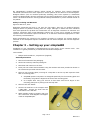
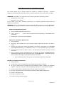
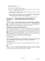
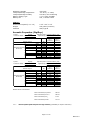
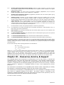
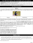
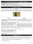
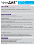
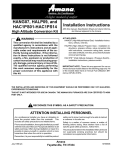
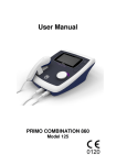
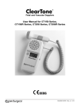
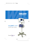
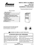
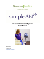
Vascular Diagnostic System User Manual Newman Medical 5350 Vivian Street, Unit C Arvada. CO 80002 1-800-267-5549 [email protected] www.newman-medical.com COMMON TERMINOLOGY ABI – Ankle Brachial Index – the ratio of the ankle systolic blood pressure divided by the brachial (arm) systolic blood pressure. DP – (or DPA) -- Dorsalis Pedis Artery --- the artery on top of the foot. Used in the ABI exam. MHz – Megahertz – Millions of cycles per second --the frequency of the sound transmitted by a vascular probe is measured in megahertz - 8 million cycles per second, for example. PAD – Peripheral Artery Disease – Typically atherosclerosis (also known as hardening of the arteries) in the leg. PPG – Photoplethysmography –detects the pulse using reflected light from a small emitter/detector combination. PT – (or PTA) – Posterior Tibial Artery – artery on the inside of the ankle used in the ABI exam. PVD – Peripheral Vascular Disease – Includes venous as well as arterial disease. PVR – Pulse Volume Recording – a means of evaluating the condition of the arteries by looking at a waveform of small changes in cuff pressure caused by pulses in the arteries under the cuff. Segmentals – Pressures and PVRs just like the ABI but done in more cuffs on the leg to assist in localizing the site of any occlusion. The Doppler probe can remain at the ankle for the pressures. TBI – Toe Brachial Index – the ratio of the pressure in the toe divided by the brachial pressure. It is generally measured with a small toe cuff and a PPG probe Contents Chapter 1 – About simpleABI ........................................................2 Chapter 2 – Safety .........................................................................2 Chapter 3 – Setting up your simpleABI .........................................3 Chapter 4 – simpleABI Reporting Software ...................................5 Chapter 5 – Performing Exams ......................................................6 Chapter 6 - Detailed Description..................................................14 Chapter 7 – Tips & Troubleshooting ............................................15 Chapter 8 – Maintenance and Cleaning ........................................15 Chapter 9 – Specifications ...........................................................16 Chapter 10 – Resources, Service, & Support................................18 Page 1 of 19 NM0018-G Chapter 1 – About simpleABI Congratulations on your purchase of a simpleABI System from Newman Medical. The simpleABI was designed to be the easiest and most intuitive system on the market for initial vascular assessment. We hope you find that to be the case. If not, please do not hesitate to call us and let us know how we can improve the product for you. What’s new in the simpleABI System Simple and intuitive PC based interface Direct to Computer reporting software for ease of reimbursement Chapter 2 – Safety Intended Use The simpleABI System was designed to aid in the diagnosis of peripheral arterial disease (PAD) through diagnostic exams including Ankle Brachial Index (ABI). Caution: Federal law restricts this device to sale by or on the order of a physician or other licensed practitioner. Contraindications Contraindications: Do not perform the ABI exam on someone suspected of having acute deep venous thrombosis, and do not take an arm pressure in an arm with a shunt or dialysis graft. Warning: The device is not to be used on or near the eyes. Warning: The device is for use only on intact skin. Warning: The device is not to be plugged into a telephone or modem system. Safety of the Blood pressure cuffs Inspect the cuffs for damage periodically. Do not leave a cuff inflated at high pressures for an extended period of time when on a patient. Do not inflate a cuff when it is not on a patient. Cuff covers may be washed by removing the bladders. Any open lesion with the potential for contamination should be covered with an impermeable dressing. Safety of Dopplers The simpleABI was designed according to National and International consensus safety standards. Throughout design of this product, safety was the paramount concern. In view of that, this product was designed according to the principle of ALARA (As Low As Reasonably Achievable). AIUM Statements As Low As Reasonably Achievable (ALARA) Principle Approved March 16, 2008 The potential benefits and risks of each examination should be considered. The ALARA (As Low As Reasonably Achievable) Principle should be observed when adjusting controls that affect the acoustical output and by considering transducer dwell times. Further details on ALARA may be found in the AIUM publication "Medical Ultrasound Safety." Prudent Use and Clinical Safety Approved March 19, 2007 Diagnostic ultrasound has been in use since the late 1950s. Given its known benefits and recognized efficacy for medical diagnosis, including use during human pregnancy, the American Institute of Ultrasound in Medicine herein addresses the clinical safety of such use: Page 2 of 19 NM0018-G No independently confirmed adverse effects caused by exposure from present diagnostic ultrasound instruments have been reported in human patients in the absence of contrast agents. Biological effects (such as localized pulmonary bleeding) have been reported in mammalian systems at diagnostically relevant exposures but the clinical significance of such effects is not yet known. Ultrasound should be used by qualified health professionals to provide medical benefit to the patient. Safety in Training and Research Approved March 19, 2007 Diagnostic ultrasound has been in use since the late 1950s. There are no confirmed adverse biological effects on patients resulting from this usage. Although no hazard has been identified that would preclude the prudent and conservative use of diagnostic ultrasound in education and research, experience from normal diagnostic practice may or may not be relevant to extended exposure times and altered exposure conditions. It is therefore considered appropriate to make the following recommendation: When examinations are carried out for purposes of training or research, the subject should be informed of the anticipated exposure conditions and how these compare with normal diagnostic practice. Chapter 3 – Setting up your simpleABI Installation of your simpleABI is straightforward but does require a few common tools. installation is typically handled by a trained Newman Medical salesperson. This Tools needed: Phillips head screwdriver, #2 preferred (supplied) Assembly Directions 1. Remove all materials from packaging. 2. Check that inventory matches packing list. 3. Place base with casters on the floor. 4. Insert pole into caster base and attach using the washers and screw provided as shown on the instructions provided with the stand. 5. Place PC onto mounting plate, ensuring all 4 loop tabs on PC line up with respective hook tabs on mounting plate. a. simpleABI systems computers are designed specifically for the mounting plate and the battery will guide the alignment of the PC and mounting plate. b. It is helpful when using your own PC to first check how the PC aligns on the mounting plate prior to placing hook and loop tabs. 6. Place all cuffs into basket. 7. Connect the PVR box to the computer with a USB cable. Connect the hose from the cuff inflator to the PVR box. 8. Attach Doppler probe to Doppler main unit with coiled cord. Slide Doppler into Doppler cradle on simpleABI pole. Page 3 of 19 NM0018-G FIELD INSTALLATION OF SIMPLEABI SOFTWARE This section applies only to systems where the software is installed in the field – computers shipped from Newman Medical already have the software loaded and this section does not apply. WARNING: simpleABI is only supported on the following Windows Operating Systems: Windows XP (32 or 64 bit) Windows 7 (32 or 64 bit) Do not install on any other operating systems prior to contacting Newman Medical Technical Support for information. WARNING: Use of other applications (word processing, games, internet) is not an appropriate use of a medical device and must be avoided to ensure proper operation of the simpleABI system. Software Installation Directions 1. Plug in included USB Flash Drive into PC 2. Copy *.msi to C:\ purchased) (.msi file will have different names depending on simpleABI system 3. Double Click *.msi file to begin installation PVR Driver Installation-Windows XP 1. Plug in PVR box. 2. At prompt, select ‘Install from a list or specific location (Advanced) and click the ‘Next>’ button 3. Check the box that says ‘Include this location in the search:’ and browse to C:\PROGRAM FILES\NEWMAN MEDICAL\***\PVRDRIVER, where *** is the simpleABI system purchased 4. Click OK and then Click the ‘Next>’ button. This will begin the install for the driver for the PVR boxes. 5. Driver should be properly installed and can be checked by opening simpleABI Reporting Software and clicking on either PVR button on an opened ABI Report. If installed properly, pop-up window will display ‘Left/Right PVR Device Connected’ a. If not installed properly, pop-up will read ‘Left/Right PVR Box Not Detected’ PVR Driver Installation-Windows 7 6. Plug in PVR box. 7. Double Click on icon in taskbar that says ‘Installing device driver software’ 8. On pop-up window click link that says ‘Skip obtaining driver software from Windows Update’. Click Yes on pop-up confirming skipping finding driver using Windows Update. 9. Click the ‘Start’ Button (Windows Logo) and click ‘Devices and Printers’ 10. Scroll to ‘Unspecified’ Devices and double click the Newman Medical PVR Device. 11. Click the ‘Hardware’ Tab 12. Click the ‘Properties’ button 13. Click the ‘Change Settings’ button Page 4 of 19 NM0018-G 14. Click the ‘Driver’ Tab 15. Click the ‘Update Driver’ button 16. Click ‘Browse my computer for driver software’ 17. Browse to ‘C:\Program Files\Newman Medical\***\pvrDriver and click the next button where *** is the simpleABI system purchased 18. Click ‘Install this driver software anyway’ on the Windows security window. This will begin the install for the driver for the PVR box. 19. Driver should be properly installed and can be checked by opening simpleABI Reporting Software and clicking on either PVR button on an opened ABI Report. If installed properly, pop-up window will display ‘Left/Right PVR Device Connected’ a. If not installed properly, pop-up will read ‘Left/Right PVR Box Not Detected’ Chapter 4 – simpleABI Reporting Software Start-up If the first screen is a windows background that says simpleABI Locked press Enter to get to the desktop. Find the simpleABI Reports icon on the computer desktop and select it. A blank screen with tabs on the top should come on. Select File and then New. Depending on the system chosen, you may have a choice of ABI, TBI, or Segmental exams. Select one and the exam will appear on the screen. Entering Doctor/Examiner/Practice Information Fill in the fields for patient information. Use the touch pad and click on appropriate Risk Factors and Current Symptoms. You may enter information about the physician, examiner, and ICD-9 codes, or you may choose from those available using the dropdown menu feature. You can add or delete items in the drop down choices. Under the EDIT menu and then choose Data Maintenance. You can fill in doctor, examiner, and practice information as you want it to appear on reports. There are some examples prefilled and you can add, edit, or delete these as you see necessary. To close the data maintenance (EDIT) form, select File\Close Form Saving Your Exam You can save your finished report as a PDF file using CTRL+S or select File\Save as. Files are appended with Patient ID and a timestamp to differentiate exams. This command automatically saves 3 exam types: PDF, TIFF, and a XML data file. Printing Your Exam You can print your exams directly to the computer’s default printer using CTRL+P or select File\Print Help Help is found by selecting Help/www.newman-medical.com. With an internet connection, you will be directed to Newman Medical’s home page where you can browse to our support pages with helpful hints on using your simpleABI. Page 5 of 19 NM0018-G Chapter 5 – Performing Exams ABI EXAMINATION Overview: The ABI has become the best known and standardized test for PAD. Fundamentally it is simply the systolic blood pressure taken with the cuff at the ankle divided by the systolic pressure with the cuff on the upper arm. Recent reviews 1 and reimbursement criteria require that the measurements be done with a Doppler using both the DP and PT arteries at the foot. A PVR waveform is also required for reimbursement. Contraindications: Do not perform the ABI exam on someone suspected of having acute deep vein thrombosis, and do not take an arm pressure in an arm with a shunt or dialysis graft. The cuff should not be applied over a distal bypass or over ulcers. Any open lesion posing suspected contamination should be covered with an impermeable dressing. Have the patient lie down in the supine position relaxed, head and heels supported in a comfortably warm room. Wrap appropriate sized cuffs (usually 12 cm on the arms and 10 cm on the ankles). On the arms apply the cuffs as you would for a normal blood pressure. On the legs, have the patient place their feet flat on the table with knees bent as you apply the cuff above their ankle. Cuffs should fit snugly so that fingers should slide between the cuff and limb with difficulty. The lower edge of the ankle cuff should be about an inch above the top of the medial malleolus (ankle bone). Although the system will allow you to take the pressures and waveforms in any order, try to be consistent. The recommendations of the review are to do right arm, right ankle, left ankle, finally left arm. Arm Pressure: Connect the hose from the PVR to the first arm cuff. Place the Doppler probe over either the radial (preferred) or the brachial artery. *HINT* Hold the probe close to the end. It also helps to rest your hand on the patient to keep the probe in place. One of the keys to a successful exam is being able to keep the probe in place as you inflate and deflate. If it moves you will not be able to hear the Doppler sounds return and you will have to repeat the inflation. Use the angled vascular adapter (Cheater™) to get the best signal and to keep the probe from moving during inflation and deflation. Move the probe slowly back and forth until the strongest arterial signal is heard. 1. Inflate the cuff until the Doppler signal disappears. Continue to inflate for about another 20mmHg. Slowly (about 2mmHg/second) deflate the cuff until the signal returns. Note the pressure at the moment that you hear the first sound return 1 Measurement and interpretation of the ankle-brachial index: a scientific statement from the American Heart Association. Circulation. 2012;126 Page 6 of 19 NM0018-G and enter that pressure into the brachial pressure box. This is the systolic pressure. After hearing the returning sound, rapidly deflate the cuff. 2. Obtain the PVR Waveform: Click on the box that says “Right PVR”. Move the cuff hose to the ankle cuff and inflate it to about 75 mmHg. Deflate it down to about 65mm – you should see a green bar on the screen above where the PVR waveform will be. The end of this bar should be about in the middle of the space, not at either end. Adjust it if necessary by inflating or deflating the cuff. Now click on the “Get Waveform” box and wait five seconds while the system gathers PVR data. The waveform should then appear. If it is satisfactory move on, if not just click on the box again and repeat. 3. Ankle PT Pressure: Obtain the ankle pressure using the Doppler at the PT artery. Place the Doppler probe over the PT artery and move it slowly back and Page 7 of 19 NM0018-G forth until the strongest signal is heard. As with the arm, now inflate and deflate the cuff noting when the signal returns and enter that into the PT box. 4. Ankle DP Pressure: Do the same with the probe over the DP and enter that pressure into the DP box. The DP is often harder to find; be sure not to press too hard as it is over boney structures and relatively easy to occlude. The system will automatically do the correct and recommended calculations of the ABI. Specifically it is the higher of the two ankle pressures divided by the higher of the two brachial pressures. Page 8 of 19 NM0018-G 5. Now move the hose to the left ankle cuff and take the PVR at that location as you did for the right cuff. Then take the left ankle pressures at the PT and DP and enter those values into the appropriate boxes 6. Finally move the hose to the left arm cuff and take that pressure like you did the right arm and enter that value into the brachial box. The interpretation of the ABI values is based on recent guidelines.2 *HINT* If the ankle pressure is high, above 200 mmHg, or the cuff cannot obliterate the Doppler sounds, this indicates that the artery may be incompressible due to calcification. SAVING/PRINTING REPORT When finished you may add comments in the comment section and choose Recommendations if desired. Save or print the report by going back to the File tab. Interpretation of PVR waveforms Pulse Volume Recording (PVR) is used to measure the change in pressure in the cuff caused by the small changes in volume that occur with each pulse. The analysis of the waveform is based on the shape of the waveform rather than the amplitude. PVRs are not affected by calcified arterial walls and are relatively easy to perform. Rapid Rise Prominent reflected wave notch Normal: Here is a good waveform with a rapid rise and a prominent reflected wave 2 A REPORT OF THE AMERICAN COLLEGE OF CARDIOLOGY FOUNDATION/AMERICAN HEART ASSOCIATION TASK FORCE ON PRACTICE GUIDELINES. CIRCULATION 2011; 124:2020–2045. Page 9 of 19 NM0018-G Another Normal Moderately Abnormal: Waveform starts to broaden and no reflected wave. (The first pulse may be an artifact but also may be an arrhythmia.) Moderate Abnormal Page 10 of 19 NM0018-G Abnormal: No reflected wave, slow rise. The cuff must have been slowly losing pressure as well because of the downward slope. Abnormal: Slow rise, little reflected wave – quite a bit of tremor “noise” Determining site of occlusion with PVR waveforms:3 A normal waveform at a site indicates that there is not likely any occlusive disease above that cuff. Abnormal at thigh: Probably aorto-iliac disease Normal thigh but abnormal calf (below knee): occlusive disease in superficial femoral and/or popliteal segments. Normal thigh and calf with abnormal ankle: suggests tibial disease Don’t be discouraged if measuring the ABI seems slow or clumsy at first. Like any procedure, the ABI becomes easier to do with practice. Segmental Examination 3 Daigle, Robert J., Techniques in Noninvasive Vascular Diagnosis, Summer Publishing, www.summerpublishing.com Page 11 of 19 NM0018-G Purpose: A segmental exam of the leg is an extension of the ABI exam. In this test, you can attempt to localize the site of an occlusion by taking the pressures and waveforms at more locations on the leg. By observing the difference in pressure between adjacent sites on the leg you can tell if there is an occlusion between those sites. A greater than 20mmHg difference between sites is considered positive for a significant stenosis in the artery between or under the cuff. Patient Preparation: The patient should be relaxed in a supine position for 5-10 minutes in a warm room. Explain the examination to the patient. This is an ideal time to enter patient information. Setting up On the computer desktop screen, select the simpleABI reports icon. When the screen opens click on the File tab, then New, and then select the Segmental report. Fill out the patient information, risk factors, ICD-9 codes, etc. Wrap appropriate cuffs at each site. Pressures Note: Current CPT guidelines (2013) for CPT code 93923 do not require that pressures be obtained at each cuff site on the leg if an ABI is performed using both ankle arteries and PVR waveforms are obtained at each leg cuff. This can significantly reduce the time necessary for this exam. (However, the pressures provide much of the clinical information about the site of a potential occlusion.) Also, it is quicker to use a PPG probe for the pressures. Reimbursement requires that the ankle pressures be done with a Doppler on both PT and DP. However, you can then use a PPG sensor on the great toe to then get the pressures at the other sites. Brachial Pressure: Attach the hose to the arm cuff. Place the Doppler probe at an angle to the skin over either the radial (preferred) or brachial artery. Use plenty of ultrasonic gel and slowly move the probe until the best signal is obtained. Inflate the cuff until you no longer hear the signal, and continue for an additional 20 mmHg. Slowly bleed pressure down until the signal returns and note the pressure-this is the systolic pressure. Rapidly deflate the cuff. Enter the systolic pressure into the respective brachial field on the report. Ankle Pressure (DP): Move the hose to the ankle cuff. Take a PVR Waveform as described below. Take an ankle pressure using the Doppler probe on the dorsalis pedis (DP) artery on top of the foot. Inflate the cuff to occlude the artery in the same manner you did on the arm, noting return pressure. Enter the systolic pressure into the respective DP field on the report. Ankle Pressure (PT): Place the Doppler probe on the posterior tibial (PT) artery behind the ankle bone. Occlude the artery in the same manner you have in the previous steps, noting return pressure. Enter the pressure in the PT field on report. Calf: Now move the hose and take the pressure (If desired, see note above) at the right calf, leaving the Doppler probe on the PT artery or using the PPG sensor on the great toe. Occlude the artery in the same manner as you have in the previous steps, noting return pressure. Enter the systolic pressure in respective field on report. Take a PVR Waveform as described below. Above knee: Now (if desired) move the hose and take the pressure above the right knee, leaving the Doppler probe on the posterior tibial (PT) artery or the PPG sensor on the toe. Occlude the artery in the same manner as you have in the previous steps, Page 12 of 19 NM0018-G noting return pressure. Record return pressure in respective field on report. Take a PVR Waveform as described below. Repeat the sequence for the left leg, starting at the arm, then the DP and PT at the ankle and moving up the leg to the other cuff sites. PVR Waveforms • Select the desired PVR waveform box by clicking on it. Attach the hose to that cuff and inflate to ~75mmHg and bleed to ~65. – the green bar will be about in the center of its box on the screen. Set aneroid on exam table when finished bleeding pressure to 65mmHg to avoid affecting waveforms with your movement. • Press or click appropriate PVR button. A pop-up window will appear, press or click ‘Get Waveform’. simpleABI Reporting software will take 5 seconds of PVR waveforms and return to form. You can click again on “Get Waveform” if you are not satisfied with the waveform. When finished, save the report. The TBI Examination Contraindications: Do not perform the TBI exam on someone suspected of having acute deep venous thrombosis, and do not take an arm pressure in an arm with a shunt or dialysis graft. Background: The TBI exam is typically performed after an ABI has been done, especially if the larger ankle arteries appear to be incompressible (pressure over 200mmHg) or anytime more information is needed about small vessel disease. The TBI is done using the PPG probe. The patient is supine and rested in a warm room. Setting up On the computer desktop, select the simpleABI icon. When the screen opens click on the File tab, then New, and then select TBI report. The TBI report form will come up. Wrap cuffs (12cm) on the arms. Wrap a small digit cuff on the great toe as far down towards the base as possible. Attach the PPG probe and sensor to the DigiDop, replacing the Doppler probe. Page 13 of 19 NM0018-G Pressures • Place the PPG sensor on the index finger with the sensor on the fleshy part of the finger. Wait until you get consistent beeps from the system. (Double beats will not affect the measurement.) • Attach the hose from the pump/PVR box to the arm cuff, inflate until you no longer hear the signal, and continue for an additional 20 mmHg. Slowly bleed pressure down until the signal returns and note that return pressure. This is the systolic pressure. Then rapidly deflate the cuff. Enter the pressure into the brachial field on the report. • Now move the PPG sensor to the right toe above the digit cuff and opposite the toenail. It may help reduce extraneous signals to tape the cord from the sensor to the foot. • Attach the hose to the digit cuff and inflate about 20mmHg past where the pulse beep disappears. Slowly deflate the cuff and note the pressure when the sound returns. Enter this pressure into the TOE pressure box on the screen. The TBI is automatically calculated. • Move the cuffs and PPG sensor to the left side of the body and repeat these steps. PVR Waveforms If you have already taken PVR waveforms during the ABI exam there is no need to repeat them. You can take them in this report. The waveforms are taken at the ankle. • • • Wrap 10cm cuffs around each ankle above the ankle bone. Attach the hose from the PVR box to the cuff. Click on the PVR box on the screen. Inflate the cuff to 75mmHg and then deflate to about 65mmHg. The green bar should be about in the center of its box on the screen. Click on Get Waveform and wait five seconds while the system collects data. The waveform will be displayed. You can click again on Get Waveform if you are not satisfied with the waveform. When finished, save the report. Chapter 6 - Detailed Description DigiDop Doppler – Operation and Use The DigiDop is designed to aid in diagnosis of vascular conditions including aiding in obtaining systolic pressures during an ABI examination. Main Unit The body of the unit is a one-piece enclosure. The unit was designed for comfort and ease-of-use during examinations. Each unit is tested to ensure the highest quality possible. Power On/Off Power to the unit is controlled by the POWER button located in the center of the unit. Pressing and releasing the button will cycle the unit through the power sequence. The LED in the power button will remain illuminated during operation. The DigiDop automatically turns itself off after 3 minutes of inactivity. This auto shut off feature preserves battery life and serves to eliminate complete battery drain in case of accidental failure to shut off the unit. Page 14 of 19 NM0018-G Battery Monitoring The DigiDop periodically checks the status of the batteries. When the power button LED flashes, the battery level is low and batteries should be charged immediately. Volume The DigiDop has multiple volume levels. These are adjusted by sliding the volume slider on the left hand side of the main unit. Recharge The simpleABI comes with a rechargeable DigiDop. Simply plug the AC adapter into the charging jack at the bottom of the DigiDop to begin charging unit. The unit may not be used while the batteries are being charged. It is recommended that to achieve a full charge the DigiDop is left plugged into the AC adapter overnight, however, quick charging for immediate use can be accomplished by plugging into the AC adapter for 15 minutes. Probes: 8 MHz – Vascular. simpleABI Systems come standard with an 8MHz probe designed for locating shallow lying vessels. The pen-tip sensor face aids in the location of specific vessels during examination. 5 MHz – Vascular. An optional 5MHz probe is available for simpleABI Systems and designed for locating deeper lying vessels. The wider sensors may aid in maintaining the probe location on the vessel during examination. PPG – The Photoplethysmograph probe uses the absorption of infrared light by blood cells in the blood to produce an audible beep each time it detects a vascular pulse in the near surface vessels. Obtaining Doppler Signals Caution: For any examination utilizing a Doppler, it is essential that an adequate supply of gel is used to transmit the ultrasound energy from the probe to the surface of the skin. Re-apply more gel if it starts to dry out or spread so thinly that an air gap occurs between the probe and the skin. It is not necessary to cover the entire surface of the probe, only the probe face. Applying too much gel makes the unit difficult to clean and does not aid in the performance of the probe. Given the small area of the vascular probes, the strength of the Doppler signal is highly location specific. Chapter 7 – Tips & Troubleshooting Poor Sound Quality Inadequate gel use-apply more gel Probe location-search for vascular sounds as described in Chapter 5 – Performing Exams Power Button LED flashing The voltage of the batteries is low. Charge the batteries as soon as possible. Chapter 8 – Maintenance and Cleaning WARNING: The simpleABI components are not designed for liquid immersion. Do not soak or drop the Doppler main unit or probes in liquid. WARNING: The DigiDop is not designed for sterilization processes such as autoclaving or gamma radiation. WARNING: The DigiDop is not intended to be used on open skin. If there is evidence of open wound contamination, disinfect the probe before using again as described below. The DigiDop requires very little maintenance. It is important, however, for the continued functionality of the unit and the health of the patients to that the unit is cleaned and examined regularly as follows: Page 15 of 19 NM0018-G After every examination Excess gel should be wiped off after each examination. Unit should be cleaned with a damp water or alcohol based wipe. Mild soap or detergent can be used. In particular pay attention to any surface openings on the unit including, but not limited to, the speaker grill, the battery compartment, the audio output, and the parting line between the front and back shell. Practitioners should wash hands and change gloves after every exam. hospital guidelines for cleaning and disinfection policies. Please follow local and To disinfect unit, use an isopropyl alcohol wipe or spray, such as Parkers Labs Protex® and follow the manufacturer’s instructions. Store unit in a clean area free from dust and debris in an indoor environment. If storing the unit for a prolonged period of 90 days or longer without use, please remove the batteries prior to storage. Periodically Inspect the unit for signs or cracks or breaks in the surface housing. If any sign of cracking or damage is evident, use of the unit should be discontinued. Please contact Newman Medical for service. Battery Replacement WARNING: Replace rechargeable batteries only with approved rechargeable batteries. call customer service or visit our website for further information. Please WARNING: The DigiDop uses AA batteries. Do not attempt to use any other size batteries in the unit. Open the battery compartment by sliding the battery compartment door to the side. Remove the drained batteries by pulling one of batteries out of the unit from the positive (button) end of the battery. Replace the batteries by paying close attention to the polarity indicators on the battery and the polarity indicators on the battery door. Align the batteries according to the symbols located in the battery compartment. Please note: If the batteries have been incorrectly inserted, the DigiDop will not work, but will NOT be damaged. Please re-insert the batteries correctly. Chapter 9 – Specifications Level of Protection against electrical shock Type B Applied Part; Class II Equipment Designed to meet the following standards: IEC60601-1, IEC60601-2, IEC60601-2-37 SimpleABI System Height (inclusive) Weight (inclusive) 107 cm (42 inches) 5.5 kgs (12 pounds) Transport/Storage Temperature Transport/Storage Humidity Battery Life -20-50C (-4-122F) 5%-90%, non-condensing 10 hours DigiDop Dimensions-imperial (h x w x d) Weight (with batteries) Operating Temperature 6” x 2.5” x 1.25” 370 grams (13 ounces) 10–40C (50-104F) Page 16 of 19 NM0018-G Operating Humidity Transport/Storage Temperature Transport/Storage Humidity Battery Voltage, type Battery Life 30%-75% -20-50C (-4-122F) 5%-90%, non-condensing 3 x 1.2 volts, AA NiMH 500, 1-minute exams PVR Box Dimensions-imperial (h x w x d) Weight Interface 2.75” x 2.0” x 0.8” 200 grams (8 ounces) USB, Type B Acoustic Properties (DigiDop) System: Transducer Model: DigiDop 5MHz Operating Mode: Continuous Wave (CW) Application(s): Peripheral Vascular Acoustic Output Global Maximum Value pr.3 Wo Associated Acoustic fc zsp Parameters Beam Dimensions PD PRF EBD System: Transducer Model: DigiDop 8MHz, narrow ISPTA.3 ISPPA.3 (mW/cm2) 86.4 (mW/cm2) 86.4 9.26 5.61 1.10 0.154 0.540 9.26 5.61 1.10 0.154 0.540 CW n/a 5.61 1.10 CW n/a 1.052 0.526 Operating Mode: Continuous Wave (CW) Application(s): Peripheral Vascular Acoustic Output Global Maximum Value pr.3 Wo Associated Acoustic fc zsp Parameters Beam Dimensions PD PRF EBD (Mpa) (mW) (MHz) (cm) x-6 (cm) y-6 (cm) (usec) (Hz) Az. (cm) Ele. (cm) MI 0.0223 0.041 (Mpa) (mW) (MHz) (cm) x-6 (cm) y-6 (cm) (usec) (Hz) Az. (cm) Ele. (cm) MI 0.0495 0.0923 ISPTA.3 ISPPA.3 (mW/cm2) 555 (mW/cm2) 555 9.02 7.84 0.50 0.231 0.121 9.02 7.84 0.50 0.231 0.121 CW n/a 7.84 0.50 CW n/a 0.203 0.457 Measurement Uncertainties: ISPTA.3 Total uncertainty for power: 28.2% Total uncertainty for ISPTA: 28.2% Total uncertainty for fc: 2.0% Total uncertainty for MI: 14.1% derated spatial-peak temporal-average intensity (milliwatts per square centimeter). Page 17 of 19 NM0018-G ISPPA.3 derated spatial-peak pulse-average intensity (watts per square centimeter). The value of IPA.3 at the position of global maximum MI (IPA.3@MI) may be reported instead of ISPPA.3 if the global maximum MI is reported. MI Mechanical Index. The value of MI at the position of ISPPA.3, ([email protected]) may be reported instead of MI (global maximum value) if ISPPA.3 is ≤ 190W/cm2 . pr.3 derated peak rarefactional pressure (megapascals) associated with the transmit pattern giving rise to the value reported under MI. Wo ultrasonic power (milliwatts). For the operating condition giving rise to ISPTA.3, Wo is the total time-average power; for the operating condition subject to reporting under ISPPA.3, Wo is the ultrasonic power associated with the transmit pattern giving rise to the value reported under ISPPA.3. fc center frequency (MHz). For MI and ISPPA.3, fc is the center frequency associated with the transmit pattern giving rise to the global maximum value of the respective parameter. For ISPTA.3, for combined modes involving beam types of unequal center frequency, fc is defined as the overall range of center frequencies of the respective transmit patterns. zsp the axial distance at which the reported parameter is measured (centimeters). x-6, y-6 are respectively the in-plane (azimuthal) and out-of-plane (elevational) -6 dB dimensions in the x-y plane where zsp is found (centimeters). PD pulse duration (microseconds) associated with the transmit pattern giving rise to the reported value of the respective parameter. PRF the pulse repetition frequency (Hz) associated with the transmit pattern giving rise to the reported value of the respective parameter. EBD the entrance beam dimensions for the azimuthal and elevational planes (centimeters). EDS the entrance dimensions of the scan for the azimuthal and elevational planes (centimeters). The reporting values for ultrasonic power, W0, and non-derated spatial average temporal average ISATA required by paragraph 2.1.2 of the FDA Guidance [3] as well as the derated spatial-peak temporal-average intensity, ISPTA.3, provided for reference only, are calculated for all probes as illustrated in the sample calculations below. For Non-Auto scanning modes reporting parameters are calculated as: W0 = ISPTA.0 * PF ISATA.0 = W0/(entrance beam area) ISPTA.3 = ISPTA.0 * e -0.069 fc z Where ISPTA.0, is the non-derated spatial-peak temporal-average intensity, ISATA.0 is the nonderated spatialaverage temporal-average intensity at the transducer face and ISPTA.3, is the derated spatial-peak temporalaverage intensity, fC, the waveform center frequency, z, the axial distance between the probe and hydrophone, PF, the power factor which is calculated by integrating the normalized cross axis and raster scan data selecting the largest PF value, which is an “effective area” used to calculate W0, the ultrasonic power. Chapter 10 – Resources, Service, & Support The simpleABI System and components are guaranteed to be free from defects in material and workmanship for 2 years from the original sale of the device. This guarantee includes all parts and labor required to repair or replace the unit, including shipping the unit back to the customer. Customer is responsible for the adequate packaging and return of the unit for servicing. Products will be repaired or replaced in a reasonable amount of time, to be determined by service personnel. The manufacturer and distributor of a simpleABI System assume neither responsibility nor liability for incidental or consequential damages arising from the purchase of this product. The manufacturer and distributor of simpleABI Systems are not responsible for damages occurring from misuse or neglectful handling of the device. Any abuse, neglect, or alteration of the equipment, including dismantling of the unit (other than by trained service personnel), from its original specifications nullify all stated and implied warranties. To return a unit for servicing: Page 18 of 19 NM0018-G 1. Call customer service for a return authorization. 2. Clean the product prior to packing and shipping. 3. Adequately package and return the unit to: Newman Medical Attn: Service 5350 Vivian Street, Unit C Arvada, CO 80002 800-267-5549 Page 19 of 19 NM0018-G