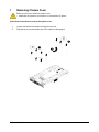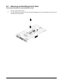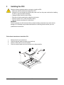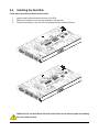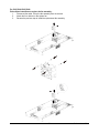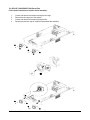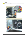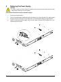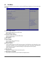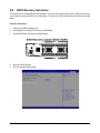
1
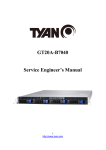
Relion 2808GT Technical Guide Rev. 1.0 PENGUIN COMPUTING www.penguincomputing.com | 1-888-PENGUIN (736-4846) | twitter:@PenguinHPC GS-R22PHE Dual LGA2011 socket motherboard for Intel® Xeon® E5-2600 processors Service Guide Rev. 1.0 Copyright © 2014 GIGA-BYTE TECHNOLOGY CO., LTD. All rights reserved. The trademarks mentioned in this manual are legally registered to their respective owners. Disclaimer Information in this manual is protected by copyright laws and is the property of GIGABYTE. Changes to the specifications and features in this manual may be made by GIGABYTE without prior notice. No part of this manual may be reproduced, copied, translated, transmitted, or published in any form or by any means without GIGABYTE's prior written permission. Documentation Classifications In order to assist in the use of this product, GIGABYTE provides the following types of documentations: For detailed product information, carefully read the Serice Guide. For product-related information, check on our website at: http://www.gigabyte.com Preface Before using this information and the product it supports, please read the following general information. 1. 2. This Service Guide provides you with all technical information relating to the BASIC CONFIGURATION decided for GIGABYTE’s “global” product offering. To better fit local marketrequirements and enhance product competitiveness, your regional office MAY have decided toextend the functionality of a machine (e.g. add-on card, modem, or extra memory capability).These LOCALIZED FEATURES will NOT be covered in this generic service guide. In suchcases, please contact your regional offices or the responsible personnel/channel to provide youwith further technical details. Please note WHEN ORDERING SPARE PARTS, you should check the most up-to-date informationavailable on your regional web or channel. For whatever reason, if a part number change is made,it will not be noted in the printed Service Guide. For GIGABYTE-AUTHORIZED SERVICEPROVIDERS, your GIGABYTE office may have a DIFFERENT part number code to thosegiven in the FRU list of this printed Service Guide. You MUST use the list provided by yourregional GIGABYTE office to order FRU parts for repair and service of customer machines. Table of Contents Box Contents Safety, Care and Regulatory Information Chapter 1 Hardware Installation 1-1 1-2 6 7 10 Installation Precautions Product Specifications 10 11 Chapter 2 System Hardware Installation 2-1 2-2 2-3 2-4 2-5 2-6 2-7 13 Removing Chassis Cover Removing and Installing the Fan Duct Installing the CPU Installing the Heat Sink Installing the Memory 14 15 16 17 19 2-5-1 Four Channel Memory Configuration 19 2-5-2 Installing a Memory 20 Installing the PCI Expansion Card 2-6-1 Installing Add-on Card (GC-MSLZ1/PCIE_6/Optional) 2-6-2 Installing Add-on Card (GC-MSLZ2/PCIE_5/Optional) Installing the Hard Disk Drive 21 26 27 28 2-8 Replacing the FAN Assemblly 29 2-9 Replacing the Power Supply 34 Chapter 3 System Appearance 35 1Front View 2Rear View 3-3 Front Panel LED and Buttons 3-4 Rear System LAN LEDs 3-5 Hard Disk Drive LEDs 3-6 Hard Disk Back Plane Board Jumper Setting 3-7 Cable Routing 35 36 37 38 39 40 41 Chapter 4 Motherboard Components 42 Chapter 5 BIOS Setup 45 4-1 4-2 5-1 GA-7PPSP1 Motherboard Components Jumper Setting The Main Menu 42 44 47 -4- 5-2 Advanced Menu 5-2-1 49 PCI Configuration 50 5-2-1-1 PCI Express Settings 52 5-2-2 Runtime Error Logging 54 5-2-3 CPU Configuration 55 5-2-3-1 CPU Power Management Configuration 58 5-2-4 5-2-5 5-2-6 5-2-7 5-2-8 5-2-9 Fan Configuration 60 USB Configuration 61 SATA Configuration 62 SAS Configuration 64 Info Report Configuration 65 Super IO Configuration 66 5-2-10 Serial Port Console Redirection 68 5-2-11 Network Stack 71 5-2-12 Intel (R) I350 Gigabit Network Connection 3 Chipset Menu 1 1 2 3 2 5-3-3 5-4 72 74 North Bridge IOH Configuration QPI Configuration DIMM Information South Bridge ME Subsystem 75 78 80 81 82 84 Security Menu 855-5 ServerManagementMenu 86 5-5-1 5-5-2 5-5-3 5-5-4 BMC LAN Configuration 87 BMC Function 88 View FRU Information 89 System Event Log 90 6Boot Menu 1 2 91 CSM16 Parameters CSM Parameters 93 94 7Exit Menu 95 5-8 BIOS Beep Codes 96 5-9 BIOS Recovery Instruction 97 -5- Box Contents GS-R22PE System Driver CD RAID Key (Optional) • The box contents above are for reference only and the actual items shall depend on the product package you obtain. The box contents are subject to change without notice. • The motherboard image is for reference only. -6- Safety, Care and Regulatory Information Important safety information Read and follow all instructions marked on the product and in the documentation before you operateyour system. Retain all safety and operating instructions for future use. • The product should be operated only from the type of power source indicated on the rating label.* If your computer has a voltage selector switch, make sure that the switch is in the proper position foryour area. The voltage selector switch is set at the factory to the correct voltage. • • The plug-socket combination must be accessible at all times because it serves as the main disconnecting device. All product shipped with a three-wire electrical grounding-type plug only fits into a grounding-type poweroutlet. This is a safety feature. The equipment grounding should be in accordance with local and nationalelectrical codes. The equipment operates safely when it is used in accordance with its marked electricalratings and product usage instructions • • Do not use this product near water or a heat source.* Set up the product on a stable work surface or so as to ensure stability of the system. Openings in the case are provided for ventilation. Do not block or cover these openings. Make sure youprovide adequate space around the system for ventilation when you set up your work area. Never insertobjects of any kind into the ventilation openings. • • To avoid electrical shock, always unplug all power cables and modem cables from the wall outletsbefore removing covers. Allow the product to cool before removing covers or touching internal components. Precaution for Product with Laser Devices Observe the following precautions for laser devices: • Do not open the CD-ROM drive, make adjustments, or perform procedures on a laser device other than those specified in the product's documentation. • Only authorized service technicians should repair laser devices. Precaution for Product with Modems, Telecommunications, ot Local AreaNetwork Options Observe the following precautions for laser devices: • Do not connect or use a modem or telephone during a lightning storm. There may be a risk of electricalshock from lightning. • • • • To reduce the risk of fire, use only No. 26 AWG or larger telecommunications line cord. Do not plug a modem or telephone cable into the network interface controller (NIC) receptacle. Disconnect the modem cable before opening a product enclosure, touching or installing internalcomponents, or touching an uninsulated modem cable or jack. Do not use a telephone line to report a gas leak while you are in the vicinity of the leak. -7- Federal Communications Commission (FCC) Statement Warning This is a class A product. In a domestic environment this product may cause radiointerferenceIn which case the user may be required to take adequate measures. This equipment has been tested and found to comply with the limits for a Class A digital device,pursuant to Part 15 of the FCC Rules. These limits are designed to provide reasonable protection againstharmful interference when the equipment is operated in a commercial environment. This equipmentgenerates, uses, and can radiate radio frequency energy and, if not installed and used in accordance withthe instruction manual, may cause harmful interference to radio communications. Operation of thisequipment in a residential area is likely to cause harmful interference in which case the user will berequired to correct the interference at his own expense.Properly shielded and grounded cables and connectors must be used in order to meet FCC emissionlimits. Neither the provider nor the manufacturer are responsible for any radio or television interferencecaused by using other than recommended cables and connectors or by unauthorized changes ormodifications to this equipment. Unauthorized changes or modifications could void the user's authority tooperate the equipment. This device complies with Part 15 of the FCC Rules. Operation is subject to the following two conditions: (1)this device may not cause harmful interference, and (2)this device must accept any interference received, including interference that may cause undesired operation. Canadian Department of Communications Compliance Statement This digital apparatus does not exceed the Class A limits for radio noise emissions from digitalapparatus as set out in the radio interference regulations of Industry Canada.Le present appareil numerique n'emet pas de bruits radioelectriques depassant les limites applicables auxappareils numeriques de Classe A prescrites dans le reglement sur le brouillage radioelectrique edicte parIndustrie Canada. Class A equipment This device has been tested and found to comply with the limits for a class A digital device pursuantPart 15 of the FCC Rules. These limits are designed to provide reasonable protection againstharmful interference when the equipment is operated in a commercial environment. This equipmentgenerate, uses, and can radiate radio frequency energy, and if not installed and used in accordancewith the instructions, may cause harmful interference to radio communication. Operation of thisequipment in a residential area is likely to cause harmful interference, in which case the user will berequired to correct the interference at personal expence. However, there is no guarantee that interference will not occur in a particular installation. If thisdevice does cause harmful interference to radio or television reception, which can be determined bytuning the device off and on, the user is encouraged to try to correct the interference by on or more ofthe following measures: • • • Reorient or relocate the receiving antenna Increase the separation between the device and receiver Connect the device into an outlet on a circuit different from that to which the receiver isconnected'Consult the dealer or an experienced radio/television technician for help. -8- WEEE Symbol Statement The symbol shown below is on the product or on its packaging, which indicates that this product must not be disposed of with other waste. Instead, the device should be taken to the waste collection centers for activation of the treatment, collection, recycling and disposal procedure. The separate collection and recycling of your waste equipment at the time of disposal will help to conserve natural resources and ensure that it is recycled in a manner that protects human health and the environment. For more information about where you can drop off your waste equipment for recycling, please contact your local government office, your household waste disposal service or where you purchased the product for details of environmentally safe recycling. w When your electrical or electronic equipment is no longer useful to you, "take it back" to your local or regional waste collection administration for recycling. w If you need further assistance in recycling, reusing in your "end of life" product, you may contact us at the Customer Care number listed in your product's user's manual and we will be glad to help you with your effort. Battery Warning: Incorrectly installing a battery or using incompatible battery may increase the risk of ifre explosion. Replace the battery only with the same or equivalent type. • Do not disassemble, crush, punchture batteries. • Do not store or place your battery pack next to or in a heat source such as a fire, heatgenerating appliance, can or exhaust vent. Heating battery cells to temperatures above 65 oC (149oF) can cause explosion or fire. • Do not attempt to open or service batteries. Do not dispose of batteries in a fire or with household waste. -9- Chapter 1 1 Hardware Installation Installation Precautions The motherboard/system contain numerous delicate electronic circuits and components which can become damaged as a result of electrostatic discharge (ESD). Prior to installation, carefully read the service guide and follow these procedures: • Prior to installation, do not remove or break motherboard S/N (Serial Number) sticker or warranty sticker provided by your dealer. These stickers are required for warranty validation. • Always remove the AC power by unplugging the power cord from the power outlet before installing or removing the motherboard or other hardware components. • When connecting hardware components to the internal connectors on the motherboard, make sure they are connected tightly and securely. • When handling the motherboard, avoid touching any metal leads or connectors. • It is best to wear an electrostatic discharge (ESD) wrist strap when handling electronic components such as a motherboard, CPU or memory. If you do not have an ESD wrist strap, keep your hands dry and first touch a metal object to eliminate static electricity. • Prior to installing the motherboard, please have it on top of an antistatic pad or within an electrostatic shielding container. • Before unplugging the power supply cable from the motherboard, make sure the power supply has been turned off. • Before turning on the power, make sure the power supply voltage has been set according to the local voltage standard. • Before using the product, please verify that all cables and power connectors of your hardware components are connected. • To prevent damage to the motherboard, do not allow screws to come in contact with the motherboard circuit or its components. • Make sure there are no leftover screws or metal components placed on the motherboard or within the computer casing. • Do not place the computer system on an uneven surface. • Do not place the computer system in a high-temperature environment. • Turning on the computer power during the installation process can lead to damage to system components as well as physical harm to the user. • If you are uncertain about any installation steps or have a problem related to the use of the product, please consult a certified computer technician. Hardware Installation - 10 - 1-2 Product Specifications CPU Chipset Memory LAN Expansion Slot Onboard Graphics Mass Storage System Fans USB Internal Connectors Support for Intel® Xeon® E5-2600 series processors in the LGA2011 package L3 cache varies with CPU Supports QuickPath Interconnect up to 8GT/s Enhanced Intel SpeedStep Technology (EIST) Support Intel Virtualization Technology (VT) Intel® C602 (Patsburg-A) Chipset 16 x 1.35V/1.5V DDR3 DIMM sockets supporting up to 128GB (UDIMM) and 512GB (RDIMM) of system memory 16 x 1.35V/1.5V DDR3 LRDIMM sockets supporting up to 512GB of system memory Four channel memory architecture Support for 800/1066/1333/1600 memory modules Support for ECC RDIMM/ UDIMM/ LRDIMM memory modules Intel® I350 supports 10/100/1000 Mbps 1 x KVM management LAN port 4 x PCI Express x16 slots, running at x16 (Gen3/PCIE_1/PCIE_2/PCIE_3/ PCIE_4) 1 x PCI Express x16 slot, running at x8 (Gen2/PCIE_5/Proprietary slot) 1 x PCI Express x8 slot, running at x8 (Gen2/PCIE_6/Proprietary slot) ASPEED® AST2300 supports 128MB VRAM 8 x 2.5” Hot-Swap SATA/SAS HDDs Support for Intel IRSTe SATA RAID 0, RAID 1, RAID 5, RAID 10 8 x 80x80x38mm 15000rpm Up to 4 USB 2.0/1.1 ports (2 on the back panel, 2 additional ports via the USB brackets connected to the internal USB headers) 1 x 18-pin ATX main power connector 2 x 14-pin ATX 12V power connectors 2 x SATA 6Gb/s connectors 8 x SATA 3Gb/s connectors 2 x Front panel headers 1 x HDD back plane board header 1 x SAS SGPIO header 1 x SATA SGPIO header 1 x Serial port header 1 x USB 2.0/1.1 header 1 x TPM module connector 1 x SCU KEY header 1 x IPMB connector - 11 - Hardware Installation Rear Panel I/O 2 x USB 2.0/1.1 ports 2 x 1G RJ-45 LAN ports 1 x 10/100 dedicated management LAN port 1 x Serial port 1 x VGA port 1 x Power switch button 1 x ID switch button 1 x Reset button 1 x NMI button 1 x System status LED Front Panel LED/Buttons 1 x Power button/LED 1 x ID button/LED 1 x Reset button 2 x LAN LED 1 x HDD Status LED 1 x System LED I/O Controller ASPEED® AST2300 BMC chip System voltage detection CPU/System temperature detection 1 x 64 Mbit flash AMI BIOS Hardware Monitor BIOS Environment Ambient Temperature Operating Temperature: 10oC to 35oC Non-operating Temperature: -40oC to 60oC 10-80% operating Humidity (Non-condensing) Relative Humidity System 871Wx86Hx482D (mm) Dimension Electrical 2 x Hot-plug 2U PSU 1600W 100-240VAC at 80 plus Platinum level Power Supply Intel C600 Upgrade ROM SKUs: Upgrade ROM SKU# Patsburg-A; no upgrade ROM 1 2 SCU Ports Protocol Enabled Intel RSTe SAS RAID 5 4 ports SATA Only SATA RAID 5 4 ports 4 ports SATA/SAS SATA/SAS No Yes * GIGABYTE reserves the right to make any changes to the product specifications and product-related information without prior notice. Hardware Installation - 12 - Chapter 2 System Hardware Installation Pre-installation Instructions Perform the steps below before you open the server or before you remove or replaceany component. • Back up all important system and data files before performing any hardwareconfiguration. • Turn off the system and all the peripherals connected to it. • Locate the pin one of the CPU. The CPU cannot be inserted if oriented incorrectly. (Or you may locate the notches on both sides of the CPU and alignment keys on the CPU socket.) • Apply an even and thin layer of thermal grease on the surface of the CPU. • Do not turn on the computer if the CPU cooler is not installed, otherwise overheating and damage of the CPU may occur. • Set the CPU host frequency in accordance with the CPU specifications. It is not recommended that the system bus frequency be set beyond hardware specifications since it does not meet the standard requirements for the peripherals. If you wish to set the frequency beyond the standard specifications, please do so according to your hardware specifications including the CPU, graphics card, memory, hard drive, etc. - 13 - Hardware Installation 1 Removing Chassis Cover Before you remove or install the system cover • Make sure the system is not turned on or connected to AC power. Follow these instructions to remove the system cover: 1. 2. Loosen and remove the screws securing the top cover. Slide the back cover toward the rear of the chassis to disengage it. 1 1 Hardware Installation 2 - 14 - 2-2 Removing and Installing the Fan Duct Follow these instructions to remove/install the fan duct: 1. 2. Lift up to remove the fan duct To install the fan duct, align the fan duct with the guiding groove. Push down the fan duct into chassis until its firmly seats - 15 - Hardware Installation 3 Installing the CPU Read the following guidelines before you begin to install the CPU: • Make sure that the motherboard supports the CPU. • Always turn off the computer and unplug the power cord from the power outlet before installing the CPU to prevent hardware damage. • Unplug all cables from the power outlets. • Disconnect all telecommunication cables from their ports. • Place the system unit on a flat and stable surface. • Open the system according to the instructions. WARNING! Failure to properly turn off the server before you start installing components may cause serious damage. Do not attempt the procedures described in the following sections unless you are a qualified service technician. Follow these instructions to install the CPU: 1. 2. 3. 4. Release then lift up the load lever. Open the retention plate to expose the socket body. Insert the CPU with the correct orientation. Close the retention plate and close the lever to the locked position. 1 2 3 4 Hardware Installation - 16 - 2-4 Installing the Heat Sink Follow these instructions to install the heat sinks: 1. 2. 3. Apply thermal compound evenly on the top of the CPU. Remove the protective cover from the underside of the heat sink. Place the heat sink(s) on top of the CPU and tighten the four positioning screws. CPU0 CPU1 CPU0 and CPU1 use the different CPU heat sinks. Please see the following table for installing the correct CPU heat sink. - 17 - Hardware Installation Hardware Installation CPU1 P/N: 25ST1-443101-T4R CPU1 CPU0 - 18 - REAR FRONT CPU0 P/N: 25ST1-463200-T4R 5 Installing the Memory Read the following guidelines before you begin to install the memory: • Make sure that the motherboard supports the memory. It is recommended that memory of the same capacity, brand, speed, and chips be used. • Always turn off the computer and unplug the power cord from the power outlet before installing the memory to prevent hardware damage. • Memory modules have a foolproof design. A memory module can be installed in only one direction. If you are unable to insert the memory, switch the direction. 2-5-1 Four Channel Memory Configuration The system provides 16 DDR3 memory sockets for per CPU and supports Four Channel Technology. When the memory is installed, the BIOS will automatically detect the specifications and capacity of the memory. Enabling Four Channel memory mode will be triple of the original memory bandwidth. The sixteen DDR3 memory sockets are divided into four channels each channel has two memory sockets as following: Channel 1: DDR3_P0_A0/DDR3_P0_A1 (For pimary CPU); DDR3_P1_E0/DDR3_P1_E1 (For secondary CPU) Channel 2: DDR3_P0_B0/DDR3_P0_B1 (For pimary CPU); DDR3_P1_F0/DDR3_P1_F1 (For secondary CPU) Channel 3: DDR3_P0_C0/DDR3_P0_C1 (For pimary CPU); DDR3_P1_G0/ DDR3_P1_G1 (For secondary CPU) Channel 4: DDR3_P0_D0/DDR3_P0_D1 (For pimary CPU); DDR3_P1_H0/DDR3_P1_H1 (For secondary CPU) DDR3_P0_C0 DDR3_P0_C1 DDR3_P0_D0 DDR3_P0_D1 DDR3_P1_E0 DDR3_P1_E1 DDR3_P1_F0 DDR3_P1_F1 DDR3_P0_B1 DDR3_P0_B0 DDR3_P0_A1 DDR3_P0_A0 DDR3_P1_H1 DDR3_P1_H0 DDR3_P1_G1 DDR3_P1_G0 25 A A K A R B Y B E B K R 15 - 19 - Hardware Installation 2 Installing a Memory Before installing a memory module, make sure to turn off the computer and unplug the power cord from the power outlet to prevent damage to the memory module. Be sure to install DDR3 DIMMs on this motherboard. Follow these instructions to install the Memory: 1. 2. 3. Insert the DIMM memory module vertically into the DIMM slot, and push it down. Close the plastic clip at both edges of the DIMM slots to lock the DIMM module. Reverse the installation steps when you want to remove the DIMM module. 1 2 2 Hardware Installation - 20 - 6 Installing the PCI Expansion Card • Voltages can be present within the server whenever an AC power source is connected. This voltage is present even when the main power switch is in the off position. Ensure that the system is powered-down and all power sources have been disconnected from the server prior to installing a PCI card. Failure to observe these warnings could result in personal injury or damage to equipment. For GPU0/GPU1/GPU6/GPU7 Follow these instructions to install PCI Expansion card: 1. Loosen and remove the screws securing the PCI cage. 2. Pull the two plastic handles to lift up the PCI cage from the system. 3. Insert the card into the selected slot and secure the expansion card with screw. Make sure that the card is properly seated. 4. Secure the PCI expansion cards in place with screws. Top: GPU Card #6 (Slot 1) Bottom: GPU Card #7 (Slot 2) Front Rear Top: GPU Card #0 (Slot 1) Bottom: GPU Card #1 (Slot 2) 1 1 2 2 - 21 - Hardware Installation 4 3 PCIE_1 (Slot 1) 2 x 3 Power cable 2 x 4 Power cable For Slot 1 PCIE_2 (Slot 2) 2 x 3 Power cable 2 x 4 Power cable For Slot 2 • If the GPGPU card supports 225W, connect 2 x 4 power cable. • If the GPGPU card supports 300W, connect 2 x 4 and 2 x 3 power cables. - 22 - Hardware Installation For GPU2/GPU3/GPU4/GPU5 Follow these instructions to install PCI Expansion card: 1. Loosen and remove the screws securing the PCI cage. 2. Pull the two plastic handles to lift up the PCI cage from the system. 3. Insert the card into the selected slot and secure the expansion card with screw. Make sure that the card is properly seated. 4. Secure the PCI expansion cards in place with screws. Top: GPU Card #5 (Slot 2) Bottom: GPU Card #4 (Slot 1) Front Rear Top: GPU Card #3 (Slot 2) Bottom: GPU Card #2 (Slot 1) 1 Front Rear - 23 - Hardware Installation 1 2 4 3 Hardware Installation - 24 - 2 PCIE_1 (Slot 1) PCIE_2 (Slot 2) 2 x 3 Power cable 2 x 4 Power cable For Slot 2 2 x 3 Power cable 2 x 4 Power cable For Slot 1 • Please insert the PCI cage into the selected slot with the correct orientation. See illustrated below for instruction. • If the GPGPU card supports 225W, connect 2 x 4 power cable. • If the GPGPU card supports 300W, connect 2 x 4 and 2 x 3 power cables. Hardware Installation - 25 - 1 Installing Add-on Card (GC-MSLZ1/PCIE_6/Optional) • Voltages can be present within the server whenever an AC power source is connected. This voltage is present even when the main power switch is in the off position. Ensure that the system is powered-down and all power sources have been disconnected from the server prior to installing a PCI card. Failure to observe these warnings could result in personal injury or damage to equipment. Follow these instructions to install Add-on card: 1. Secure the stand-off on the motherboard with screws. 2. Attach the interposer card to the add-on card. Insert the add-on card into the selected slot (PCIE_6) and secure the card with screws. Make sure that the card is properly seated. 3. Secure the add-on card in place with screws. 3 2 1 Hardware Installation - 26 - 2 Installing Add-on Card (GC-MSLZ2/PCIE_5/Optional) • Voltages can be present within the server whenever an AC power source is connected. This voltage is present even when the main power switch is in the off position. Ensure that the system is powered-down and all power sources have been disconnected from the server prior to installing a PCI card. Failure to observe these warnings could result in personal injury or damage to equipment. Follow these instructions to install Add-on card: 1. Lift the riser bracket slightly. Attach the interposer card to the riser bracket and secure the card with screws. 2. Insert the PCI card into the selected slot (PCIE_SLOT1) 3. Secure the PCI card with screw. 4. Place the riser bracket with the riser guide connector and push into the selected slot (PCIE_5). 5. Secure the riser bracket in place with screw. 5 3 4 2 1 1 - 27 - Hardware Installation 7 Installing the Hard Disk Drive Read the following guidelines before you begin to install the Hard disk drive: • Take note of the drive tray orientation before sliding it out. • The tray will not fit back into the bay if inserted incorrectly. • Make sure that the HDD is connected to the HDD connector on the backplane. Follow these instructions to install the Hard disk drive: 1. 2. 3. 4. Press the release button. Pull the locking lever to remove the HDD tray. Slide hard disk into blank. Secure the hard drive to the tray with four (4) screws as shown. Do not over tighten thescrews. Slide the blank into the bay until it locks into place. 1 2 4 3 4 Hardware Installation - 28 - 8 Replacing the FAN Assemblly CAUTION! Before you remove or install the system fan cage, take the steps: • Make sure the system is not turned on or connected to the AC power. • Disconnect all necessary cable connections. Failure to observe these warnings could result in personal injury or damage to the equipment. For GPU12_FAN/GPU34_FANGPU56_FAN/GPU78_FAN/GPU12E_FAN/GPU56E_FAN Follow these instructions to replace the fan assembly: 1. Disconnect fan cable. Lift up the fan assembly from the chassis. 2. Attach the eight rubbers on the system fan. 3. Reverse the previous step to install the replacement fan assembly. GPU56E_FAN GPU12E_FAN GPU56_FAN GPU78_FAN GPU12_FAN SYS_FAN2 SYS_FAN1 GPU34_FAN 1 CAUTION! • 225W GPGPU Cards x 8 and SATA HDDs x 8 are opeating under 35oC. • 300W GPGPU Cards x 8 and SATA HDDs x 8 are opeating under 30oC. - 29 - Hardware Installation Airflow direction 3 Hardware Installation - 30 - For SYS_FAN1/SYS_FAN2 Follow these instructions to replace the fan assembly: 1. Disconnect fan cable. Lift up the fan assembly from the chassis. 2. Attach the four rubbers on the system fan. 3. Reverse the previous step to install the replacement fan assembly. 1 3 - 31 - Airflow direction Hardware Installation For GPU12E_FAN/GPU56E_FAN (Smart Fan) Follow these instructions to replace the fan assembly: 1. 2. 3. 4. Loosen and remove the screws securing the fan cage. Remove the fan cage out of the system. Loosen and remove the screws securing the fan. Reverse the previous step to install the replacement fan assembly. 1 1 2 1 1 2 3 Airflow direction 4 4 5 5 5 5 Hardware Installation - 32 - CAUTION! • To avoid fan cable damages, please make sure the fan cables are firmly seated in the groove. - 33 - Hardware Installation 9 Replacing the Power Supply CAUTION! • In order to reduce the risk of injury from electric shock, disconnect AC power from the power supply before removing it from the system. Follow these instructions to replace the power supply: 1. 2. 3. Disconnect all power cables. Pull up the power supply handle and press the retaining clip on the right side of the power supply along the direction of the arrow. At the same time, pull out the power supply by using its handle. Insert the replacement power supply firmly into the chassis. Connect the AC power cord to the replacement power supply. 1 2 3 Hardware Installation - 34 - Chapter 3 3-1 System Appearance Front View No. 1. 2. 3. 4. 5. 6. 7. 8. 9. 10. 11. Decription Front panel LED and buttons System fan (GPU78_FAN) 2.5-inch hard disk drive #1 2.5-inch hard disk drive #2 2.5-inch hard disk drive #3 2.5-inch hard disk drive #4 2.5-inch hard disk drive #5 2.5-inch hard disk drive #6 2.5-inch hard disk drive #7 2.5-inch hard disk drive #8 System fan (GPU34_FAN) - 35 - Hardware Installation 3-2 Rear View 6 1 2 3 4 5 7 8 9 10 11 13 13 14 No. 1. 2. 3. 4. 5. 6. 7. Decription System fan (GPU12E_FAN) VGA port Serial port Power swith button ID switch button Reset button (top)/NMI button (buttom) System status LED 8. 9. 10. 11. 12. 13. 14. 1G LAN port 1G LAN port 10/100 Server management LAN port USB 2.0 ports System fan (GPU56E_FAN) Power supply module cord socket Power supply fan Hardware Installation - 36 - 12 3-3 Front Panel LED and Buttons No. Name Power button 1. and LED Color Green Green Status Description Solid On System is powered on. Blink System is in ACPI S1 state (sleep mode) • N/A 2. ID Button and LED 3. LAN1 Activity LED Blue N/A Green Off System is not powered on or in ACPI S5 state (power off) • System is in ACPI S4 state (hibernate mode) Solid On System identification is active. Off System identification is disabled. Solid On Link between system and network Green Blink Network access N/A Off Disconnect/Idle Green 4. LAN2 Activity LED 5. HDD Activity LED Green 6. System Status LED Green Solid On Running or normal operation Amber Solid On There is at least one sensor that has critical alter. Green Blink Network access N/A Off Disconnect/Idle N/A N/A 7. Reset Button Solid On Link between system and network Solid On HDD access Off Off No HDD access System is not ready. Press the button to reset the system. - 37 - Hardware Installation 3-4 Rear System LAN LEDs 1 2 3 5 4 No. 1. Name Color Status Power button Green Solid On and LED Green Blink N/A Off Critical Description Event N/A System is powered on N/A System is in ACPI S1 state (sleep mode) • N/A System is not powered on or in ACPI S5 state (power off) • System is in ACPI S4 state Blue Solid On N/A (hibernate mode) System identification is active. N/A Off N/A System identification is disabled. 2. ID Button and LED 3. Reset Button Press the button to reset the system. 4. NMI button 5. System Status LED Press the button server generates a NMI to the processor if the multiple-bit ECC errors occur, which effectively halt the server. Running or normal operation Green Solid On Amber Solid On N/A There is at least one sensor that has critical alter.When the LED is solid on, check the following: Yes N/A Hardware Installation Off N/A - 38 - • Power module failure • System fan failure • Power supply voltage issue • System temperature/voltage issue System is not ready. 3-5 Hard Disk Drive LEDs LED RAID No RAID configuration (via HBA, PCH) RAID configuration (via HW RAID Card or SW RAID Card) Disk LED (LED on Back Panel) Removed HDD Slot (LED on Back Panel) Disk LED Removed HDD Slot (Back Panel) Rebuilding On (*1) Off On (*1) Off HDD Fault Off Off Off Off On Off On Off Off On Off On Alternately (Low speed @ 2Hz) (*3) (*3) Color Locate Green Amber Green Amber Green Amber Green Amber HDD Access HDD Present (No Access) Blink (*2) Off ----- Off Off ----- Blink (*2) Off ----- Off Off ----- NOTE! (*1) Depend on HBA/Utility Spec. (*2) Blink cycle depend on HDD’s activity signal. (*3) If HDD is pulled out during rebuilding, Disk status of this HDD is regarded as fault. (*4) Blink frequncy about : 2 Hz - 39 - Hardware Installation 3-6 Hard Disk Back Plane Board Jumper Setting BPB_CN_2 B_SEL BPB_CN_2 A_SEL SAS_0-3 BPB_PWR SAS_4-7 Hardware Installation 1-2Close A_SEL SATA_HDD B_SEL SATA_HDD 2-3 Close SAS_HDD SAS_HDD - 40 - 3-7 Cable Routing 6 5 2 1 8 9 9 9 9 9 9 2 1 1 9 9 3 10 10 3 7 8 4 7 8 5 9 6 9 4 No. 1. 3. 5. 7. 9. Suggest Cable System main power cable CPU 1 12V power cable Mini SAS cable #1 Front panel board cable HDD back plane board cable System fan power cable - 41 - No. 2. 4. 6. Suggest Cable CPU 0 12V power cable Front switch cable/Front LED cable Mini SAS cable #2 8. HDD back plane board power cable 10. PMbus/PDB cable Hardware Installation Chapter 4 4-1 Motherboard Components GA-7PPSP1 Motherboard Components 49 51 611 40 50 39 56 38 6 7 45 52 44 37 53 4 42 43 1 30 5 35 10 40 45 15 50 20 25 R AR 28 8 58 10 AY BE BR BK 57 A K A R A Y B E B K B 3 5 29 BY CK 13 16 21 27 30 26 25 31 32 24 33 14 15 16 17 18 19 20 21 22 23 24 25 26 Code VGA_1 F_VGA1 COM2 IPMB COM1 SW_PWR SW_ID PCIE_6 SW_RST_NMI LED_STA LAN2 LAN1 USB2_MLAN SAS0/1/2/3 SAS_SGP1 SATA2/3/4/5 F_USB2 SATA_SGP1 BIOS_WP ME_UPDATE SATA0/1 ATX1 PCIE_3 DDR3_P0_A0 DDR3_P0_A1 DDR3_P0_B0 Hardware Installation 36 22 35 23 Item 1 2 3 4 5 6 7 8 9 10 11 12 13 25 20 17 18 15 14 20 50 60 15 45 19 59 10 40 11 12 35 R 5 22 24 C 1 30 9 47 46 55 R B Y C E 1 34 Description Rear VGA port Front VGA header Front serial port header IPMB connector Rear serial port Power swith button ID switch button PCI-E slot 6 (x8 slot/Proprietary/Running at x8) Reset button (top)/NMI button (buttom) System status LED LAN2 port LAN1 port BMC Management L AN port (top) / USB ports (bottom) SATA 3Gb/s connectors SAS SGPIO header SATA 3Gb/s connectors USB 2.0 header SATA SGPIO header BIOS write protect jumper ME recovery jumper SATA 6Gb/s connectors 14 pin power connector (for primary CPU) PCI-E slot 3 (x16 slot/Running at x16) Channel 1 slot 0 (for primary CPU) Channel 1 slot 1 (for primary CPU) Channel 2 slot 0 (for primary CPU) - 42 - 27 28 29 30 31 32 33 34 35 36 37 38 39 40 41 42 43 44 45 46 47 48 49 50 51 52 53 DDR3_P0_B1 CPU0 CPU1 DDR3_P1_H1 DDR3_P1_H0 DDR3_P1_G1 DDR3_P1_G0 PCIE_4 FP_1 BP_1 FP_2 ATX2 PMBUS_SEL PCIE_2 DDR3_P1_E0 DDR3_P1_E1 DDR3_P1_F0 DDR3_P1_F1 DDR3_P0_D1 DDR3_P0_D0 DDR3_P0_C1 DDR3_P0_C0 PCIE_1 SSI_2X9P BAT1 CLR_CMOS LED_BMC Channel 2 slot 1 (for primary CPU) Intel LGA2011 socket (Primary CPU) Intel LGA2011 socket (Secondary CPU) Channel 4 slot 1 (for secondary CPU) Channel 4 slot 0 (for secondary CPU) Channel 3 slot 1 (for secondary CPU) Channel 3 slot 0 (for secondary CPU) PCI-E slot 4 (x16 slot/Running at x16) Front panel header (primary) HDD back plane board header Front panel header (secondary) 14 pin power connector (for secondary CPU) PMBus Power Select jumper PCI-E slot 2 (x16 slot/Running at x16) Channel 1 slot 0 (for secondary CPU) Channel 1 slot 1 (for secondary CPU) Channel 2 slot 0 (for secondary CPU) Channel 2 slot 1 (for secondary CPU) Channel 4 slot 1 (for primary CPU) Channel 4 slot 0 (for primary CPU) Channel 3 slot 1 (for primary CPU) Channel 3 slot 0 (for primary CPU) PCI-E slot 1 (x16 slot/Running at x16) 18 pin main power connector Battery socket Clear CMOS jumper BMC firmware readiness LED On: BMC frmware is initial 54 SKU_KEY1 55 56 57 58 59 60 61 TPM BMC_FRB S3_MASK CASE_OPEN BIOS_RCVR BIOS_PWD PCIE_5 Off: System is powered off Patsburg Upgrade ROM hearder TPM module connector Force to Stop FRB Timer jumper S3 Power On Select jumper Chassis intrusion header BIOS recovery jumper Clearing Supervisor Password jumper PCI-E slot 5 (x16 slot/Proprietary/Running at x8) Blinking: BMC frmware is ready - 43 - Hardware Installation 4-2 Jumper Setting 9 4 1 5 35 40 10 45 15 50 20 25 30 C E AR AY BE BK A E A K A R A Y B E B K B R AK 5 6 B R U 8 3 1 5 BY 2 7 No. 1. 2. 3. 4. 5. 6. 7. 8. 9. Jumper Code Jumper Setting CLR_CMOS 1-2 Close: Normal operation (Default setting) (Clearing CMOS Jumper) 2-3 Close: Clear CMOS data ME_UPDATE (ME recovery Jumper) BIOS_WP (BIOS Write Protect Jumper) BMC_FRB (Force to Stop FRB Timer Jumper) S3_MASK (S3 Power On Select Jumper) 1-2 Close: Stop an initial power on when BMC is not ready. 2-3 Close: Keep initial power on. (Default setting) CASE_OPEN (Case open intrusion Jumper) BIOS_RCVR (BIOS Recovery Jumper) Open: Normal operation Close: Active chassis intrusion alert. 1-2 Close: Normal operation (Default setting) 2-3 Close: BIOS recovery mode. BIOS_PWD (Clearing Supervisor Password Jumper) PMBUS_SEL (PMBus Power Select Jumper) 1-2 Close: Normal operation (Default setting) 2-3 Close: Clear supervisor password. Hardware Installation 1-2 Close: ME recovery mode. 2-3 Close: Normal operation. (Default setting) 1-2 Close: Normal operation. (Default setting) 2-3 Close: Enable BIOS write protect function. 1-2 Close: Normal operation (Default setting) 2-3 Close: Force to Stop FRB Timer. 1-2 Close: PMBus connects to PCH. 2-3 Close: PMBus connects to BMC. (Default setting) - 44 - Chapter 5 BIOS Setup BIOS (Basic Input and Output System) records hardware parameters of the system in the EFI on the motherboard. Its major functions include conducting the Power-On Self-Test (POST) during system startup, saving system parameters and loading operating system, etc. BIOS includes a BIOS Setup program that allows the user to modify basic system configuration settings or to activate certain system features. When the power is turned off, the battery on the motherboard supplies the necessary power to the CMOS to keep the configuration values in the CMOS. To access the BIOS Setup program, press the <F2> key during the POST when the power is turned on. • BIOS flashing is potentially risky, if you do not encounter problems of using the current BIOS version, it is recommended that you don't flash the BIOS. To flash the BIOS, do it with caution. Inadequate BIOS flashing may result in system malfunction. • It is recommended that you not alter the default settings (unless you need to) to prevent system instability or other unexpected results. Inadequately altering the settings may result in system's failure to boot. If this occurs, try to clear the CMOS values and reset the board to default values. (Refer to the "Load Optimized Defaults" section in this chapter or introductions of the battery/ clearing CMOS jumper in Chapter 1 for how to clear the CMOS values.) BIOS Setup Program Function Keys <f > < g> <h><i ><Enter> <Esc> <F1> <F3> <F9> <F10> Move the selection bar to select the screen Move the selection bar to select an item Execute command or enter the submenu Main Menu: Exit the BIOS Setup program Submenus: Exit current submenu Show descriptions of general help Restore the previous BIOS settings for the current submenus Load the Optimized BIOS default settings for the current submenus Save all the changes and exit the BIOS Setup program - 45 - BIOS Setup Main This setup page includes all the items in standard compatible BIOS. Advanced This setup page includes all the items of AMI BIOS special enhanced features. (ex: Auto detect fan and temperature status, automatically configure hard disk parameters.) Chipset This setup page includes all the submenu options for configuring the function of North Bridge and South Bridge. (ex: Auto detect fan and temperature status, automatically configure hard disk parameters.) Security Change, set, or disable supervisor and user password. Configuration supervisor password allows you to restrict access to the system and BIOS Setup. A supervisor password allows you to make changes in BIOS Setup. A user password only allows you to view the BIOS settings but not to make changes. Server Management Server additional features enabled/disabled setup menus. Boot Options This setup page provides items for configuration of boot sequence. Boot Manager This setup page provides configuration of boot up devices. Exit Save all the changes made in the BIOS Setup program to the CMOS and exit BIOS Setup. (Pressing <F10> can also carry out this task.) Abandon all changes and the previous settings remain in effect. Pressing <Y> to the confirmation message will exit BIOS Setup. (Pressing <Esc> can also carry out this task.) BIOS Setup - 46 - 1 The Main Menu Once you enter the BIOS Setup program, the Main Menu (as shown below) appears on the screen. Use arrow keys to move among the items and press <Enter> to accept or enter other sub-menu. Main Menu Help The on-screen description of a highlighted setup option is displayed on the bottom line of the Main Menu. Submenu Help While in a submenu, press <F1> to display a help screen (General Help) of function keys available for the menu. Press <Esc> to exit the help screen. Help for each item is in the Item Help block on the right side of the submenu. • When the system is not stable as usual, select the Load Default Values item to set your system to its defaults. • The BIOS Setup menus described in this chapter are for reference only and may differ by BIOS version. - 47 - BIOS Setup BIOS Information Project Version Display version number of the project. BIOS Build Date and Time Displays the date and time when the BIOS setup utility was created. BMC Information BMC Firmware Version Display version number of the Firmware setup utility. SDR Reversion Display the SDR reversion information. FRU Version Display the FRU reversion information. Processor Information CPU Type/ Max CPU Speed/ CPU Signature / Processor Cores / Microcode Patch Displays the technical specifications for the installed processor. Memory Information Total Memory / Current Memory Speed Displays the technical specifications for the installed memory. System Date Set the date following the weekday-month-day- year format. System Time Set the system time following the hour-minute- second format. BIOS Setup - 48 - 5-2 Advanced Menu The Advanced menu display submenu options for configuring the function of various hardware components. Select a submenu item, then press Enter to access the related submenu screen. - 49 - BIOS Setup 5-2-1 PCI Configuration BIOS Setup - 50 - PCI Express Slot #1-1/1-2/2-1/2-2/3-1/3-2/4-1/4-2/5/6 I/O ROM When enabled, this setting will initialize the device expansion ROM for the related PCI-E slot. Options available: Enabled/Disabled. Default setting is Enabled. Onboard LAN1/2 Controller Enable/Disable Onboard LAN1/LAN2 controller . Options available: Enabled/Disabled. Default setting is Enabled. LAN1/2 Option ROM Enable/Disable onboard LAN1/LAN2 device and initialize device expansion ROM. Options available: Enabled/Disabled. Default setting is Enabled. PCI 64bit Resources Handling Above 4G Decoding Enable/Disable Above 4G Decoding. Options available: Enabled/Disabled. Default setting is Enabled. Please note that, the 32-bit operating system may not work when this item is set to Enabled. PCI Common Settings PCI Latency Timer Configure PCI Latency Timer. Options available: 32 PCI Bus Clocks/64 PCI Bus Clocks/96 PCI Bus Clocks/128 PCI Bus Clocks/160 PCI Bus Clocks/192 PCI Bus Clocks/224 PCI Bus Clocks/248 PCI Bus Clocks. Default setting is 32 PCI Bus Clocks. VGA Platte Snoop Enable/Disable VGA Palette Tegisters Snooping. Options available: Enabled/Disabled. Default setting is Disabled. PERR# Generation When this item is set to enabled, PCI bus parity error (PERR) is generated and is routed to NMI. Options available: Enabled/Disabled. Default setting is Disabled. SERR# Generation When this item is set to enabled, PCI bus system error (SERR) is generated and is routed to NMI. Options available: Enabled/Disabled. Default setting is Disabled. PCI Express Settings Press [Enter] for configuration of advanced items. - 51 - BIOS Setup 5-2-1-1 PCI Express Settings PCI Express Device Register Settings Relaxed Ordering Enable/DIsable PCI Express Device Relaxed Ordering feature. Options available: Enabled/Disabled. Default setting is Disabled. Extended Tag Wnen this feature is enabled, the system will allow device to use 8-bit Tag field as a requester. Options available: Enabled/Disabled. Default setting is Disabled. No Snoop Enable/Disable PCI Express Device No Snoop option. Options available: Enabled/Disabled. Default setting is Enabled. Maximum Playload Set maximum playlooad for PCI Express Device or allow system BIOS to select the value. Options available: Auto/128 Bytes/256 Bytes/512 Bytes/1024 Bytes/2048 Bytes/4096 Bytes. Default setting is Auto. Maximum Read Request Set maximum Read Reuest size for PCI Express Device or allow system BIOS to select the value. Options available: Auto/128 Bytes/256 Bytes/512 Bytes/1024 Bytes/2048 Bytes/4096 Bytes. Default setting is Auto. Extended Synch Wnen this feature is enabled, the system will allow generation of Extended Synchronization patterns. Options available: Enabled/Disabled. Default setting is Enabled. BIOS Setup - 52 - Link Training Retry Define the number of Retry Attempts software wil take to retrain the link if previous training attempt was unsuccessful. Press <+> / <-> keys to increase or decrease the desired values. Link Training Timeout (us) Define the number of Microseconds software will wait before polling 'Link Training' bit in Link Status register. Press <+> / <-> keys to increase or decrease the desired values. Value rang is from 10 to 10000 us. Unpopulated Links When this item is set to 'Disable Link, the system will operate power save feature for those unpopulated PCI Express links. Options available: Keep Link ON/ Disable. Default setting is Keep Link ON. - 53 - BIOS Setup 5-2-2 Runtime Error Logging Runtime Error Logging Enable/Disable Runtime error logging support. Options available: Enabled/Disabled. Default setting is Disabled. Memory Corr. Error Threshold(Note) Press <+> / <-> keys to increase or decrease the desired values. PCI Error Logging Support(Note) Enable/Disable PCI Error Logging Support. Options available: Enabled/Disabled. Default setting is Disabled. Poison Support(Note) Enable/Disable Poison Support. Options available: Enabled/Disabled. Default setting is Disabled. (Note) This item appears when Runtime Error Logging is set to Enabled. BIOS Setup - 54 - 5-2-3 CPU Configuration - 55 - BIOS Setup CPU Information Socket 0/1 CPU Information CPU Type/ Signature / Microcode Patch / Max CPU Speed / Min CPU Speed / Processor Cores / Intel HT Technology / Intel VT-x Technology Displays the technical specifications for the installed processor. Intel HT Technology / Intel VT-x Technology Displays the support information for the installed processor. Cache Information L1 Data Cache / L1 Code Cache / L2 Cache / L3 Cache Displays the technical specifications for the installed processor. CPU Speed / 64-bit Displays the technical specifications for the installed processor. Active Processor Cores (Note) Allows you to determine whether to enable all CPU cores. Options available: All/1/2/3. Default setting is All. Limit CPUID Maximum When enabled, the processor will limit the maximum COUID input values to 03h when queried, even if the processor suppports a higher CPUID input value. When disabled, the processor will return the actual maximum CPUID input value of the processor when queried. Options available: Enabled/Disabled. Default setting is Disabled. (Note) This item is present only if you install a CPU that supports this feature. For more information about Intel CPUs' unique features, please visit Intel's website. BIOS Setup - 56 - Execute Disable Bit When enabled, the processor prevents the execution of code in data-only memory pages. This provides some protection against buffer overflow attacks. When disabled, the processor will not restrict code execution in any memory area. This makes the processor more vulnerable to buffer overflow attacks. Options available: Enabled/Disabled. Default setting is Enabled. Hardware Prefetcher Select whether to enable the speculative prefetch unit of the processor. Options available: Enabled/Disabled. Default setting is Enabled. Adjacent Cache Line Prefetch When enabled, cache lines are fetched in pairs. When disabled, only the required cache line is fetched. Options available: Enabled/Disabled. Default setting is Enabled. DCU Streamer Prefetch Enable prefetch of next L1 Data line based upon multiple loads in same cache line. Options available: Enabled/Disabled. Default setting is Enabled. DCU IP Prefetch Enable prefetch of next L1 Data line based upon sequential load history. Options available: Enabled/Disabled. Default setting is Enabled. Intel Virtualization Technology Select whether to enable the Intel Virtualization Technology function. VT allows a single platform to run multiple operating systems in independent partitions. Options available: Enabled/Disabled. Default setting is Enabled. PPIN Support Enable/Disable PPIN Support function. Options available: Enabled/Disabled. Default setting is Disabled. CPU Power Management Configuration Press [Enter] for configuration of advanced items. (Note) This item is present only if you install a CPU that supports this feature. For more information about Intel CPUs' unique features, please visit Intel's website. - 57 BIOS Setup 5-2-3-1 CPU Power Management Configuration CPU Power Management Configuration Power Technology Configure the power management features. Options available: Disable/Energy Efficient/Custom. Default setting is Custom. EIST (Enhanced Intel SpeedStep Technology) Conventional Intel SpeedStep Technology switches both voltage and frequency in tandem between high and low levels in response to processor load. Options available: Enabled/Disabled. Default setting is Enabled. Turbo Mode When this item is enabled, tje processor will automatically ramp up the clock speed of 1-2 of its processing cores to improve its performance. When this item is disabled, the processor will not overclock any of its core. Options available: Enabled/Disabled. Default setting is Enabled. P-STATE Coordination In HW_ALL mode, the processor hardware is responsible for coordinating the P-state among logical processors dependencies. The OS is responsible for keeping the P-state request up to date on all logical processors. In SW_ALL mode, the OS Power Manager is responsible for coordinating the P-state among logical processors with dependencies and must initiate the transition on all of those Logical Processors. In SW_ANY mode, the OS Power Manager is responsible for coordinating the P-state among logical processors with dependencies and may initiate the transition on any of those Logical Processors. Options available: HW_ALL/SW_ALL/SW_ANY. Default setting is HW_ALL. BIOS Setup - 58 - CPU C3/C6 Report (Note) Allows you to determine whether to let the CPU enter C3/C6 mode in system halt state. When enabled, the CPU core frequency and voltage will be reduced during system halt state to decrease power consumption. The C3/C6 state is a more enhanced power-saving state than C1. Options available: Enabled/Disabled. Default setting is Enabled. Package C State Limit Configure state for the C-State package limit. Options available: C0/C1/C6/C7/No Limit. Default setting is No Limit. Energy Performance Energy Performance Bias is Intel CPU function. The larger value in MSR_ENERGY_PERFORMANCE_BIAS register, CPU will save more power but lose more performance. Note: This register will be changed by OS too if OS support it like Windows 2008 or newer Linux. Options available: Performance : Write value 0 into MSR_ENERGY_PERFORMANCE_BIAS Balanced Performance: Write value 7 into MSR_ENERGY_PERFORMANCE_BIAS Balanced Energy: Write value 11 into MSR_ENERGY_PERFORMANCE_BIAS Energy Efficient: Write value 15 into MSR_ENERGY_PERFORMANCE_BIAS Default setting is Performance. (Note) This item is present only if you install a CPU that supports this feature. For more information about Intel CPUs' unique features, please visit Intel's website. - 59 BIOS Setup 5-2-4 Fan Configuration Fan Contol Policy Define the fan policies. Options available: Full Speed/Performance/Balanced/Quiet. Default setting is Balanced. Fan Rise Curve Press <+> / <-> keys to increase or decrease the desired values. BIOS Setup - 60 - 5-2-5 USB Configuration USB Configuration USB Module Version Display the USB module verison information. Legacy USB Support Enables or disables support for legacy USB devices. Options available: Auto/Enabled/Disabled. Default setting is Enabled. EHCI Hand-off Enable/Disable EHCI (USB 2.0) Hand-off function. Options available: Enabled/Disabled. Default setting is Disabled. - 61 - BIOS Setup 5-2-6 SATA Configuration BIOS Setup - 62 - SATA Configuration SATA Port 0/1/2/3/4/5 (Note) Displays the installed HDD devices information. System will automatically detect HDD type. SATA Mode Select the on chip SATA mode. IDE Mode: When set to IDE, the SATA controller disables its RAID and AHCI functions and runs in the IDE emulation mode. This is not allowed to access RAID setup utility. RAID Mode: When set to RAID, the SATA controllerenables both its RAID and AHCI functions. You will be allows access the RAID setup utility at boot time. ACHI Mode: When set to AHCI,the SATA controller enables its AHCI functionality. Then the RAID function is disabled and cannot be access the RAID setup utility at boot time. Options available: IDE/RAID/ACHI/Disabled. Default setting is ACHI Mode. Aggressive Link Power Management Enable PCH to aggressively enter link power state. Options available: Enabled/Disabled. Default setting is Enabled. Hot Plug (for Serial SATA Port 0/1/2/3/4/5) Enable/Disable Hot Plug support for Serial ATA Port 0/1/2/3. Options available: Enabled/Disabled. Default setting is Disabled. External SATA (for Serial SATA Port 0/1/2/3/4/5) Enable/Disable External SATA support for Serial ATA Port 0/1/2/3. Options available: Enabled/Disabled. Default setting is Disabled. Straggered Spin Up (for Serial SATA Port 0/1/2/3/4/5) On an edge detect from 0 to 1, the PCH starts a COM reset initialization to the device. Options available: Enabled/Disabled. Default setting is Disabled. (Note) This item is will not appear when the SATA mode is set ot RAID mode. - 63 - BIOS Setup 5-2-7 SAS Configuration SAS Configuration SAS Port 0/1/2/3 (Note) Press [Enter] to view the installed HDD devices. (Note) The number of SATA and SAS devices depends of the PCH SKU. BIOS Setup - 64 - 5-2-8 Info Report Configuration Info Report Configuration Post Report Post Report Enable/Disable Post Report support. Options available: Enabled/Disabled. Default setting is Enabled. Error Message Report Info Error Message Enable/Disable Info Error Message support. Options available: Enabled/Disabled. Default setting is Enabled. - 65 - BIOS Setup 5-2-9 Super IO Configuration BIOS Setup - 66 - Super IO Configuration Super IO Chip Display the model name of Super IO chipset. Serial Port 0/1 Configuration Serial Port When enabled allows you to configure the serial port settings. When set to Disabled, displays no configuration for the serial port. Options available: Enabled/Disabled. Default setting is Enabled. Device Settings Displays the Serial Port base I/O address and IRQ. Change Settings Change Serial Port 0/1 device settings. When set to Auto allows the server’s BIOS or OS to select a configuration. Options available for Serial Port 0: Auto/IO=3F8; IRQ=4/IO=3F8h; IRQ=3,4,5,6,7,10,11,12/ IO=2F8h; IRQ=3,4,5,6,7,10,11,12 /IO=3E8h; IRQ=3,4,5,6,7,10,11,12/IO=2E8h; IRQ=3,4,5,6,7,10,11,12. Options available for Serial Port 1: Auto/IO=3F8h; IRQ=3/IO=3F8h; IRQ=3,4,5,6,7,10,11,12/ IO=2F8h; IRQ=3,4,5,6,7,10,11,12 /IO=3E8h; IRQ=3,4,5,6,7,10,11,12/IO=2E8h; IRQ=3,4,5,6,7,10,11,12. - 67 - BIOS Setup 5-2-10 Serial Port Console Redirection BIOS Setup - 68 - COM1/COM2/Serial Port for Out-of Band Management / Windows Emergency Management Service (EMS) Console Redirection (Note) Select whether to enable console redirection for specified device. Console redirection enables users to manage the system from a remote location. Options available: Enabled/Disabled. Default setting is Disabled. Console Redirection Settings Terminal Type Select a terminal type to be used for console redirection. Options available: VT100/VT100+/ANSI /VT-UTF8. Bits per second Select the baud rate for console redirection. Options available: 9600/19200/57600/115200. Data Bits Select the data bits for console redirection. Options available: 7/8. Parity A parity bit can be sent with the data bits to detect some transmission errors. Even: parity bi is 0 if the num of 1's in the data bits is even. Odd: parity bit is0if num of 1's the data bits is odd. Mark: parity bit is always 1. Space: Parity bit is always 0. Mark and Space Parity do not allow for error detection. Options available: None/Even/Odd/Mark/Space. (Note) Advanced items prompt when this item is defined. - 69 - BIOS Setup Stop Bits Stop bits indicate the end of a serial data packet. (A start bit indicates the beginning). The standard setting is 1 stop bit. Communication with slow devices may require more than 1 stop bit. Options available: 1/2. Flow Control Flow control can prevent data loss from buffer overflow. When sending data, if the receiving buffers are full, a 'stop' signal can be sent to stop the data flow. Once the buffers are empty, a 'start' signal can be sent to re-start the flow. Hardware flow control uses two wires to send start/stop signals. Options available: None/Hardware RTS/CTS. VT-UTF8 Combo Key Support (Note) Enable/Disable VT-UTF8 Combo Key Support. Options available: Enabled/Disabled. Default setting is Enabled. Recorder Mode (Note) When this mode enabled, only text will be send. This is to capture Terminal data. Options available: Enabled/Disabled. Resolution 100x31 (Note) Enables or disables extended terminal resolution. Options available: Enabled/Disabled. Legacy OS Redirection Resolution (Note) On Legacy OS, the number of Rows and Columns supported redirection. Options available: 80x24/80X25. Putty KeyPad (Note) Select function FunctionKey and KeyPad on Putty. Options available: VT100/LINUX/XTERMR6/SCO/ESCN/VT400. Redirection After BIOS POST (Note) This option allows user to enable console redirection after O.S has loaded. Options available: Always Enable/Boot Loader. Default setting is Always Enable. Out-of-Bnad Mgmt Port Microsoft Windows Emerency Management Service (EMS) allows for remote management of a Windows Server OS through a serial port. Options available: COM1/COM2. SOL Switch When enabled, COM1 Switch to AST2300 SOL UART. When disabled, COM1 Switch to IT8728 SOL UART. Options available: Enabled/Disabled. Default setting is Disabled. BIOS Setup - 70 - 5-2-11 Network Stack Network stack Enable/Disable UEFI network stack. Options available: Enabled/DIsabled. Default setting is Disabled. Ipv4 PXE Support(Note) Enable/Disable Ipv4 PXE feature. Options available: Enabled/DIsabled. Default setting is Enabled. Ipv6 PXE Support(Note) Enable/Disable Ipv6 PXE feature. Options available: Enabled/DIsabled. Default setting is Enabled. (Note) This item appears when Network Stack is set to Enabled. - 71 - BIOS Setup 5-2-12 Intel (R) I350 Gigabit Network Connection BIOS Setup - 72 - PORT CONFIGURATION MENU NIC Configuration Press [Enter] for configuration of advanced items. Blink LEDs (range 0-15 seconds) Blink LEDs for the specified duration (up to 15 seconds). Press the numberic keys to input the desired value. PORT CONFIGURATION INFORMATION UEFI Driver Display the UEFI driver information. Adapter PBA Display the Adapter PBA information. Chip Type Display the Chip type. PCI Device ID Display the PCI device ID. Bus:Device:Function Display the number of Bus/Device/Function Link Status Display the link status. MAC Address Display the Factory MAC address information. Virtual MAC Address Display the virtual MAC address information. Link Speed Change link speed duplex for current port. Options available: AutoNegotiated/10Mbps Half/10Mbps Half/10Mbps Half/100Mbps Full. Default setting is AutoNegotiated. Wake On LAN Enable/Disable Wake On LAN feature. Options available: Enabled/DIsabled. Default setting is Enabled. - 73 - BIOS Setup 5-3 Chipset Menu The Chipset menu display submenu options for configuring the function of North Bridge and South Bridge. Select a submenu item, then press Enter to access the related submenu screen. BIOS Setup - 74 - 5-3-1 North Bridge - 75 - BIOS Setup IOH Configuration Press [Enter] for configuration of advanced items. QPI Configuration Press [Enter] for configuration of advanced items. Compatibility RID Enable/Disable Compatibility RID function. Options available: Enabled/Disabled. Default setting is Enabled. Memory Configuration Total Memory Displays the total capacity of the installed memory. Current Memory Mode Displays the current memory mode. Memory mode can be determined in Memory Mode item. Current Memory Speed Displays the current memory speed. Mirroring/Sparing Displays the current support memory mode. Memory Mode Determine the memory mode. When set to Indendent mode, all DIMMs are available to the operation system. When set to Mirroring mode, the motherboard maintains two identical (redundant) copies of all data in memory. When set to Lockstep mode, the motherboard uses two areas of memory to run the same set of operations in parallel. When set to Sparing mode, a preset threshold of coorectable errors is used to trigger fail-over. The spare memory is put online and used as active memory in place of the failed memory. Options available: Indpendent /Mirroring/ Lockstep/Sparing. DDR Speed Configure the DDR Speed. Options available: Auto/Force DDR3 800/Force DDR3 1066/Force DDR3 1333/Force DDR3 1600/Force DDR3 1866. Default setting is Auto. Channel interleaving Configure DDR Channel Interleaving. Options available: Auto/1 Way/2 Way/3 Way/4 Way. Default setting is Auto. Rank interleaving Configure DDR Rank Interleaving. This improves memory performance by masking the refresh cycles of each memory bank. The Rank Interleaving works between different physical banks. Options available: Auto/1 Way/2 Way/3 Way/4 Way. Default setting is Auto. Patrol Scrub Enable/Disable Patrol Scrub function. Options available: Enabled/Disabled. Default setting is Enabled. Demand Scrub Enable/Disable Demand Scrub function. Options available: Enabled/Disabled. Default setting is Disabled. BIOS Setup - 76 - Data Scrambling Enable/Disable Data Scrambling function. Options available: Enabled/Disabled. Default setting is Enabled. Device Tagging Enable/Disable Device Tagging function. Options available: Enabled/Disabled. Default setting is Disabled. Rank Margin Enable/Disable Rank Margin function. Options available: Enabled/Disabled. Default setting is Disabled. Thermal Thortting Configure theThermal Thortting. Options available: Disabled/OLTT/CLTT. Default setting is CLTT. OLTT Peak BW % Press the numberic keys to increase or decrease the desired values. Altitude Configure the Altitude value. Options available: Auto/300 M/900 M/1500 M/3000 M. Default setting is 3000 M. Enforce DIMM To enforce POR function. When disabled, the system will enforce 1600MHz LRDIMM. Options available: Enforce EN/Stretch EN/Enforce DIS. Default setting is Enforce DIS. DIMM Information Press [Enter] for configuration to view installed DIMM information. - 77 - BIOS Setup 5-3-1-1 IOH Configuration BIOS Setup - 78 - IOH Configuration Intel(R) VT for Directed I/O Configuration Press [Enter] for configuration of advanced items. Intel(R) I/OAT (Intel I/O Acceleration Technology) Enable/Disable Intel I/OAT function. Options available: Enabled/Disabled. Default setting is Disabled. DCA Support (Direct Cache Access) Enable/Disable Intel DCA Support function. Options available: Enabled/Disabled. Default setting is Disabled. VGA Priority Define the display device priority. Options available: Onboard/Offboard. Default setting is Offboard. TargetVGA Display the Target VGA support informaiton. Gen3 Equalization WA's Enable/DIsable the support for Gen3 Equalization Workaround. Options available: Enabled/Disabled. Default setting is Disabled. IOH Resource Seletion Type Configure IOH Resource Seletion Type. Options available: Auto/Manual. Default setting is Auto. No Snoop Optimization Options VC0/VCP/VC1. Default setting is VC1. MMCFG Size (Size of the Memory Mapped Configuration Space) Options available: 1G/2G/4G/8G/16G/32G/64G. Default setting is 64G. MMCFGBASE (Base address of the Memory Mapped Configuration Space) Options available: 0x80000000/0xA0000000/0xC0000000/0x40000000. Default setting is 0x80000000. Intel(R) VT-d Enable/Disable Intel VT-d Technology function. Options available: Enabled/Disabled. Default setting is Enabled. - 79 - BIOS Setup 5-3-1-2 QPI Configuration Current QPI Link Speed/ Current QPI Link Freq Displays the current QPI Link Speed and Frequency information. Isoc Enable/Disable Isoc. Options available: Enabled/Disabled. Default setting is Disabled. MesegEN Options available: Enabled/Disabled. Default setting is Disabled. QPI Link Speed Mode Configure QPI Link Speed mode. Options available: Fast/Slow. Default setting is Fast. QPI Link Frequency Select Configure QPI Link Frequency. Options available: Auto/6.4 GT/s7.2 GT/s/8.6 GT/s. Default setting is Auto. QPI Link0s Options available: Enabled/Disabled. Default setting is Disabled. QPI Link0p Options available: Enabled/Disabled. Default setting is Disabled. QPI Link1 Options available: Enabled/Disabled. Default setting is Enabled. Snoop Mode Options available: Auto/Disabled. Default setting is Auto. BIOS Setup - 80 - 5-3-1-3 DIMM Information DIMM Information: DIMM Group: CPU Socket 0/1 DIMM Information CPU Socket 0: DDR3_P0_A0/DDR3_P0_A1/DDR3_P0_B0/DDR3_P0_B1/ DDR3_P0_C0/DDR3_P0_C1/DDR3_P0_D0/DDR3_P0_D1 Status The size of memory installed on each of the DDR3 slots. CPU Socket 1: DDR3_P1_E0/DDR3_P1_E1/DDR3_P1_F0/DDR3_P1_F1/ DDR3_P1_G0/DDR3_P1_G1/DDR3_P1_H0/DDR3_P1_H1 Status The size of memory installed on each of the DDR3 slots. - 81 - BIOS Setup 5-3-2 South Bridge PCH Information Name/Stepping Information Displays the name and stepping information of the south bridge. SB Chipset Configuration PCH Compatibility RID Enable/Disable PCH Compatibility RID support. Options available: Enabled/Disabled. Default setting is Disabled. Restore on AC Power Loss (Note) Defines the power state to resume to after a system shutdown that is due to an interruption in AC power. When set to Last State, the system will return to the active power state prior to shutdown. When set to Stay Off, the system remains off after power shutdown. Options available: Last State/Stay Off/Power On. The default setting depends on the BMC setting. SCU Devices Enable/Disable Patsburg SCU device. Options available: Enabled/Disabled. Default setting is Disabled. Onboard SAS Oprom/Driver Enable/Disable onboard SAS option ROM or driver. Options available: Enabled/Disabled. Default setting is Enabled. (Note) When the power policy is controlled by BMC, please wait for 15-20 seconds for BMC to save the last power state. BIOS Setup - 82 - High Precision Event Timer Configuration High Precision Event Timer Enable/Disable High Precision Event Timer. Options available: Enabled/Disabled. Default setting is Enabled. - 83 - BIOS Setup 5-3-3 ME Subsystem Intel ME Subsystem Configuration ME Subsystem Configuration Enable/Disable ME subsystem configuration. Options available: Enabled/Disabled. Default setting is Enabled. BIOS Setup - 84 - 5-4 Security Menu The Security menu allows you to safeguard and protect the system from unauthorized use by setting up access passwords. There are two types of passwords that you can set: • Administrator Password Entering this password will allow the user to access and change all settings in the Setup Utility. • User Password Entering this password will restrict a user’s access to the Setup menus. To enable or disable this field, a Administrator Password must first be set. A user can only access and modify the System Time, System Date, and Set User Password fields. Administrator Password Press Enter to configure the Administrator password. User Password Press Enter to configure the user password. - 85 - BIOS Setup 5-5 Server Management Menu OS Watchdog Timer Enable/Disable OS Watchdog Timer function. Options available: Enabled/Disabled. Default setting is Disabled. OS Wtd Timer Timeout Configure OS Watchdog Timer. Options available: 5 minutes/10 minutes/15 minutes/20 minutes. Default setting is 10 minutes. OS Wtd Timer Policy Configure OS Watchdog Timer Policy. Options available: Reset/Do Nothing/Power Down. Default setting is Reset. BMC LAN Configuration BMC LAN Configuration. Press Enter to access the related submenu. BMC Function BMC related function configuration.Press Enter to access the related submenu. View FRU information The FRU information submenu is a simple display page for basic system ID information, as well as system product information. Items on this window are non-configurable. System Event Log Displays Event Log advanced settings. Press Enter to access the related submenu. BIOS Setup - 86 - 5-5-1 BMC LAN Configuration Lan Channel 1 Configuration Source Select to configure LAN channel parameters statically or dynamically (DHCP). Do nothing option willnot modify any BMC network parameters during BIOS phase. Options available: Static/Dynamic/Do Nothing. IP Address Display IP Address information. Subnet Mask Display Subnet Mask information. Please note that the IP address must be in three digitals, for example, 192.168.000.001. Default Gateway Address Display Default Gateway Address information. Load BMC IP Press [Enter] to load BMC IP. - 87 - BIOS Setup 5-5-2 BMC Function Select NCSI and Dedicated LAN Switch NCSI and dedicated LAN and send KCS command. Options available: Mode2(NSCI)/ Mode1 (Dedicated). Default setting is Mode1 (Dedicated). BIOS Setup - 88 - 5-5-3 View FRU Information The System Management submenu is a simple display page for basic system ID information, as well as System product information. Items on this window are non-configurable. - 89 - BIOS Setup 5-5-4 System Event Log Enabling/Disabling Options SEL Components Change this to enable or disable all features of System Event Logging during boot. Options available: Enabled/Disabled. Default setting is Enabled. Erasing Settings Erasing SEL Choose options for erasing SEL. Options available: No/Yes, On next reset/Yes, On every reset. Default setting is No. When SEL is Full Choose options for reactions to a full SEL. Options available: Do Nothing/Erase Immediately. Default setting is Do Nothing. Custom EFI Logging Options Log EFI Status Codes Enable/Disable the logging of EFI Status Codes (if not already converted to legacy). Options available: Disabled/Both/Error code/Progress code. Default setting is Both. BIOS Setup - 90 - 5-6 Boot Menu The Boot menu allows you to set the drive priority during system boot-up. BIOS setup will display an error message if the legacy drive(s) specified is not bootable. Boot Configuration Setup Prompt Timeout Number of seconds to wait for setup activation key. 65535(0xFFFF) means indefinite waiting." Press the numberic keys to input the desired value. Bootup NumLock State Enable or Disable Bootup NumLock function. Options available: On/Off. Default setting is On. Quiet Boot Enable/Disbable showing the manufacturer's logo during POST. Options available: Enabled/Disabled. Default setting is Enabled. Fast Boot This BIOS feature alows you to decrease the time it takes to boot up the system by skipping certain booting procedures. Options available: Enabled/Disabled. Default setting is Disabled. - 91 - BIOS Setup Boot Priority Order Boot Option #1/#2/#3/#4 Press Enter to configure the boot priority. By default, the server searches for boot devices in the following secquence: 1. UEFI device. 2. Hard drive. 3. Network device. 4. Removable device Network Device BBS Priorities Press Enter to configure the boot priority. Hard Drive BBS Priorities Press Enter to configure the boot priority. CSM16 Parameters Press Enter to configure the CSM16 parameters. CSM Parameters Press Enter to configure the CSM parameters. BIOS Setup - 92 - 5-6-1 CSM16 Parameters CSM16 Parameters CSM16 Module Version Display CSM Module version information. Gate20 Active Upon Request: GA20 can be disabled using BIOS services. Always: Do not allow disabling GA20; this option is useful when any RT code is executed above 1MB. Options available: Upon Request/Always. Default setting is Upon Request. Option ROM Messages Option ROM Messages. Options available: Force BIOS/Keep Current. Default setting is Force BIOS. INT19 Endless Retry Enabled: Allowed headless retry boot Options available: Enabled/Disabled. Default setting is Disabled. INT19 Trap Response BIOS reaction on INT19 trapping by Option ROM Immediate: execute the trap right away. Postpone: execute the trap during legacy boot. Options available: Immediate/Postpone. Default setting is Immediate. - 93 - BIOS Setup 5-6-2 CSM Parameters Launch CSM (Compatibility Support Module) Enable/Disable Compatibility Support Module (CSM) launch. Options available: Enabled/Disabled. Default setting is Enabled. • The following five items appears and configurable when the Launch CSM is set to Enabled. • If the Launch CSM is set to Disabled, the following five items will not be able to support Legacy mode. Boot option filter Determines which devices system will boot to. Options available: UEFI and Legacy/Legacy only/UEFI only. Default setting is UEFI and Legacy. Launch PXE OpROM policy Determines which devices system will boot to. Options available: UEFI only/Legacy only. Default setting is Legacy only. Launch Storage OpROM policy Determines which devices system will boot to. Options available: Do not launch/UEFI only/Legacy only. Default setting is Legacy only. Launch Video OpROM policy Determines which devices system will boot to. Options available: Do not launch/UEFI only/Legacy only/Legacy first. Default setting is Legacy only. Other PCI device ROM priority For PCI devices other than Network, Mass storage or Video device, defines which OpROM to launch. Options available: UEFI OpROM/Legacy OpROM. Default setting is Legacy OpROM. BIOS Setup - 94 - 5-7 Exit Menu The Exit menu displays the various options to quit from the BIOS setup. Highlight any of the exit options then press Enter. Save Changes and Exit Saves changes made and close the BIOS setup. Options available: Yes/No. Discard Changes and Exit Discards changes made and close the BIOS setup. Options available: Yes/No. Save Options Save Changes Saves changes made in the BIOS setup. Options available: Yes/No. Restore Defaults Loads the default settings for all BIOS setup parameters. Setup Defaults are quite demanding in terms of resources consumption. If you are using low-speed memory chips or other kinds of low-performance components and you choose to load these settings, the system might not function properly. Options available: Yes/No. Boot Override Press Enter to configure the device as the boot-up drive. UEFI: Built-in in EFI Shell Press <Enter> on this item to Launch EFI Shell from filesystem device. - 95 - BIOS Setup 5-8 BIOS Beep Codes # of Beeps 1 2 4 4 5 6 Description Invalid password Recovery started S3 Resume failed DXEIPL was not found No Console Input/Output Devices are found Flash update is failed - 96 - BIOS Setup 5-9 BIOS Recovery Instruction The system has an embedded recovery technique. In the event that the BIOS becomes corrupt the boot block can be used to restore the BIOS to a working state. To restore your BIOS, please follow the instructions listed below: Recovery Instruction: 1. 2. 3. Change xxx.ROM to amiboot.rom. Copy amiboot.rom and AFUDOS.exe to USB diskette. Setting BIOS Recovery jump to enabled status. 4. 5. Boot into BIOS recovery. Run Proceed with flash update. BIOS Setup - 97 -