1
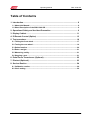
HIGH TECH SECURES YOUR FUTURE
SBA 1200 GB
SUN BRAKE ANALYSER
Operating Manual
Operating Manual
SBA 1200 GB
2
Operating Manual
SBA 1200 GB
Operating Manual
SBA 1200 GB
SUN BRAKE ANALYSER
Copyright December 2009 Snap-on Equipment GmbH
All rights reserved
Part number: 2000618380
Rev: 3
3
Operating Manual
SBA 1200 GB
4
Operating Manual
SBA 1200 GB
DISCLAIMER OF WARRANTIES
AND LIMITATIONS OF LIABILITIES
Whilst the authors have taken due care in the preparation of this manual, nothing
contained herein:
modifies or alters in any way the standard terms and conditions of the purchase,
lease or rental agreement under the terms of which the equipment to which this
manual relates was acquired,
increases in any way the liability to the customer or to third parties.
TO THE READER
Whilst every effort has been made to ensure that the information contained in this
manual is correct, complete and up-to date, the right to change any part of this
document at any time without prior notice is reserved.
Before installing, maintaining or operating this unit,
please read this manual carefully, paying extra
attention to the safety warnings and precautions.
Snap-on Diagnostics
Unit 17 Denney Road
PE30 4HG Kings Lynn
Great Britain
Tel: +44 / (0) 1553-697296
Fax: +44 / (0) 1553-767992
5
Operating Manual
SBA 1200 GB
6
Operating Manual
SBA 1200 GB
Table of Contents
1. Introduction........................................................................................................... 8
1.1 About this Manual ...................................................................................................... 8
1.2 Short Description of the SBA 1200 GB ..................................................................... 8
2. Operational Safety and Accident Prevention ..................................................... 9
3. Display Cabinet ................................................................................................... 11
4. IR Remote Control (Option) ............................................................................... 13
5. Test procedure.................................................................................................... 16
5.1 Testing the front wheel .............................................................................................17
5.2 Testing the rear wheel...............................................................................................19
5.3 Delete function ..........................................................................................................20
5.4 Enter a weight............................................................................................................21
5.5 Measuring ovality ......................................................................................................21
5.6 Stopping a test ..........................................................................................................21
6. Pedal Force Transducers (Optional) ................................................................. 22
7. Printout (Optional) .............................................................................................. 23
8. Service-Routine .................................................................................................. 24
8.1 Calibration routine ....................................................................................................26
8.2 Clock setting..............................................................................................................29
7
Operating Manual
SBA 1200 GB
1. Introduction
1.1 About this Manual
Congratulations for buying a Brake Tester SUN SBA 1200 GB.
In the present Operating Manual, you will find detailed information on the routine
work with your brake tester. SUN products speak for themselves by a steady advancement implying, however, that the Operating Manual may not always be updated.
1.2 Short Description of the SBA 1200 GB
Brake Testers of the series SUN SBA 1200 GB allow easy and quick brake testing
for motorcycles. The test stand is particularly designed for the quick diagnosis in
workshops.
Easy operation connected with a quick test run allows time-saving and efficient brake
tests one after the other after a short training period. The standard version of the
brake tester SUN SBA 1200 GB is equipped with the following components:
roller set
display cabinet with electronic control system
The following options are additionally available:
printer
7-digit display
IR remote control
cable operated pedal force transducer, for hand and foot respectively
wireless pedal force transducer for hand and foot respectively
8
Operating Manual
SBA 1200 GB
2. Operational Safety and Accident Prevention
Conscientiously follow the regulations in the Operating Manual in order to
avoid injury to persons and damage to the equipment.
test stand
in
operation
Please mind that during the brake test no one is staying at close
range to the turning rollers.
If possible, secure the test stand area by means of railings and
colour markings on the floor or by danger signs with warning
lamps. CAUTION! BRAKE TEST!
The tester must remain seated on the vehicle during the test
prior to the testing procedure after having checked that no one is
close to the roller set!
If the Brake Tester is installed at the traffic zone of the workshop
or at an area accessible to the public, it is important that the test
stand is covered or equipped with railings if not in use.
Lock the main switch if the brake tester is not in use in order to exclude any unallowable usage.
Safety regulations in operation:
-
No adjustment work with turning rollers!
-
No motor start via the test stand drive!
No parking on roller brake testers, especially neither with the drive axle, nor with
engaged gear or with turned-on ignition since the engine of the vehicle could start
up on initiating the rollers thus risking that the driverless vehicle gets out of control.
The „emergency operation mode“ (key-operated switch) should only be applied
in order to be able to drive a vehicle off the roller set in case of any test stand operating failure.
Withdraw the key for emergency operation from the display cabinet and put it in
safekeeping to prevent any unauthorized use.
On actuating the „automatic operation mode“, the rollers start up as soon as a
vehicle is driven onto the test stand. For this reason, the driver should take the IR
transmitter with him to be able to switch the test stand off in case of emergency.
—
—
—
—
9
Operating Manual
SBA 1200 GB
The Brake Tester may only be operated within the rated power and the maximum
speed stated in the Technical Data Sheet. Shift period for the rated power is 20%
meaning a two minutes´ operating time is followed by a rest period of 8 minutes.
Slowly drive the vehicle onto the test stand thus avoiding unnecessary strain to
both the vehicle and the test stand.
From time to time check the fastening screws of the cover plates
on their tight fit in order to avoid any tyre damage when driving
onto and off the test stand.
The access to electrical control devices, such as the exchange of
safety fuses not controllable from outside, is only allowed to
skilled workers.
Prior to opening the switch cabinet, disconnect the system from
the mains supply.
Keep dry all parts of the electric system!
Check the safety devices of the brake tester, in particular the
initiators and safety rollers, in regular intervals on their perfect
functioning. Step-in safety devices between the test rollers are
obligatory.
10
Operating Manual
SBA 1200 GB
3. Display Cabinet
Actual measured brake force
wheel
Information rear wheel
Information front
Weight / PD
Switch on indication
Ready indication
Measuring direction
Automatic mode
Manuel mode
11
Operating Manual
SBA 1200 GB
Meaning of the individual operating elements:
Lamps:
ON
Measuring direction
Automatic
Manual
Buttons:
Auto off
Auto on
Cal.
Indicates that the test stand is switched on
and ready to use
Indicates the measuring direction
Indicates that the test stand is working in automatic
mode
Indicates that the test stand is working in manual
mode
Deletes automatic mode if no vehicle is in the roller
set
Switches off a test
Activates the automatic mode.
Starts a test one time
Only required for service / fault finding
12
Operating Manual
SBA 1200 GB
4. IR Remote Control (Option)
The use of the IR remote control allows you comfortable test stand control.
keys 1 – 3
keys 4 – 6
keys 7 – 9
keys 10 – 12
Key 1
Start the input of the test weight
In case of weight input or figure input, this key stands for „7“.
End the input by key 12.
Key 2
Start the input of the total weight.
In case of weight input or figure input, this key stands for „8“.
End the input by key 12.
Key 3
Delete data.
For this purpose, it is important to actuate this key twice within 5 seconds.
Only then all data are deleted and the automatic operation mode set on axle 1
and front axle respectively.
In case of weight input or figure input, this key stands for „9.
13
Operating Manual
SBA 1200 GB
Key 4
Switch between front and rear wheel.
In case of weight input or figure input, this key stands for „4“.
Key 5
Switching between front – rear wheel.
In case of weight input or figure input, this key stands for „5“.
Key 6
Print out.
The stored data are printed.
In case of weight input or figure input, this key stands for „6“.
Key 7
Stopping the roller set
STOP a running measurement.
Switch OFF automatic operation mode if the two starting switches are in UP
position.
In case of weight input or figure input, this key stands for „1“.
Key 8
Switch on automatic mode, start and store a measurement.
Test of one wheel as a service brake with automatic storing of actual axle
number after ending the test.
Switch ON automatic operation mode if the two starting switches are in UP
position.
In case of weight input or figure input, this key stands for „2“.
Key 9
Stopping the roller set
STOP a running measurement.
Switch OFF automatic operation mode if the two starting switches are in UP
position.
In case of weight input or figure input, this key stands for „1“.
Key 10
Start a measurement without store a measurement.
In case of weight input or figure input, this key stands for „0“.
14
Operating Manual
SBA 1200 GB
Key 11
Start ovality measurement.
The ovality measurement is activated by pressing this key during a running
brake test
Key 12
Confirm the input.
In case of weight input or figure input: finish and store input
15
Operating Manual
SBA 1200 GB
5. Test procedure
In order to ensure a smooth test sequence, please proceed as follows:
Switch on the test stand using the main switch. Make sure that no vehicle is in the
test stand.
The test stand is ready for operation after the lamps have ceased flashing.
There are two possibilities of starting the brake test.
Using the remote control (primary control).
Using the buttons on the side if the unit (secondary controls).
Automatic mode is not to be used in the UK.
When performing a brake test as part of a MOT procedure, always refer to the
MOT operator manual for specific requirements, a copy of the manual can be
found at www.motinfo.gov.uk.
When performing a brake test it is recommended that unless using the printer option, results are manually recored after each brake is completed.
When testing a motorcycle with linked brakes or a sidecar with brakes, the overall
brake efficiency should be calculated by the operator.
The brake efficiency for each system is the total of the brake forces achieved by
operating the brake control divided by the total weight of the motorcycle, rider
and sidecar if fitted.
The following description of the test procedure is for manual mode via remote
control.
16
Operating Manual
SBA 1200 GB
5.1 Testing the front wheel
Before entering the roller set the display for the front wheel is flashing and is ready
for a test.
Rear wheel
Front wheel
Drive onto the test stand with the front wheel.
Provided a weighing unit is installed, the wheel weight is now indicated.
Wheel weight front wheel
After pressing the key
the rollers start up after a short waiting period. Do not
brake as long as the lamps are flashing at the display cabinet.
If the lamps have ceased flashing and no brake is applied, the rolling resistance is
shown on the needle. Now it is possible to brake slowly and regularly up to wheel
block. If a pedal sensor is used the measured value is shown on the display instead
of the wheel weight.
Efficiency front wheel
Wheel weight and /or
pedal force when a sensor is used
17
Operating Manual
SBA 1200 GB
Directly after the roller set has stopped the kind of stop is shown on the display.
There are 3 different kinds of stop:
LL = wheel has locked, FF = brake force reduction, PP = wheel was lifted out
Kind of stop front wheel
5 seconds after the roller set has stopped the efficiency of the wheel is shown on the display.
This efficiency is calculated after the wheel weight.
Efficiency front wheel
Wheel weight
ATTENTION:
If the test time is too short the display shows
And the test should be repeated.
Now the test for the front wheel is finished and the rear wheel can be tested.
18
Operating Manual
SBA 1200 GB
5.2 Testing the rear wheel
Before entering the roller set the display for the rear wheel is flashing and is ready for
a test.
Rear wheel
Efficiency front wheel
Drive onto the test stand with the rear wheel.
Provided a weighing unit is installed, the wheel weight is now indicated.
Efficiency front wheel
Wheel weight rear axle
After pressing the key the rollers start up after a short waiting period. Do not brake
as long as the lamps are flashing at the display cabinet.
If the lamps have ceased flashing and no brake is applied, the rolling resistance is
shown. Now it is possible to brake slowly and regularly up to wheel block. If a pedal
sensor is used the measured value is shown on the display instead of the wheel
weight.
Efficiency front wheel
Wheel weight and /or
pedal force when a sensor is used
19
Operating Manual
SBA 1200 GB
Directly after the roller set has stopped the kind of stop is shown on the display.
There are 3 different kinds of stop:
LL = wheel has locked, FF = brake force reduction, PP = wheel was lifted out
Kind of stop rear wheel
5 seconds after the roller set has stopped the efficiencies of the wheels are shown on the
display. These efficiencies are calculated after the total weight.
Efficiency rear wheel Efficiency front wheel
Total weight
This result is shown on the display as long as the memory is deleted.
5.3 Delete function
The memory should be deleted before a new test is started.
After the delete key is pressed the display is showing “ccc” and the needle for the
brake force is going to half of scale.
Now the delete key
must be pressed again within 3 seconds. Only then the deletion is performed. As a confirmation the display shows “CCC” and the needle for the
brake force is going to end of scale.
20
Operating Manual
SBA 1200 GB
5.4 Enter a weight
If there is no weighing unit available the weight must be input manually. Otherwise no
efficiency can be calculated.
To start the input the button
or . As a confirmation all lamps on the display cabinet are flashing. Now the buttons with the blue numbering are used to input the
weight. To confirm the weight the button
has to be pressed.
After a complete test the axle deceleration of the front and rear wheel is shown on
the display.
5.5 Measuring ovality
The ovality can be tested at any time during a brake test.
To start the measuring hold the brake force constantly and press the button . As a
confirmation the both lamps for the measuring direction are flashing. During this time
the brake force must be constantly. When the lamps are off again the brake test can
be continued.
It is recommended to perform the ovality test above 2/3 of the expected brake force.
5.6 Stopping a test
With the key
the roller set can be switched off at any time. With this key also the
automatic function can be deleted.
21
Operating Manual
SBA 1200 GB
6. Pedal Force Transducers (Optional)
In order to be able to measure the required operating force of the brake, pedal force
transducers are used. Because of the different constructions of the brake handles of
motorcycles, there are different versions.
The pedal force transducers are connected to the sleeves on the left-hand bottom
side of the display cabinet.
PD 7 foot force transducer
PD 8 hand force transducer
PD 6 (wireless)
force transducer for foot and hand in a set
22
Operating Manual
SBA 1200 GB
7. Printout (Optional)
23
Operating Manual
SBA 1200 GB
8. Service-Routine
In case the SBA 1200 GB fails to function correctly, it is possible to obtain a simple
and quick error diagnosis by means of the built-in service routine.
For calling in the service routine, keep depressed the "AUTO OFF" tip switch at the
display cabinet and simultaneously switch on the main switch of the test stand. It is
important to keep the "AUTO OFF" tip switch depressed until number 1 is indicated
on the display signalling that the test stand is in the first step of the service routine.
The number of the actual test step including the respective measured value of the
transducer and/or sensor in mA is indicated at the display each. The pointer of the
indication shows always about half the value of the current.
The change from one test step to the next one is possible by pressing the „Stop“ key
at the display cabinet or on the remote control
Sequence:
step
meaning
automatic lamp
manual lamp
1
Brake force
flashes
off
2
Weighing unit front left
off
flashes
3
Weighing unit front right
flashes
flashes
4
Weighing unit rear
on
off
5
Pedal force 500N
off
on
6
Pedal force 1000N
on
on
7
Slip sensor
flashes
on
8
Position sensor
on
flashes
9
Selection :
off
off
clock setting
or AUTO OFF :calibration routine
24
Operating Manual
SBA 1200 GB
Zero points:
step
1
meaning
display
Brake force (1 direction tester)
OR
~ 1.00 mA
pointer
~ 20 kgF
~ 200 N
OR
1
Brake force (2 direction tester)
~ 5.00 mA
2
Weighting unit front left
~ 1.00 mA
3
Weighting unit front right
~ 1.00 mA
4
Weighting unit rear
~ 1.00 mA
5
Pedal force 500 N
~ 1.50 mA
6
Pedal force 1000 N
~ 1.50 mA
7
Slip sensor
0.00 or 8.00 mA
8
Position sensor
0.00 or 8.00 mA
~ 95 kgF
~ 950 N
~ 20 kgF
~ 200 N
~ 20 kgF
~ 200 N
~ 20 kgF
~ 200 N
~ 30 kgF
~ 300 N
~ 30 kgF
~ 300 N
0 - 300 kgF
0 - 3000 N
0 - 300 kgF
0 - 3000 N
Active calibration check:
step
1
meaning
Display
Brake force (1 direction tester)
OR
~ zeropint + 8.00 mA
OR
1
Brake force (2 direction tester)
~ zeropint + 4.00 mA
2
Weighting unit front left
~ zeropint + 8.00 mA
3
Weighting unit front right
~ zeropint + 8.00 mA
4
Weighting unit rear
~ zeropint + 8.00 mA
5
Pedal force 500 N
~ zeropint + 8.00 mA
6
Pedal force 1000 N
~ zeropint + 8.00 mA
Slip sensor
no calibration check
Position sensor
no calibration check
7
8
pointer
~ zeropoint + 150 kgF
~ zeropoint + 1500 N
~ zeropoint + 150 kgF
~ zeropoint + 1500 N
~ zeropoint + 150 kgF
~ zeropoint + 1500 N
~ zeropoint + 150 kgF
~ zeropoint + 1500 N
~ zeropoint + 150 kgF
~ zeropoint + 1500 N
~ zeropoint + 150 kgF
~ zeropoint + 1500 N
~ zeropoint + 150 kgF
~ zeropoint + 1500 N
25
Operating Manual
SBA 1200 GB
8.1 Calibration routine
For calling in the calibration routine, press the button
or the “AUTO ON” button at step „9“ in the service routine".
Operation:
Next step
Last step
Close the calibration routine and go back to the service routine
Print the adjustments
Call up the number insert
Delete the last input digit
26
Operating Manual
SBA 1200 GB
Sequence:
step
meaning
value
automatic lamp
manual lamp
1
Brake force
3000 N
flashes
off
2
Weighing unit
500 kg
off
flashes
3
Pedal force 500N
50 kg
flashes
flashes
4
Pedal force 1000N
100 kg
on
off
5
No function
off
off
6
No function
off
off
7
Legal value total efficiency
off
off
8
Legal value front efficiency
off
off
9
Legal value ovality front
off
off
10
Legal value pedal force front
off
off
11
No function
off
off
12
Legal value rear efficiency
off
off
13
Legal value ovality rear
off
off
14
Legal value pedal force rear
off
off
15
Inner scale
3.00
off
off
16
Outer scale
3.00
off
off
17
Calibration value brake force
7860
off
off
(3000: 2 directions, 7860: 1 direction)
18
Calibration value weighing unit
500
off
off
19
Calibration value pedal force
50
off
off
20
Calibration value pedal force
100
off
off
21
Stepper
356
off
off
22
IR code
3
off
off
23
Printout kgf
255
off
off
off
off
(kgf = 255, N = 0)
24
No function
25
Min. brake force for drive out function
0
off
off
26
Slip value
27
off
off
27
2 measuring directions
0
off
off
(YES = 255, NO = 0)
28
Calculation factor
100
off
off
29
Min. brake time for storing in 1/10 s
10
off
off
30
Automatic function allowed
128
off
off
0
off
off
(YES = 255, NO at switch on = 128, NO = 0)
31
Switch off at brake force reduction
27
Operating Manual
SBA 1200 GB
(YES = 255, NO = 0)
32
Duration of ovality measurement in 1/10 s
30
off
off
33
Duration of turn on again in 1/10 s
40
off
off
34
Warning time before turn on in 1/10 s
10
off
off
35
Display time in 1/10 s
50
off
off
36
Show kind of slip on display
255
off
off
0
off
off
0
off
off
(YES = 255, NO = 0)
37
Show last brake forces
(NO = 255, VES = 0)
38
Print automatically after test end
(YES = 255, NO = 0)
39
Time of RPM control after start in 1/10 s
15
off
off
40
RPM value after switch on
240
off
off
41
No function
off
off
42
No function
off
off
43
No function
off
off
44
No function
off
off
45
No function
off
off
46
No function
off
off
47
No function
off
off
NOTE:
ANY CHANGE OF THE SETTINGS ABOVE ARE ON OWN RISK!
28
Operating Manual
SBA 1200 GB
8.2 Clock setting
For calling in the clock setting routine, press the button
at step „9“ in the service routine".
The clock setting routine need to be equipped with the IR remote control!
In the clock setting routine set the clock built in the unit. Enter all inputs in the following order:
hour - decimal
hour – units digit
minute - decimal
minute – units digit
day - decimal
day – units digit
month - decimal
month – units digit
year - decimal
year – units digit
In doing so, it is important always to enter leading zeroes.
Meaning
Example for the input
hour: ten-figure
1
hour: one-figure
12
minute: ten-figure
121
minute: one-figure
1217
day: ten-figure
12171
day: one-figure
121710
month: zero-figure
1217101
month: one-figure
12171001
year: ten-figure
1217100120
year: nine-figure
121710012009
time/date
12:17, 10.01.2009
store the input and go back to the service routine
If a printer is connected, each data entry is likewise output by the printer. After entering the last figure, complete the input of time and date by actuating the "Enter" key on
the remote control. In order to quit the service routine, switch off the main switch.
29
Operating Manual
SBA 1200 GB
Änderungsvorgänge:
März 2009/ET – Version 1.0:
Anleitung erstellt.
07.05.09/PL-mw – Version 2.0:
Punkt 8 – Serviceroutine ergänzt.
27.11.09/IS:
CE-Erklärung entfernt, Dateiname geändert
10.12.09/Julian Woods – Version 3.0:
Punkt 5 – Test procedure überarbeitet.
30