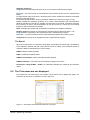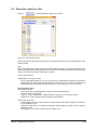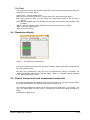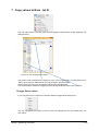
1
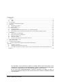
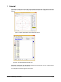
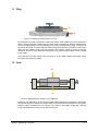
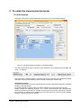
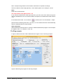
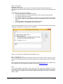
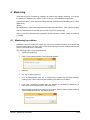
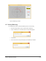
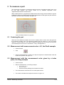
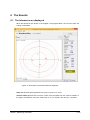
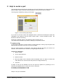
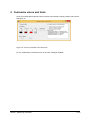
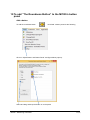
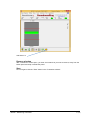
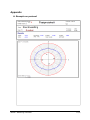
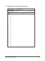
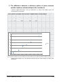
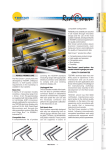
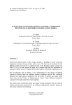
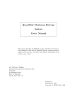
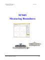
Matematikföretaget jz 150702/SJn www.M7005.metem.se M7005 Measuring Roundness M7005 – Measuring roundness 1 (24) Contends 1 General ..................................................................................................................................................... 3 1.1 Ring .................................................................................................................................................. 4 1.2 Axel .................................................................................................................................................. 4 2 To get started ............................................................................................................................................ 5 3 To setup the measurement program............................................................................................................ 7 4 Mastering ................................................................................................................................................ 10 4.1 Mastering by rotation ....................................................................................................................... 10 4.2 Ordinary Mastering.......................................................................................................................... 11 5 To measure a part .................................................................................................................................... 12 5.1 Centering the part ............................................................................................................................ 12 5.2 Measurement with measurement order = H1, the Shaft example ....................................................... 12 5.3 Measurement with the measurement order given by a index pulse, the Ring-example........................ 12 6 The Results ............................................................................................................................................. 13 6.1 The tolerances are displayed ............................................................................................................ 13 6.2 The Tolerances are not displayed ..................................................................................................... 14 6.3 Show the result as a list.................................................................................................................... 15 6.4 Dimension display ........................................................................................................................... 16 6.5 Print of test protocol and measurement values list............................................................................. 16 7 Copy values to/from .txt fil ..................................................................................................................... 17 8 Help to center a part ................................................................................................................................ 18 9 Customize colors and fonts ...................................................................................................................... 19 10 To add ”The Roundness Button” to the M7005’s button panel .............................................................. 20 Appendix ........................................................................................................................................................ 22 A. Example on protocol ........................................................................................................................ 22 B. Example on a measurement values list ............................................................................................. 23 C. The difference between a reference sphere of glass centrum and the rotation centrum influence the roundness.................................................................................................................................................... 24 The information in this document is subject to changes without notice and should not be construed as a commitment by Matematikföretaget jz (Sverker Johansson) Matematikföretaget jz assumes no responsibility for any errors that may appear in this document. On no event shall Matematikföretaget jz (Sverker Johansson) be liable for direct or consequential damages arising from use of this document or by software or hardware described in this document. M7005 – Measuring roundness 2 (24) 1 General The program measures the radius of a rotating detail during one lap. The result is presented graphically, see Figure 1. The underlying measurement values are displayed as a list, see Figure 2. Figure 1 Graphic presentation of measurement results. Figure 2. The measurement result as a list. Description of the M7005, see the Manual: M7005 User manual witch and can be downloaded from M7005 's website M7005. metem.se. Two examples are used throughout this manual: M7005 – Measuring roundness 3 (24) 1.1 Ring T1 I2 Index Figure 3. Roundness measurement of a ring We measure a ring that is posted on a table that rotates. On the table is an index mark and a sensor (I2) that provides a pulse when the index mark is passed. By allowing measurement order to be high between two index passages, we retrieve readings during a lap. The ring must be positioned so that T1 works within its working range throughout the revolution, but the ring's center and the rotation center need not coincide. The program is able to correct for a minor difference. About 4% of the differences between the ring center and the rotation center is added to the ovality. Note However, the table center must not throw. If so the table centrum movement will be included in the measured ovality. 1.2 Axel T2 T1 Figure 4. Measurement of ovality for one diameter. Unlike the ring example we do not have an index pulse to start/stop the measuring, instead we must let the program, based on the rotation speed, calculate how long a lap takes. The program begins to take in readings when we click the "run" button in the graphic image and continues to the estimated time to rotate one revolution has gone. M7005 – Measuring roundness 4 (24) 2 To get started Give the required roundness parameters In the measurement program you must declare the measurement as a roundness measurement. You must also specify the rotation rate, sample rate, and if the measurement program shall be mastered by rotation. See section 3: To setup the measurement program To show the roundness measurement form The image in Figure 1 is displayed by M7005 's drop-down menu "Applications/Roundness measurement". The picture has its own button that you can put out on the M7005’s button panel by "Tools/Adjust Status- and Button Panel”. Mastering If you only are interested in the ovality, i.e. the difference between the maximum and minimum radius, there is no need for mastering and there no use of tolerances. On the other hand, if you like to know the measurements absolute value, you must, as always, do a mastering. Mastering can be done in two ways, either by having a reference ring rotate one revolution (mastering by rotation), or by putting a master between the center of rotation and the transducer (regular mastering). More information in part 4 Mastering. Measuring Place the part in the measuring position. For the ring example, the ring has to be centered. In order to make it easier there is a window "Help to center a part" see section 8. The radius in the shaft example is measured by two opposite transducers and in this case there is no need for centering. Note: The centering does not have to be absolute since the program compensates for differences between the tables rotation center and the center of the part. However this discrepancy must not get too big, when about 4% of the deviation enters in the ovality. See Appendix C. The measurement starts in the ring example by the index pulse and continues to the next index pulse. For the shaft example, the measurement starts when you click on "run" button and continues until the time a lap is expected to take has run out. M7005 – Measuring roundness 5 (24) The result The results are displayed as a graph and the various radius calculated in the "Results" see Figure 1. The individual measurement values can be seen in the image that is displayed if you click on the button "As List" see Figure 2. If you like the result may be saved to a .txt file. You can also retrieve previously saved measurements from .txt files. See section 7 M7005 – Measuring roundness 6 (24) 3 To setup the measurement program The Shaft example The figure 5 shows the ”Define Measurement Programs” form for the Shaft example. Figure 5. The measurement program for the Shaft example The input “Roundness” below is shown if any dimension in the measurement program has mode = roundness. Here specifies the rotation speed in revolutions per minute, how often the program will request values per second and if mastering is to be made by rotating the master a lap. Samplings frequency For high sample rates (more than 5 times/sec) there will be a difference between the desired frequency and what we get. It’s because Windows has a minimum resolution between two time events (type 16 ms). M7005 translate the sampling frequency in to a time interval between two measurements. Windows remake the interval to a multiple of its minimum time interval. If Windows minimum time interval is 16 ms its second smallest is 32 ms next 48 ms etc. That is why the resulting frequency often is less than the desired. M7005 – Measuring roundness 7 (24) Note: A sample rate greater than 35 times/sec is Windows not capable to manage. The time it takes to rotate a lap (lap time) = 1/the rotation speed. In the example = 30 sec. Mode Mode has to be Roundness The measurement order (Meas.Order) = H1 If you want the measurement order to go high when you click on the "Run" button and go low after the estimated time as one revolution takes has expired, the measurement order must be = H1. If the measurement order = H1 the button will be shown in the “Roundness – Graph” picture and the measuring start when you click on it. The measurement then exit automatically when the estimated time for a lap has past. Other parameters Other parameters will be set as for a "common" M7005 measurement program. In the example, the register order = I2, Tolerance +-0.05. etc. The Ring example In Figure 6 below shows the "Define Measurement Program" form for the Ring example. Figure 6. Measuring the program for the Ring example. M7005 – Measuring roundness 8 (24) Mode = Roundness Registration order = I8. Furthermore, we assume that we have a button (Start measurement) that affect the I7. The rotation table has an index mark that gives a short pulse on I2 every time mark passes the sensor. Measurement of a ring can then look like The part is placed on the table and centered The operator presses the “Start measurement” button to start the measurement. The operator starts the revolution The table and detail must have time to accelerate up to steady speed so we let table spin at least 2 laps (two index passages shall be detected before the measurement starts). The measurement order goes high at the third index pulse The measurement is completed by fourth index pulse. We fix it with a plc program. Click on "Edit Plc Program" from the menu and the form in Figure 7 appears. We input the code as shown in the picture Figure 7. PLC program to generate the measurement order. H11 = counter(I7, I2, 3, 1) When I7 goes high the counter is activated so when I2 goes high the counter counts up a step. When the I2 goes high the third time, the H11 goes high. H11 remains high until the next pulse of I2. How to program M7005: plc-function are described in the Manual: M7005 – Plc programming. The manual can be downloaded from M7005 's home page M7005.metem.se Note: In the usual “Display Dimension” picture the values are continuous updated as long as measurement order is high. When the measurement is completed (measurement order goes low) the results is calculated and roundness measurements shows the ovality (roundness = RMax – RMin) M7005 – Measuring roundness 9 (24) 4 Mastering There are two types of mastering, mastering by rotation and ordinary mastering. You choose the type by the "Mastering by rotation" when you put up your measurement programs. A measured value = (the numerical value that the measurement formula gives) + (zero difference) Where Zero difference = (The measured deviation from nominal value) – (the numerical value that the measurement formula gives at the time of the mastering) Note. If you are only interested in the parts form and its roundness = RMax – RMin no mastering is needed. 4.1 Mastering by rotation Mastering is done by rotating the master ring. During the revolution all values are collected and forms the mean value. The mean value is used as the value given by the measurement formula when the zero difference is calculated.. The mastering is like a normal measurement. Center the master ring Click on the mastering button. The sign below appears Click OK The sign in figure 8 pops up. If H1 is measurement order (i.e. a measurement program like the shaft example), clicking on the "Start" button and the mastering proceeds one revolution. If we have a measuring program type ring example, the mastering is started by an index pulse, and continues to the next index pulse When mastering has proceed a full turn you click the "Return" button and the mastering window disappears and the sign below pops up M7005 – Measuring roundness 10 (24) Figure 8. Mastering by rotation 4.2 Ordinary Mastering If not "Mastering by rotation" is selected. Mastering is done in the usual way Place the master between center of rotation and the transducer Click on mastering icon on the button panel. The sign below appears Click OM OK After a few seconds, the sign below pops up and mastering is complete. M7005 – Measuring roundness 11 (24) 5 To measure a part The requirement for making a roundness measure is that the ”Roundness Graph" figure 10 is the top most window. The picture comes up by M7005’s drop-down menu "Applications/Roundness measurement". While measurement is in progress (the measurement order is high) and the window in figure 9 is displayed. When the measurement is finished (measurement order goes low) the window is shut down, and the result is reported, see figure 10. Figure 9. Measurement is in progress. 5.1 Centering the part About 4% of the difference between the center of rotation and the center of the part goes into the roundness (ovality) value. The difference between the two centers is = root of ((Center offset X)2 + (center offset Y)2). Let's say the difference between the two centers is 20 my then one should expect an error in the roundness < 0.8 my. See appendix C. . 5.2 Measurement with measurement order = H1, the Shaft example Center the part Click After the estimated time of rotating one lap has expired, the measurement ends and results are reported, see figure 10. 5.3 Measurement with the measurement order given by a index pulse, the Ring-example Center the part Start the measurement. In the Ring example o Give a pulse on I7 o Start the rotation o At the third index passage the measurement starts. The measurement ends when the next index pulse arrives The result is calculated and reported, as shown in figure 10. M7005 – Measuring roundness 12 (24) 6 The Results 6.1 The tolerances are displayed When the tolerances are shown in the diagram, the program takes it into account when the scaling is calculated. Figure 10. Roundness result with tolerances displayed Scale specifies the spacing between two rings, in figure 10 is 10 my. Centrum offset specifies how much the center of the part differ from the center of rotation. In the figure, the deviation of the two centers are 11 my in x direction and 20 my in y direction M7005 – Measuring roundness 13 (24) Sampling Frequency Programed is that sampling rate given when you put up the measurement program. Received = the total number of measurement values divided by the time the measurement lasted. For high sample rates (more than 5 times/sec) there will be a difference between the desired frequency and what we get. It’s because Windows has a minimum resolution between two time events (type 16 ms). M7005 translate the sampling frequency in to a time interval between two measurements. Windows remake the interval to a multiple of its minimum time interval. If Windows minimum time interval is 16 ms it’s second smallest is 32 ms next 48 ms etc. That is why the resulting frequency often is less than the desired. Note: A sample rate greater than 35 times/sec is Windows not capable to manage. Rotation speed (not shown for measurement programs with measurement order = H1) Programmed It is specified in the programming of the measurement program. Received = 1 / the time between the two index pulses that started and ended the test. Tolerances they are given at programming of the measurement program. The Result When the measurement is completed, the program recalculates the values with consideration of the difference between the part center and the center of rotation (the coordinate system is moved the distance specified by the Center offset) R-Max = largest measured radius R-Min = smallest measured radius R-Mean least squares =radius calculated by least-squares R-Mean arithmetic = The radius as the arithmetic average of all values Roundness, ovality (R-Max - R-Min) = the difference between the maximum and minimum radius. 6.2 The Tolerances are not displayed If the tolerances not to be shown, the program use the entire area to display the graph. The resolution will now be 5 my instead of 10 my in figure 10. Figure 11. Roundness measurement tolerances not shown M7005 – Measuring roundness 14 (24) 6.3 Show the result as a list Click on and the window in figure 12 is shown. Figure 12. The numeric values The list shows the individual measurement values (radius) after they are compensated for the centrum offset. Note When the measurement order goes high the data buffer is cleared. The previous measurement values of the previous measurement are lost. If you want to save the measured values you may doing it as a text file using the "File/Copy to .txt file". # is the serial number. "Select Meas. For Copy or Print" As for other table Windows, you can choose which measurement values to be printed or copied, either by clicking the up/down arrows for "From" and "To", or use the mouse. Press and hold the left mouse button pressed while you move the pointer in the "#" column. The drop down menu "File" has the choice "Print" prints the in "Select Meas. for Copy or Print" selected values. "Preview" and "Printer setup" "Copy to .txt file." copies the in "Select Meas. for Copy or Print" selected values. "Read from .txt file" will bring back previously saved values. "Show" has the choice "Page Header". Here you can choose if you want the box with "Name", "Batch" and "Show", to be displayed or not "Select for Copy/ Print". You select if the panel "Select Meas. for Copy or Print" shall be displayed or not. "Show options", if the box "Show" shall be visible or not. M7005 – Measuring roundness 15 (24) The Table The measurement values are reported in table form. The outlook of the table is defined by the checkboxes in the “Show” panel. PopUp menu – Change/ Delete values Right-click in first column (# column), a popup menu which has the following options ”Edit”. After clicking on “Edit”, you can change the measurement values in the row that is selected. ”Save” Are you satisfied with your changes and want them to be saved in the data base, click on "Save" ”Delete”. You can delete an entire measurement (whole row) by using the "Delete". ”Back” removes the popup menu. ”Help” This text shows up. 6.4 Dimension display Figure 13. The Dimension Display picture As long as measurement order is high “Dimension Display” display values as the measurement formulas calculates them. But when the measurement goes low and the measurement result is calculated, the “Dimensions Display” bars shows roundness, RMax – RMin. I.e. the same value as displayed in the “Roundness Graph” image. 6.5 Print of test protocol and measurement values list By roundness measurement's graphic image drop-down menu, you can print a protocol from the current measurement. An example can be found in Appendix A The individual measurement values can be printed from the "Roundness – List” image". You can in the “Select Meas. for Copy or Print” , choose which values to be printed. See figure 14 below. Example are in Appendix B. M7005 – Measuring roundness 16 (24) 7 Copy values to/from .txt fil You can copy to/from a text file, both from the graphic image and the image displaying the values as a list. Figure 14. The measurement values You have to mark “Selection for Copy/Print” in the “List” images (figure 14) drop down menu “Show” other wise the “Select Meas. for Copy and print” panel is hidden. Sets the From and To inputs to start/end values to be printed/copied, You can also select values by dragging with the left mouse button down in the # column. Change, Delete values If you right click on the number for a specific value the image below will pops up. You can change/remove values on the line. Are the changes OK, they are saved when you click "Save". M7005 – Measuring roundness 17 (24) 8 Help to center a part The program has a window (Figure 15) that you can use as help when you center the part. The goal is to get the parts center as close as possible (< 50 my) to the center of rotation. You bring up the window by clicking on the button Figure 15. The centering help image. If you click on the "Zero" button the displayed value is reset and all subsequent values are calculated on the basis on the zero value. Shown value = current transducer value - the transducer value at the zeroing. Clicking the “Absolute” button, the transducer value is shown as it is. You choose witch transducer you want to display by the up/down arrows. To center a ring An appropriate approach to center the part, as in Ring-example, is after you put the part on the table as near the center as you can, to do it in two steps. First you center the part in one direction, here called X direction and then you center it in a direction, here referred to the Y direction, at a right angel from the first. Centering in X direction 1. Zero the output 2. Turn the part a half turn. 3. Notice the value 4. Move the detail in the X direction half the indicated value. On Figure 15 shows the value after the turn we must move the part so the image shows 8 my. 5. Jump till 1 So keep on until you are satisfied, then turn the part one quarter turn (centering in the Y direction) and repeat points 1 to 5 but now for the Y direction. If necessary re do the position in X led. If necessary re do the position in Y led. . . Keep on until you are satisfied. M7005 – Measuring roundness 18 (24) 9 Customize colors and fonts As for the most M7005 images and forms, there are two default out looks, Classic and Colored. See figure 16. Figure 16. Form to customize colors and fonts. For any modification to be allowed you must check "Changes Enabled". M7005 – Measuring roundness 19 (24) 10 To add ”The Roundness Button” to the M7005’s button panel Add a button To add the roundness button on M7005 's button panel do the following Click on “Adjust Status- and Button Panel” and figure below pops up. Select and drag and drop the button on to the panel M7005 – Measuring roundness 20 (24) And there it is Remove a button With ”Customize” window open, you draw the button that you want to remove, away from the button panel and drop it outside the panel. Save Do not forget to click the "Save" button in the "Customize window". M7005 – Measuring roundness 21 (24) Appendix A. Example on protocol M7005 – Measuring roundness 22 (24) B. Example on a measurement values list Matematikföretaget Name: RoundnessRing UTol: 0.050 LTol: -0.050 #&: Name: Roundness - List Batch: b1 Printed: 15-06-30 13:50:15 Mått: 1-1 Page: 1 M1 Rundhet 1 0.009 2 0.009 3 0.009 4 0.009 5 0.009 6 0.009 7 0.008 8 0.008 9 0.007 10 0.007 11 0.006 12 0.006 13 0.005 14 0.004 15 0.003 16 0.003 17 0.002 18 0.001 19 0.000 20 -0.001 21 -0.001 22 -0.002 23 -0.003 24 -0.004 25 -0.005 26 -0.005 27 -0.006 28 -0.007 29 -0.007 M7005 – Measuring roundness 23 (24) C. The difference between a reference sphere of glass centrum and the rotation centrum influence the roundness. A sphere of glass with ovality = 0,2 my is positioned x,y offset of the rotation center. The roundness is then measured Test på glassfär (orunfhet0,2 my) mha CEJ:s rundhetsmätare Datum:150612 x y -1 10 -3 -3 1 10 13 0 17 25 31 50 centrum dif 0 -18 -6 -6 -11 -18 -28 0 -26 -32 -42 -52 orundhet -0,2 1,00 20,59 6,71 6,71 11,05 20,59 30,87 0,00 31,06 40,61 52,20 72,14 orundhet 0,1 0,6 0,2 0,1 0,44 0,65 1,42 0,12 1,3 1,53 2,01 3,04 0,2 0,3 glassvären är 0,2 my orund 0,8 0,4 0,38 0,64 0,85 1,62 0,32 1,5 1,73 2,21 3,24 3,5 3 2,5 2 Serie1 1,5 1 0,5 0 0,00 10,00 20,00 30,00 40,00 50,00 60,00 70,00 80,00 Results: Approximately 4% of the difference between the two centers enters as a part of the roundness. M7005 – Measuring roundness 24 (24)