1
TECHNICAL REPORT
SUBJECT/TASK (title)
SINTEF Energy Research
Address:
Reception:
Telephone:
Telefax:
NO-7465 Trondheim,
NORWAY
Sem Sælands vei 11
+47 73 59 72 00
+47 73 59 72 50
ELCOM-90 Application Service Element, User's Manual
CONTRIBUTOR(S)
Nils Eggen,
Ingeborg Graabak, Jens Krystad, Tormod Lund
www.energy.sintef.no
CLIENTS(S)
Enterprise No.:
NO 939 350 675 MVA
Joint Project: ABB Kraft AS, Siemens AS,
Sintef Energy Research AS, Statnett SF
TR NO.
DATE
TR A4124.03
2011-02-16
ELECTRONIC FILE CODE
CLIENT’S REF.
PROJECT NO.
12X513
RESPONSIBLE (NAME, SIGN.)
CLASSIFICATION
Ove Grande
Unrestricted
COPIES
ISBN N0.
REPORT TYPE
RESEARCH DIRECTOR (NAME, SIGN)
82-594-2640-4
-
Petter Støa
PAGES
88
DIVISION
LOCATION
LOCAL FAX
Energy Systems
Sem Sælands vei 11
+47 73 59 72 50
RESULT (summary)
This document describes a specific implementation of the ELCOM-90 Service Element, also called the
Reference Version. The Reference Version is available on different Unix and Windows platforms.
The document describes how to manage an ELCOM-90 installation at different platforms. The
Application Programming Interface (necessary to develop User Elements utilizing the ELCOM-90
services) and the operation management of the ELCOM-90 service element are described.
This .03 version of the document is an updated version of the .02 version. The updates are mainly
information regarding the Windows version of the ELCOM-90 Reference Version. Future updates and
new versions will NOT be published for this reason. New versions will only be submitted when technical
changes are made.
Please see SINTEF’s homepage at: http://www.sintef.no/ELCOM-90. From here you can download the
latest version of all relevant documents as pdf-files for free.
Copyright:
Reproduction of this document is prohibited without permission from SINTEF Energy Research
Liability:
Vendors and utilities are free to implement software based on the present specifications, but SINTEF
Energy Research cannot be rendered responsible for any software declared to be in conformity with the
present specifications.
KEYWORDS
SELECTED BY
AUTHOR(S)
Data Communication
Control Centres
Energy management
ELCOM-90
3
TABLE OF CONTENTS
Page
1
Scope................................................................................................................................. 7
1.1
OPERATION MANAGEMENT OF ELCOM-90 SERVICE ELEMENT ............... 7
1.2
USER ELEMENT IMPLEMENTATION GUIDE.................................................. 7
2
INTRODUCTION ............................................................................................................. 8
2.1
ASSOCIATED DOCUMENTS .............................................................................. 8
2.2
HARDWARE PLATFORM AND OPERATING SYSTEMS................................. 9
3
SYSTEM OVERVIEW ................................................................................................... 10
3.1
MAIN MODULES ............................................................................................... 10
4
Installation guide UNIX and linux ................................................................................... 13
5
Installation guide Windows ............................................................................................. 14
5.1
System Requirements ........................................................................................... 14
5.2
Installation Procedure ........................................................................................... 14
5.3
Selectable Components ........................................................................................ 18
5.4
Runtime directory................................................................................................. 18
5.5
Files Installed ....................................................................................................... 19
5.6
Upgrade Procedure ............................................................................................... 20
6
CONFIGURATION ........................................................................................................ 21
6.1
Overview ............................................................................................................. 21
6.2
Configuring for TCP/IP communications ............................................................. 21
6.3
Configuring for TLS communications .................................................................. 21
6.4
Configuration variables defined by the file elc-conf.............................................. 22
6.5
The elc-xcp configuration file ............................................................................... 29
7
Operation and Supervision .............................................................................................. 31
7.1
Windows .............................................................................................................. 31
7.1.1
Starting and stopping the software .......................................................... 31
7.1.2
Using Operating System Tools To Monitor the Software ........................ 31
7.1.3
Using Other Tools .................................................................................. 31
7.2
Unix ..................................................................................................................... 32
8
ADDRESSING................................................................................................................ 32
8.1
Addressing ........................................................................................................... 32
9
Programming for TLS...................................................................................................... 33
9.1
Encoding of the security information field for TLS............................................... 34
9.2
Certificate handling in the initiator ....................................................................... 34
9.3
Certificate handling in the responder .................................................................... 34
10
Service Interface Procedures when called from C ............................................................ 36
10.1 INITIATION........................................................................................................ 37
10.1.1 ainit ........................................................................................................ 37
10.2 ATTACHMENT AND DETACHMENT PROCEDURES ................................... 38
10.2.1 aatt ......................................................................................................... 38
ELCOM-90 Application Service Element User’s Manual, TR A4124.03
February 2011
4
10.3
10.4
10.5
10.6
10.7
10.8
10.9
10.2.2 adet ........................................................................................................ 38
CONNECTION ESTABLISHMENT PROCEDURES ......................................... 39
10.3.1 aconrq .................................................................................................... 39
10.3.2 aconi....................................................................................................... 39
10.3.3 aconrs ..................................................................................................... 40
10.3.4 aconc ...................................................................................................... 40
CONNECTION TERMINATION PROCEDURES .............................................. 41
10.4.1 arelrq ...................................................................................................... 41
10.4.2 areli ........................................................................................................ 41
10.4.3 arelrs ...................................................................................................... 41
10.4.4 arelc ....................................................................................................... 42
10.4.5 apabt....................................................................................................... 42
GROUP MANAGEMENT ................................................................................... 43
10.5.1 agmrq ..................................................................................................... 43
10.5.2 agmi ....................................................................................................... 43
10.5.3 agmrs ..................................................................................................... 44
10.5.4 agmc....................................................................................................... 44
GROUP DEFINITION......................................................................................... 45
10.6.1 adgrq ...................................................................................................... 45
10.6.2 adgi ........................................................................................................ 45
10.6.3 adgrs....................................................................................................... 46
10.6.4 adgc........................................................................................................ 46
READOUT OF GROUP DEFINITION ............................................................... 47
10.7.1 aggrq ...................................................................................................... 47
10.7.2 aggi ........................................................................................................ 47
10.7.3 aggrs....................................................................................................... 48
10.7.4 aggc........................................................................................................ 48
INFORMATION TRANSFER ............................................................................. 49
10.8.1 aitrq ........................................................................................................ 49
10.8.2 aiti .......................................................................................................... 49
10.8.3 adtrq ....................................................................................................... 50
10.8.4 adti ......................................................................................................... 50
10.8.5 acdrq ...................................................................................................... 51
10.8.6 acdi ........................................................................................................ 51
10.8.7 asmrq ..................................................................................................... 51
10.8.8 asmi........................................................................................................ 52
10.8.9 asmrs ...................................................................................................... 52
10.8.10 asmc ....................................................................................................... 52
10.8.11 actrq ....................................................................................................... 53
10.8.12 acti ......................................................................................................... 53
10.8.13 actrs........................................................................................................ 54
10.8.14 actc......................................................................................................... 54
10.8.15 amdrq ..................................................................................................... 55
10.8.16 amdi ....................................................................................................... 55
10.8.17 amderq ................................................................................................... 55
10.8.18 amdei ..................................................................................................... 56
TEST CONNECTION ......................................................................................... 56
10.9.1 atcrq ....................................................................................................... 56
10.9.2 atci ......................................................................................................... 56
10.9.3 atcrs........................................................................................................ 57
10.9.4 atcc......................................................................................................... 57
ELCOM-90 Application Service Element User’s Manual, TR A4124.03
February 2011
5
10.10 EVENT WAITING PROCEDURES .................................................................... 57
10.10.1 aswait ..................................................................................................... 57
10.10.2 agwait ..................................................................................................... 58
11
SUPERVISOR GUIDE.................................................................................................... 59
11.1 USER INTERFACE ............................................................................................. 60
11.2 MMI FUNCTIONS .............................................................................................. 60
11.2.1 Functions ................................................................................................ 60
11.2.2 Start of the providers (Only Unix)........................................................... 61
11.2.3 Stop the providers (Only Unix) ............................................................... 61
11.2.4 Reset the providers ................................................................................. 62
11.2.5 Forced Disconnect .................................................................................. 62
11.2.6 Status information .................................................................................. 63
11.2.7 Configuration information ...................................................................... 64
11.2.8 Log ......................................................................................................... 64
11.2.9 Trace ...................................................................................................... 69
11.2.10 Quit ........................................................................................................ 69
12
APPLICATION AND PRESENTATION PROVIDER .................................................... 70
12.1 THE LOG SYSTEM ............................................................................................ 70
12.2 THE EVENT TRACE SYSTEM .......................................................................... 71
12.3 ERROR MESSAGE ............................................................................................. 72
APPENDIX A: ADDRESS FORMATS .................................................................................... 74
APPENDIX B: X.25 CONFIGURATION ON ALPHA/TRU64 ............................................... 77
APPENDIX C: LEGACY ROUTE FILE FORMAT ................................................................. 78
Selection of outgoing lines ............................................................................................... 78
Configuration variables defined in elc-route..................................................................... 78
APPENDIX D: OPEN SOURCE LICENSES ........................................................................... 81
Apache portable runtime and apache log4cxx .................................................................. 81
OpenSSL library .............................................................................................................. 85
ELCOM-90 Application Service Element User’s Manual, TR A4124.03
February 2011
7
1
SCOPE
This document describes a specific implementation of the ELCOM-90 Service Element, also
called the Reference Version. The Reference Version is available on different Unix platforms, as
well as Linux and Windows.
The scope of the document is twofold. It describes the operation management of ELCOM-90
Service Element, and it is a guide in how to use the Application Programming Interface (API)
from the C language.
1.1
OPERATION MANAGEMENT OF ELCOM-90 SERVICE ELEMENT
The following topics are covered:
- the installation of the ELCOM-90 Service Element Software
- starting and stopping of ELCOM-90
- the ELCOM-90 supervisor
- the trace and log facilities
- an overview of the error message system
- all of which are necessary or helpful tools to manage and operate the ELCOM-90 Service
Element Software System.
1.2
USER ELEMENT IMPLEMENTATION GUIDE
Chapter 6 of this document describes the reference version of the Application Interface
Programming library for the C language. Programmers using Fortran may reference to [1] for a
description of the API callable from Fortran. This implementation does not provide an API to the
Presentation Layer, as described in [4]. When implementing an ELCOM-90 User Element, the
document [7] describes in detail how to use ELCOM-90.
ELCOM-90 Application Service Element User’s Manual, TR A4124.03
February 2011
8
2
INTRODUCTION
The ELCOM-90 communication system is an OSI-based service element to cover the needs for
information exchange in a multi-processor hierarchical process control system which consists of
hardware and software from different manufacturers. The ELCOM-90 system was originally
designed to cover the communication needs within or between power utilities.
The present reference versions of ELCOM-90 Service Element are available for various UNIX
platforms operating systems as well as Linux and Windows platforms. The Unix implementations
supports TCP/IP or X.25 as transport or network protocols. The Windows version supports only
TCP/IP network protocol. For the TCP/IP protocol, optional strong authentication and encryption
is available by encapsulating the TCP/IP connection with TLS (Transport Layer Security,
sometimes referred to as SSL).
2.1
ASSOCIATED DOCUMENTS
The Elcom-90 documentation set consists of the following individual documents, referred to by
this document:
[1]:
TR 3701: ELCOM-90 Application Programming Interface Specification
[2]:
TR 3702: ELCOM-90 Application Service Element. Service Definition
[3]:
TR 3703: ELCOM-90 Application Service Element. Protocol Specification
[4]:
TR 3704: ELCOM-90 Presentation Programming Interface Specification
[5]:
TR 3705: ELCOM-90 Presentation Service Definition
[6]:
TR 3706: ELCOM-90 Presentation Protocol Specification
[7]:
TR 3825: ELCOM-90 User Element Conventions
[8]:
TR A3933: ELCOM-90 Local Conventions
[9]
TR A4687: PONG. The ELCOM net-watch procedure for TCP/IP networks
[10]
TR A5835: Elcbas/SEA for Windows. Administrators Guide.
[11]
TR A6196: Securing Elcom-90 with TLS.
SINTEF Energy Research, Trondheim
ELCOM-90 Application Service Element User’s Manual, TR A4124.03
February 2011
9
2.2
HARDWARE PLATFORM AND OPERATING SYSTEMS
This User Manual covers all the platforms where ELCOM-90 Reference Version is available.
When this report is published, the ELCOM-90 Reference Version is available on
HP Tru64,
HP-UX
Sun Solaris
Red Hat Enterprise Linux 5
Windows XP, Vista and Windows 7
Windows Server 2003, 2003 R2, 2008 and 2008 R2
See Release Notes for information regarding Operating System Version. When ELCOM-90 is
made available on a new platform, a new version of this document will only be published, if
installation on the new platform requires any changes in the report. Otherwise release of ELCOM90 on the new platform will just refer to this document.
ELCOM-90 Application Service Element User’s Manual, TR A4124.03
February 2011
10
3
SYSTEM OVERVIEW
3.1
MAIN MODULES
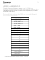
The ELCOM-90 Reference Version consists of the following modules:
1) the ELCOM-90 Service Element (ELCOM-90 provider) which consists of
A) the Application-layer (A-provider)
B) the Presentation-layer (P-provider)
C) the timer system
2) the supervisor
3) the log/trace sub system
4) the application library (A-lib)
5) the adaptation sub system.
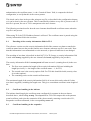
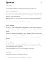
Figure 1 shows the main modules of an ELCOM-90 system.
ELCOM-90
User Element
Application Programming Interface (A-lib)
Supervisor
e90
ad_tls
TLS
ad_x25
ELCOM-90
Service Element
TCP/IP
x.25
Figure 1. The main modules of an ELCOM-90 system.
ELCOM-90 Application Service Element User’s Manual, TR A4124.03
February 2011
11
1) The ELCOM-90 provider is the heart of the system. It is logically divided into three separate
modules:
* the A-provider
* the P-provider
* the timer system.
The ELCOM-90 provider is one software process called e90.
The A-Provider handles the application protocol.
The P-provider is responsible for the handling of the presentation protocol.
Timer supervision of messages is done by both protocols. The timer system supports both
protocols with the basic timer mechanisms.
2) The Supervisor is used to control the ELCOM-90 provider, e.g. start or stop it, turn the log on
or off. The user interface is menu-oriented, though not X-windows or Windows based. The
supervisor is a separate program called superv. Its user interface is described in chapter 7 of
this document.
3) The log/trace system is a common set of routines used by the A- and P-providers. It is
controlled from the supervisor.
The log system will register occurred events and the corresponding actions on a file. An
occurred event is the reception of a message or the expiration of a timer. The corresponding
action is usually that one or more messages are sent to higher or lower layers. The log can be
turned on and off. The A- and P-providers are controlled independently. The log file must be
decoded. This can be done with the supervisor. It is possible to select parts of the logged
information, e.g. with regard to PDU type, connection identification, errors etc.
The Trace system is a similar system. With the trace system turned on it is possible to follow
the control flow through the providers. When special parts of the code is executed, this is
registered in the trace. Routine entry and exit are registered, as well. The trace level can be
chosen between 1 and 5. Level 1 will just give additional information for error conditions
while level 5 will give subroutine name and parameters at routine entry and exit. A and P can
be controlled independently. The trace is written on a file which can be read by a standard text
editor. No decoding is necessary. This information is intended for debugging of the ELCOM90 provider.
4) The Application Programming Interface library (A-lib) provides the interface between the
user program and the ELCOM-90 provider. A-lib conforms to the ELCOM-90 Application
Programming Interface Specification. There are two sets of subroutine names; represented
respectively by small or capital letters. This makes it possible to use the A-lib from both a
FORTRAN and a C written application. The Fortran subroutine set is represented in capital
ELCOM-90 Application Service Element User’s Manual, TR A4124.03
February 2011
12
letters and will be converted from Fortran to C. A-lib will use TLI or sockets as IPC (Inter
Process Communication) mechanism between itself and the ELCOM-90 provider depending
on platform type. Several applications can use the ELCOM-90 provider simultaneously. It is
possible to let the ELCOM-90 provider run on one computer and the applications run on
another computer.
5) The ELCOM-90 provider is able to use X.25 (only Unix versions) or TCP/IP, including
TCP/IP wrapped in TLS as underlying protocols. They will be called ELCOM-90 transport
protocols. To support these various protocols, an adaptation process is developed. This is used
to support the X.25 protocol. The TCP/IP interface (without TLS) is handled directly by the Pprovider. Therefore, in such case an adaptation process is not needed.
The adaptation process and the ELCOM-90 provider may reside on different machines.
Necessary information about this is found in the configuration file (see chapter 6 of this
document).
ELCOM-90 Application Service Element User’s Manual, TR A4124.03
February 2011
13
4
INSTALLATION GUIDE UNIX AND LINUX
The ELCOM-90 software is delivered as a tar-file (typically compressed). This will unpack into a
directory elcom, with four subdirectories:
•
the bin subdirectory contains all binaries, configuration and text files;
•
the include subdirectory contains the public include file, e90pub.h, for the elcom
application interface (alib);
•
the lib subdirectory contains the link library, libelc_alib.a, for the elcom application
interface (alib), and may contain shared libraries used at runtime (depending on the
platform);
•
the test subdirectory contains the elcom FAT test programs
The following files are typically included in the bin directory, may vary slightly depending on
platform:
e90:
The ELCOM-90 provider.
ad_x25:
Adaptation process for X.25.
ad_tls:
Adaptation process for TLS
elc-conf:
Configuration file for the ELCOM-90 installation.
elc-rout:
Legacy routing configuration file, mostly used for X.25.
starte90prov:
Startscript for ELCOM-90 provider (e90). The script contains definition of error
file and should be adjusted according to your installation directory system. Used
when starting e90 from the supervisor (superv).
starte90adap:
Startscript for adaptation process. Used by the provider to start adaptation
processes if used (ad_x25 and/or ad_tls). Should be adjusted as required.
*.txt:
The mandatory text files
- elcom.text: Text strings used by elcom-90 supervisor
- general.text: Text strings used by the trace and log facilities
- error.text:
Error text strings.
prov-alive:
Empty file used as lock file for the provider. The file must be created before
starting the provider.
ELCOM-90 Application Service Element User’s Manual, TR A4124.03
February 2011
14
ad_tls.log_config:
Configuration file for the ad_tls logging (using log4cxx).
elc-xcp:
Sample xcp configuration file.
For a description of configuration files, see chapter 6.
Notes:
If the user element programs are not situated with configuration file (elc-conf), an
environment variable ELCOMPATH may be used to point at the directory containing this
file.
The ad_tls program may use one or more shared libraries supplied in the lib subdirectory.
This may require setting an environment variable for the loader (typically
LD_LIBRARY_PATH), so that these libraries can be found. The starte90adap file should
contain a suitable example of this.
5
INSTALLATION GUIDE WINDOWS
5.1
System Requirements
The Windows version of Elcom-90 is supported on all current, supported versions of
Windows, currently including:
• Windows XP
• Windows V ista
• Windows 7
• Windows Server 2003 and 2003 R2
• Windows Server 2008 and 2008 R2
In general, the most recent service pack is recommended. Older versions of Windows,
including Windows NT and Windows 2000 are not supported.
Elcom-90 for Windows is currently only supported as a 32-bit application, but will run on
64-bit Windows versions. Note that user elements using the supplied alib library will also
need to be 32-bit applications.
Hardware requirements will depend on the size of the Elcom configuration, but in most
cases a pc meeting the minimum requirement for the selected OS will run Elcom-90.
5.2
Installation Procedure
The Elcom-90 Software uses Windows Installer version 3., which is available from Microsoft
if missing from the system. Start the installation by running the ElcomSetup.msi windows
installer file.
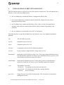
Once the installation is started, you should get this window:
ELCOM-90 Application Service Element User’s Manual, TR A4124.03
February 2011
15
Figure 1 Elcom-90 Setup: Start Screen
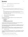
You will then need to accept a license agreement prior to continuing:
Figure 2 License Agreement Dialog
ELCOM-90 Application Service Element User’s Manual, TR A4124.03
February 2011
16
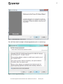
Select the installation type to continue.
Figure 3 Installation Type Dialog
Select Custom to allow detailed selection of components, Typical for a standard runtime
installation or Complete to install everything (Components selected for a Typical installation
is shown below).
ELCOM-90 Application Service Element User’s Manual, TR A4124.03
February 2011
17
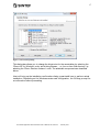
Figure 4 Custom Setup Dialog
This dialog also allows you to change the directories for the executables, by selecting the
' Elcom-90 for Windows' node, and clicking Browse..., or the run-time files directory, by
selecting the ' Elcom Runtime Instance' node. The selectable components are described
below.
Next will bring up the installation confirmation dialog, press Install here to perform actual
installation. Depending on the Windows version and configuration, the OS may prompt for
a confirmation before proceeding.
ELCOM-90 Application Service Element User’s Manual, TR A4124.03
February 2011
18
Figure 5 Installation Confirmation Dialog
A fter completing the setup, reboot the system if requested to.
5.3
Selectable Components
The following is a brief description of the components that can be selected using the Custom setup
type:
•
•
•
•
•
•
5.4
Elcom Provider and Library -- This is the core runtime files for Elcom-90, including the
protocol provider and the dll for the Elcom Alib library.
Elcom TLS Support -- This is adaptation program for communicating using TLS
(encrypted Elcom).
Elcom-90 Runtime Service -- This is the Windows service wrapper for Elcom, which
allows all the Elcom process to be run as a single Windows service).
Software Development Support -- This is the header file and link library for building user
elements for Elcom.
Elcom-90 Test Programs -- These are the test programs used for the tests in the Elcom-90
FAT procedure.
OpenSSL Command Line Utility -- This is the openssl command line utility, which may
be used to generate certificates for Elcom over TLS.
Runtime directory
The Custom setup type allows you to select the Elcom runtime directory, containing log and
configuration files. The default will be to use a separate directory from the executables,
ELCOM-90 Application Service Element User’s Manual, TR A4124.03
February 2011
19
specifically the common application data folder, with the subfolders Elcom\run
(%ALLUSERSPROFILE%\Elcom\run). On Windows XP and 2003 this will typically be:
c:\Documents and Settings\All Users\Application Data\Elcom\Run
whereas on newer windows version, the directory will typically be
c:\ProgramData\Elcom\Run
Note that these directories are often hidden, so that it may be necessary to use ‘Show hidden Files’
in the Windows Explorer.
The installation will copy the files from the templates folder (under the installation folder) to the
run-time folder, but will not overwrite the files if they already exist.
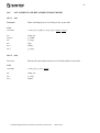
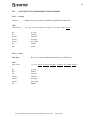
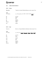
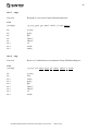
5.5
Files Installed
The following files are installed on the system (for a complete install):
Name
ad_tls.exe
e90.exe
elcman.exe
elcman.ini
superv.exe
curses.dll
Directory
bin
bin
bin
templates
bin
bin
Type
Program
Program
Program
Config
Program
Library
elc_alib.dll
libapr-1.dll
log4cxx.dll
libeay32.dll
ssleay3 2.dll
elc-conf
elc-route
elcom.txt
error.txt
general.txt
ad_tls.log_config
bin
bin
bin
bin
bin
templates
templates
templates
templates
templates
templates
Library
Library
Library
Library
Library
Config
Config
Config
Config
Config
Config
elc-xcp
templates
Config
openssl.cnf
templates
ecap-a.exe
bin
ecap-b.exe
bin
eld-a.exe
bin
eld-b.exe
bin
elt-a.exe
bin
elt-b.exe
bin
openssl.exe
bin
elc_alib.lib
lib
e90pub.h
include
Name Directory Type Usage
Config
Program
Program
Program
Program
Program
Program
Program
Library
Include file
ELCOM-90 Application Service Element User’s Manual, TR A4124.03
Usage
Elcom-90 adaptation for TLS
Elcom-90 protocol provider
Elcom Manager Umbrella service
Configuration for elcman.exe
Elcom-90 supervisor
Emulation of unix curses (for
superv.exe)
Elcom-90 alib
A pache portable run-time
A pache log4cxx library
OpenSSL library
OpenSSL library
Elcom-90 provider configuration
Elcom-90 provider route file
Elcom-90 static text file
Elcom-90 static text file
Elcom-90 static text file
Configuration for log4cxx logging in
ad_tls
eXtended Communication Parameter
file, sample
Configuration file for openssl.exe
Elcom-90 FAT program, capacity test
Elcom-90 FAT program, capacity test
Elcom-90 FAT program, load test
Elcom-90 FAT program, load test
Elcom-90 FAT program, functional test
Elcom-90 FAT program, functional test
OpenSSL utility program
Elcom-90 alib for linking
Elcom-90 definitions
February 2011
20
5.6
Upgrade Procedure
Use the same kit for upgrading the software. The kit will automatically uninstall any prior
version as part of an upgrade. Reboot the computer if prompted to do so. A n upgrade will
normally maintain configuration files from the previous install.
A fter the upgrade, the Elcom Runtime service must be restarted manually.
ELCOM-90 Application Service Element User’s Manual, TR A4124.03
February 2011
21
6
CONFIGURATION
6.1
Overview
Most of the elcom configuration settings is done in a file called elc-conf. the same config file is
used by the elcom provider (e90), the adaptation processes and user elements linked to the elcom
alib. For the provider and adaptation processes, the file must be found in the current working
directory. For user elements, an environment variable, ELCOMPATH, can be used to locate the
file instead. (the variable should then contain the directory name).
Some settings in the config file must always be present in some form, whereas other are only
required with a particular usage (e.g. if a specific transport is used). The programs will generally
complain and exit if a certain setting is missing, in which case it should be added to the file.
The following settings are always required:
• ELC_ERRFILE
• TCP_DEV_1
• SUPERV_SELECTOR
• USER_SELECTOR
• PROV_HOST_ADDR
• ADAPT
• NO_OF_TCP_DEV
• NO_OF_X25_DEV
• NO_OF_ISOT_DEV
• ALOG_FILE
• PLOG_FILE
• LOCK_FILE (not on windows)
6.2
Configuring for TCP/IP communications
To use TCP/IP communications, the NO_OF_TCP_DEV variable should be set to 1, and a valid
TCP_SELECTOR must be supplied, being the TCP/IP port number used by remote partners to
connect to this elcom system.
6.3
Configuring for TLS communications
To use TLS communications, the following settings must be supplied.
• ADAPT set such that bit 3 (0x8) is set.
• ADAP_SRTSCRIPT
• TLS_PROV_SELECTOR set to the public port for TLS communications.
• TLS_AP_SELECTOR
• TLS_AP_HOST_ADDR
• TLS_SELECTOR
ELCOM-90 Application Service Element User’s Manual, TR A4124.03
February 2011
22
•
•
•
TLS_CA_CERT
TLS_MY_CERT
TLS_PRIVATE_KEY
To use TLS, you will as a minimum require a private key and the corresponding X.509 certificate,
as well as the certificate for the certificate authority (CA) that issued the certificate. This identifies
the current node for other systems, which must then have the same CA certificate, in order to
validate the individual partner certificates.
The private key and own certificate may be kept in a single file, and the TLS_PRIVATE_KEY
setting omitted.
The key and certificate files should be in PEM format.
Depending on how the user element is programmed, the installation may also use an xcp file to
define the mapping between partner addresses and certificate names. This file allows the use of
TLS without modifying the user element code, but adds configuration complexity, and may not be
desirable when there are many partners. Without an xcp file, the user element handles
configuration of certificate names, as described later. The use of an xcp file is specified with the
setting XCP_FILE in elc-conf, pointing to the actual file. The format of the xcp file is described
later in this chapter.
6.4
Configuration variables defined by the file elc-conf
The file contains some TCP portnumbers. Find free portnumbers in /etc/services. Usually
portnumbers are from 5995-5999. Edit /etc/services according to your choice (this is not required
for elcom operation).
ADAPT
Meaning:
Read by:
Default value:
Configuration guideline:
Specification of protocol adaptation in use
A- and P-provider
0 (no adaptation)
The variable is a bit mask that describes for which protocols adaptation
is used. Each protocol type is reserved a bit:
TCP : value 0 (no adaptation for TCP protocol)
X.25 : value 2
ISOT : value 4
TLS : value 8
The "ADAPT" variable will be the sum of the values for the protocols
with adaptation. E.g. adaptation for X.25 and ISOT will be specified:
ADAPT=6.
ADAP_SRTSCRIPT
ELCOM-90 Application Service Element User’s Manual, TR A4124.03
February 2011
23
Meaning:
Read by:
Default value:
Configuration guideline:
File containing a script to start the adaptation processes.
A- and P-provider
starte90adapt
A script file will be delivered with the ELCOM software. The file must
be modified according to your system.
ALOG_FILE
Meaning:
Name of and path for file to be used for coded log information from the
A-provider.
Read by:
A- and P-provider
Default value:
ap-log.dat
Configuration guideline: The file is created by the provider. Name and path to the file must be
filled in according to your system.
ELC_ERRFILE
Meaning:
Name of and path to the text file defining error messages for the
ELCOM system.
Read by:
A- and P-provider, A-lib, Supervisor, Accept test programs
Default value:
../bin/error.txt
Configuration guideline: The file is located in the "bin" subdirectory of ELCOM and is named
error.txt. Path to the file must be filled in according to your system.
ELC_TEXTFILE
Meaning:
Name of and path to the text file containing text strings with various
elcom information.
Read by:
Supervisor, Accept test programs
Default value:
../bin/general.txt
Configuration guideline: The file is located in the "bin" subdirectory of ELCOM and is named
general.txt. Path to the file must be filled in according to your system.
ISOT_AP_HOST_ADDR
TCP_AP_HOST_ADDR
X.25_AP_HOST_ADDR
TLS_AP_HOST_ADDR
Meaning:
IP address for adaptation process host
Read by:
A- and P-provider, adaptation process
Default value:
None
Configuration guideline: IP address for the machine running the given adaptation process must
be filled in (refer host file).
ISOT_AP_IPCDEV
TCP_AP_IPCDEV
ELCOM-90 Application Service Element User’s Manual, TR A4124.03
February 2011
24
X.25_AP_IPCDEV
Meaning:
Read by:
Default value:
Configuration:
Device/controller for IPC with provider process (TCP/IP)
Adaptation processes
None
Choose a TCP/IP device on the adaptation process host. Not used by
adaptation for TLS.
ISOT_AP_SELECTOR
TCP_AP_SELECTOR
X.25_AP_SELECTOR
TLS_AP_SELECTOR
Meaning:
Port numbers for listen SAPs in the adaptation processes for incoming
requests from the provider.
Read by:
A- and P-provider, Adaptation processes
Default value:
5995.
Configuration:
TCP port numbers that must be unique to the system.
ISOT_DEV_x
Meaning:
A set of variables describing names of devices/controllers for ISO
Transport.
Read by:
A- and P-provider, Adaptation process
Default value:
None.
Configuration guideline: For each of the devices specified in "NO_OF_ISOT_DEV" a device
name must be given. E.g. ISOT_DEV_1=/dev/isotp. These variables are
only required if NO_OF_ISOT_DEV > 0.
ISOT_PROV_SELECTOR
TCP_PROV_SELECTOR
X.25_PROV_SELECTOR
TLS_PROV_SELECTOR
Meaning:
Port numbers used for listen SAPs in the provider for incoming requests
from adaptation processes.
Read by:
A- and P- provider, Adaptation process
Default value: 5996.
Configuration guideline: TCP is used as IPC mechanism between the provider and the adaptation
processes. Thus, these selectors are TCP port numbers which must be
unique to the system.
ISO_SELECTOR
Meaning:
T-selector used for listen SAP for incoming requests from remote
ELCOM providers using ISO Transport protocol for lower level
communication.
ELCOM-90 Application Service Element User’s Manual, TR A4124.03
February 2011
25
Read by:
Default value:
Configuration guideline:
system.
LOCK_FILE
Meaning:
Read by:
Default value:
Configuration guideline:
MAX_FD_UACEP
Meaning:
Read by:
Default value:
Configuration guideline:
NO_OF_ISOT_DEV
Meaning:
Read by:
Default value:
Configuration guideline:
NO_OF_TCP_DEV
Meaning:
Read by:
Default value:
Configuration guideline:
A- and P-provider, or ISO Transport adaptation process.
None
This is an ISO Transport selector which must be unique to the
Name of and path to the file used to signal that the provider is running.
A- and P-provider, supervisor, Alib.
prov-alive
The file is empty but must be created before the provider can be started.
The file is called a lock file because the provider sets a lock on the file
when it is running. This lock can be checked by the Supervisor to verify
the status and to get the PID (process identification) of the provider
process. The lock file is not used on windows.
Number of UACEP's per file descriptor (TLI connection or socket)
A-lib
10
If many ELCOM Application associations (UACEP's) are used between
Application user and the provider it is possible to split the information
transfer between different TLI or socket connections. The default value
will cause a new connection to be established for every tenth UACEP.
If the variable is omitted, the value will be set to 10 (a new connection
is established for every 10th UACEP).
Number of ISO transport devices/controllers
A- and P-provider, Adaptation process
0
The provider will open a listen SAP for each device.
"ISOT_SELECTOR" (see above) will be used as Transport selector.
Number of TCP devices/controllers
A- and P-provider, Adaptation process
1
There must be at least one TCP/IP device (TCP is used as protocol for
IPC). The provider will open a listen SAP for each device.
"TCP_SELECTOR" (refer below) will be used as port number for all
devices. Set this to 0 to disable use of TCP transport (e.g. to use only
encrypted (TLS) communications).
ELCOM-90 Application Service Element User’s Manual, TR A4124.03
February 2011
26
NO_OF_X.25_DEV
Meaning:
Read by:
Default value:
Configuration guideline:
Number of X.25 devices/controllers
A- and P-provider, Adaptation process
0
The provider will open a listen SAP for each device.
"X.25_SELECTOR" (see below) will be used as subaddress.
PLOG_FILE
Meaning:
Name of and path to file to be used for coded log information from the
P-provider.
Read by:
A- and P-provider
Default value:
pp-log.dat
Configuration guideline: The file is created by the provider. Name and path to the file must be
filled in according to your system.
PONG_TIMER
Meaning:
Number of seconds between each check of TCP/IP connection to a
partner, using “Pong” [9].
Read by:
P-provider
Default value:
0
Configuration guideline: A value of 0 means that this check is not performed. If this check is
activated, a test of the liveness of the remote part will be performed. If a
connection is broken, all connections to this partner will be aborted.
PROV_HOST_ADDR
Meaning:
Read by:
Default value:
Configuration guideline:
Internet address used to identify host for a provider.
A-lib, Adaptation process
System dependent
TCP is used as IPC between the Application users (A-lib) and the
ELCOM provider. Since the users may run on another machine they
must know the IP address for the provider host machine.
ROUTE_FILE
Meaning:
Name of and path to file that contains routing information for outgoing
calls from the provider.
Read by:
A- and P-provider, Adaptation process
Default value:
elc-route
Configuration guideline: The ELCOM system includes a default route file located in the "bin"
subdirectory, which must be modified to fit your current system. The
configuration variable is used to specify the name and location of this
file. Note that the route file is only used by some adaptations for X.25
in the current version.
ELCOM-90 Application Service Element User’s Manual, TR A4124.03
February 2011
27
SUPERV_SELECTOR
Meaning:
Port number used for listen SAP for incoming requests from the
Supervisor.
Read by:
A- and P-Provider
Default value:
5999
Configuration guideline: This is a TCP port number which must be unique to the system.
SUPERV_SRTSCRIPT
Meaning:
Read by:
Default value:
Configuration guideline:
File containing a script to start the ELCOM provider process.
Supervisor
starte90prov
A script file will be delivered with the ELCOM software. The script
must be modified according to your system.
SUPERV_TEXTFILE
Meaning:
Name of text file containing various texts for the Supervisor i.e. menus
etc.
Read by:
Supervisor
Default value:
../bin/elcom.txt
Configuration guideline: The file is located in the "bin" subdirectory of ELCOM and is named
elcom.txt. The path for the file must be filled in according to your
system.
TCP_DEV_x
Meaning:
Read by:
Default value:
Name of devices/controllers for TCP
AP provider, Adaptation process
System dependent
Configuration guideline: For each of the devices specified in "NO_OF_TCP_DEV" a device
name must be given. E.g. TCP_DEV_1=/dev/tcp. Since TCP is used as
protocol for IPC at least one device must be specified. The same device
can, however, be used for lower level communication with TCP. Note
that the value of this is not used for the current, sockets-based provider,
but must still be present in the configuration file.
TCP_SELECTOR
Meaning:
Port number used for listen SAP for incoming requests from remote
ELCOM providers using TCP for lower level communication.
Read by:
A- P-provider, Adaptation process.
Default value:
5997
Configuration guideline: This is a TCP port number which must be unique in the system.
ELCOM-90 Application Service Element User’s Manual, TR A4124.03
February 2011
28
TLS_CA_CERT
Meaning:
The file name of the file containing the certificate(s) for the valid
certificate authorities when using TLS communication.
Read by:
Adaptation process.
Default value:
ca-cert.pem
Configuration guideline: The file is a text file in PEM format.
TLS_MY_CERT
Meaning:
The file name of the file containing the certificate representing this
system in Elcom/TLS communications. The certificate must be issued
by one of the certificate authorities in TLS_CA_CERT.
Read by:
Adaptation process.
Default value:
partner_2.cert
Configuration guideline: The file is a text file in PEM format.
TLS_PRIVATE_KEY
Meaning:
The file name of the file containing the private key for the certificate in
TLS_MY_CERT.
Read by:
Adaptation process.
Default value:
partner_2.cert
Configuration guideline: The file is a text file in PEM format. On multiuser systems it is
important to set permissions on this file so that other users cannot
access it.
TLS_SELECTOR
Meaning:
Port number used to listen for incoming requests from remote ELCOM
providers using TLS for lower level communication.
Read by:
Adaptation process.
Default value:
5991
Configuration guideline: This is a TCP port number which must be unique in the system.
USER_SELECTOR
Meaning:
Port number used for listen SAP for incoming requests from user
entities.
Read by:
A- and P-provider
Default value:
5998
Configuration guideline: This is a TCP port number which must be unique in the system.
X.25_CUDATA
Meaning:
Read by:
Default value:
Data for the "Call user data" field used by the X.25 protocol
Adaptation process for X.25
ELCOM-83
ELCOM-90 Application Service Element User’s Manual, TR A4124.03
February 2011
29
Configuration guideline:
X.25_DEV_x
Meaning:
Read by:
Default value:
Configuration guideline:
Must be set to ELCOM-83 when using X.25.
A set of variables describing name of devices/controllers for X.25.
A- and P-provider, Adaptation process
System dependent
For each of the devices specified in "NO-OF_X.25_DEV" a device
name must be given. E.g. X.25_DEV_1=/dev/x25/dev1. These
variables are only required id NO_OF_X.25_DEV > 0. For Alpha
OSF1, this value is usually ELCOM (Used as Filter Name).
X.25_SELECTOR
Meaning:
X.25 subaddress used for listen SAP for incoming requests from remote
ELCOM providers using X.25 for lower level communication.
Read by:
A- and P-provider, or adaptation process for X.25
Default value:
None
Configuration guideline: This is an X.25 subaddress which must be unique to the system. Must
be removed/commented out on Alpha/OSF1
XCP_FILE
Meaning:
The XCP file (eXtended Communication Parameters) is currently used
to handle mapping between remote addresses and TLS certificate
names.
Read by:
A- and P-provider.
Default value:
None
Configuration guideline: When using an XCP file, the use of TLS instead of TCP is transparent
to the user elements. To let the user elements handle configuration and
validation of certificate names, omit the XCP file.
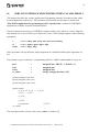
6.5
The elc-xcp configuration file
The elc-xcp (xcp is a mnemonic for eXtended Communication Parameters) configuration file
defines the mapping between partner addresses and certificate names. This allows TLS to be used
without changes to the user element code at the cost of added configuration complexity. The
XCP_FILE setting in elc-conf defines if this file is used or not (as well as the name of the file – it
does not need to be called elc-xcp). Programming for TLS if an xcp file is not used is described in
chapter 9.
A simple xcp file for one partner can look like:
# Lab test configuration for Elcom TLS
192.168.50.2:5991 CONNECT_USING=TLS;PARTNER_CERT=STATNETT_RCCS
ELCOM-90 Application Service Element User’s Manual, TR A4124.03
February 2011
30
Comments start with ‘#’, and there is one line for each address that is mapped. The address is
matched against the addresses in the elcom aconrq call as follows:
•
•
For incoming connections (responder), the initiator address is matched. If a match is
found, the configured certificate name is compared with the name in the partners actual
address, and if not matching, the call is closed, with a result code of 20 returned to the
remote partner.
For outgoing connections (initiator), the acceptor address is matched. If a match is found,
the configured certificate name will be compared to the certificate name of the remote
responder. If not matching, the call will be closed, with a result of 21 returned to the local
user element.
The remaining parameters on the line supply the parameters for the matched address, one or more
separated by semicolons. Currently this is supported for TLS only, and should hence follow the
format in the sample:
•
•
CONNECT_USING should have the vale TLS.
PARTNER_CERT should contain the certificate name for the partner (i.e. the CN field of
the X.509 certificate).
You should supply as many lines in the xcp file as you have addresses for your TLS partners. If a
connect request is received from TLS not matching any line in the xcp file, the call will be
rejected with a result code of 20. For outgoing connections, if an address is not found in the xcp
file, an unencrypted connection will be attempted. If the address points at a TLS port, this will fail
with error code 30.
ELCOM-90 Application Service Element User’s Manual, TR A4124.03
February 2011
31
7
OPERATION AND SUPERVISION
7.1
7.1.1
Windows
Starting and stopping the software
When running Elcom-90 as a service, this service can be started and stopped as any other
windows service, e.g.:
− By using the services control panel applet (under A dministrative Tools in Windows 2000
and newer).
− By using the services MMC snap-in in Windows 2000 and newer (available e.g. in the
Computer
Management Console from A dministrative Tools, or Manage from the context
menu on My Computer).
− By using the NET command from a command line window:
net start ElcomRuntime (to start the service)
net stop ElcomRuntime (to stop the service)
net start (to list active services)
The command is not case sensitive, and the long service name may be used if
quoted.
The Elcom Manager service may also be paused/continued, but this is only intended for testing (a
pause implies suspending the main thread of all child processes).
The elcom provider and adaptation for TLS can also be run as regular command window
programs.
7.1.2
Using Operating System Tools To Monitor the Software
Some useful commands are:
The control panel services applet, to verify that the Elcom Manager service is running.
A lternatively, the ‘net start’ command without a service name lists running services.
The ‘netstat’ command lists active TCP/ IP connections, and is useful to verify if Elcom is
connected. Look for the specified Elcom port (e.g. 5997):
o In the local address column for connections where the local system is responder.
o In The remote address column for connections where the local system is initiator.
The task manager can be used to verify if the processes of a running Elcom system are
active:
o Look for e90.exe (protocol) and elcman.exe (the service/ watchdog program).
7.1.3
Using Other Tools
ELCOM-90 Application Service Element User’s Manual, TR A4124.03
February 2011
32
Some useful third-party tools are available:
From sysinternals (http:/ / www.sysinternals.com):
o Process explorer – a better task manager
o Tcpview – a dynamic TCP/ IP connection viewer
o Dbgview – for dynamic log viewing (if configured in the .log_config files).
A useful, freeware network sniffer, ethereal, is available from http:/ / www.ethereal.com
7.2
Unix
Starting the ELCOM-90 provider process can be done in the following ways:
1. By the start script 'starte90prov'.
2. By using the elcom-90 supervisor.
3. By typing 'e90&' at your keyboard.
The usual way is to use method 1. The script is either started from the system rc file or by the
user. If initiated by the rc file, ELCOM-90 will be running when the system is (re)started.
Method 2 gives the user the possibility to interfere with the provider, change log/trace criteria, do
temporary starts or stops of the ELCOM-90 provider etc. Use of the ELCOM-90 supervisor is
explained in chapter 6.
Method 3 initializes ELCOM-90 from your terminal, and could be used to check the stability of
the software at startup time. Apart from this, method 1 or 2 should be preferred.
8
ADDRESSING
8.1
Addressing
The ELCOM-90 transport protocols are:
1)
2)
3)
4)
TCP/IP
ISO Transport protocol (Not implemented)
X.25 (Not implemented on Windows)
TLS, or TCP/IP wrapped in TLS, for encryption and authentication
According to [1] the address consists of four parts:
1)
2)
Length of lower level part of the address
Lower level part of the address
ELCOM-90 Application Service Element User’s Manual, TR A4124.03
February 2011
33
3)
Length of the A-suffix
4)
A-suffix (or P-selector)
The lower level part of the address is the transport protocol address. It will vary according to the
specific protocol. This is new in ELCOM-90, it is necessary to provide a transport protocol
identifier to the address.
The format of the lower level part of the address will then be:
1)
2)
Protocol identifier field (1 byte)
Transport protocol address.
The protocol identifier field is binary coded, and the values defined are:
1)
2)
3)
4)
5)
128:
129:
130:
131:
132:
X.25
ISO transport protocol
TCP/IP
Reserved for future use (ISO ACSE and Presentation)
Reserved for future use (ISO NSAP)
If the protocol identifier field has a value in the range "0" - "9" (ASCII) this is interpreted as the
old format (ELCOM-83), i.e. an X.25 DTE number.
The ELCOM provider will pass the transport protocol addresses transparently on to the
underlying service. No format conversion will take place. Hence, the application must present the
transport protocol address to the ELCOM provider in the same format as the underlying
communication product expects it.
The adaptation process will in principle receive the same information as the P-provider will send
to the process interface for the protocol in question. This means the protocol identifier is stripped
off when the address is sent to the adaptation process.
For X.25 the address information is sent as BCD digits (i.e. in the way X.25 expects it). The
length of the call address field is in number of bytes. If there are an odd number of BDC digits,
the nibble of the last byte has the value of 0xF (hex), which is the "padding value". See Appendix
A for details about address formats.
9
PROGRAMMING FOR TLS
When using TLS for TCP/IP, Elcom connections are authenticated and encrypted. For the
authentication, X.509 certificates are used. When properly configured, the adaptation for TLS will
validate the certificates according to one or more certificate authorities, but as a final step in the
ELCOM-90 Application Service Element User’s Manual, TR A4124.03
February 2011
34
authentication, the certificate name, i.e. the ‘Canonical Name’ field, is compared with local
configuration, to verify that this is the correct partner.
This check can be done in the provider using an xcp file, as described in the configuration chapter,
or it can be done by the user element. This is controlled by whether an xcp file is present or not. If
this file is present, the use of TLS is transparent to the user element.
The following sections describe how the user elements should handle certificate names when the
xcp file is not present.
When using TLS, the TCP/IP address format is still used. The certificate name is passed using the
security information field in the user data.
9.1
Encoding of the security information field for TLS
The reference version uses the security information field of the connect user data to transfer the
certificate name between the provider and the user elements (when an xcp file is not used). Note
that this information is not transmitted over the network, so protocol behaviour is not changed.
The encoding of user data is described in detail in[7]. For TLS usage, a security information field
is used with aconrq (supplied by the user element) and aconi (supplied by the provider).
The security information field for aconrq/aconi will start at octet 2 (counting from 0) in the user
data.
• The first octet contains the length of the security information field (not including the
length byte itself), i.e. the length of the certificate name + 1, for TLS,
• The second octet is the security options field. For TLS this should be 0x40 (security class
4, no other options).
• The remaining octets are the actual certificate name.
The maximum length of the security information field is 66 octets (this can be reduced if other
user data is supplied), including the length octet. This gives a maximum certificate name length of
64.
9.2
Certificate handling in the initiator
The initiator should supply the certificate name configured for a partner in the user data as
described above, when calling aconrq. The adaptation for TLS will compare this to the partners
actual certificate, and reject the connection if they do not match, returning a result code of 21,
Responder certificate mismatch, in the corresponding aconc call.
9.3
Certificate handling in the responder
ELCOM-90 Application Service Element User’s Manual, TR A4124.03
February 2011
35
The responder needs to compare the certificate name passed up from the provider with the
certificate name configured for the partner in question (based on the initiator address received).
The responder will receive a certificate name with the aconi call. If the certificate name does not
match the configured name, the responder should reject the call with a result code of 20,
certificate reject by responder, in the following aconrs call. For aconrs, no TLS information is
needed.
ELCOM-90 Application Service Element User’s Manual, TR A4124.03
February 2011
36
10
SERVICE INTERFACE PROCEDURES WHEN CALLED FROM C
This chapter describes the various Application Programming Interface Procedures when called
from an application written in C. The parameter specifications are the same as described in
"ELCOM-90 Application Programming Interface Specification" (written for FORTRAN
applications) with the exception mentioned below.
The first element in an array in a FORTRAN program will be given index no 1 (one), while the
first element in a C-array will be given index no 0 (zero). These changes applies to the following
parameters:
t
cf
result
used in: adtrq, adti, actrq, acti, actrs, actc, amdrq,
used in: agmrs, agmc, adgrs, adgc
used in: adgrs, adgc
In the procedure call specification, output arguments are underlined while input arguments are
not.
The parameter types used in the C programming interface which are not standard C types are:
bool
octet
octets
rr_values
=
=
=
=
unsigned char, TRUE = 1, FALSE = 0
unsigned char
unsigned char
integer (ranging from 0 to 255)
typedef unsigned char bool:
typedef unsigned char octet;
typedef unsigned char octets;
typedef enum {
a_r0, a_rcl, a_rc2, ...... a_rc19,
a_r20, ......a_r29,
a_rc30, ,,,
...........
a_r254,
a_runknown
/* 255 */
}rr_values;
The description of the various values of rr_values is found in [1].
ELCOM-90 Application Service Element User’s Manual, TR A4124.03
February 2011
37
Three additional status return values have been implemented for this Elcom implementation:
Status = -6
‘Temporary unavailable (Try again)’.
This may be returned on some platforms if the adaptation process for X.25 is not
running.
Status = -7
‘Operation cancelled due to local error’.
This is returned when the provider can’t complete this call. Eg. if the address does
not match the addresses in the routing table, this error can be given instead of
Illegal parameter.
Status = -8
‘Incompatible version’.
This is used when an ELCOM-90 system communicates with an ELCOM-83
system. If the user is not aware of this and issues an ELCOM-90 primitive, the
provider will return this status.
10.1
INITIATION
10.1.1
ainit
Function:
Initiates the Application Service Provider.
Call:
void ainit
(status)
int * status;
ELCOM-90 Application Service Element User’s Manual, TR A4124.03
February 2011
38
10.2
ATTACHMENT AND DETACHMENT PROCEDURES
10.2.1
aatt
Function:
Make a binding from a User Entity to the A-provider.
Call:
void aatt
( entity_id, a_suffix, u_acep, type, status, p acep )
int
octets *
int
int
int *
entity_id;
a_suffix;
u_acep;
type;
status;
int *
p_acep;
10.2.2
adet
Function:
Release the association between a User Entity and the A-provider.
Call:
void adet
( entity_id, p_acep, status )
int
int
int *
entity_id;
p_acep;
status;
ELCOM-90 Application Service Element User’s Manual, TR A4124.03
February 2011
39
10.3
CONNECTION ESTABLISHMENT PROCEDURES
10.3.1
aconrq
Function:
Request the A-provider to establish an Application Connection.
Call:
void aconrq
( p_acep, version, initiator, acceptor, user_data, length, status )
int
int
octets *
octets *
octets *
int
int *
10.3.2
p_acep;
version;
initiator;
acceptor;
user_data;
length;
status;
aconi
Function:
Receive a Connect Indication initiated by a calling User.
Call:
void aconi
( p_acep, status, version, initiator, acceptor, user_data, length )
int
int *
int *
octets *
octets *
octets *
int *
p_acep;
status;
version;
initiator;
acceptor;
user_data;
length;
ELCOM-90 Application Service Element User’s Manual, TR A4124.03
February 2011
40
10.3.3
aconrs
Function:
Send a response to a received Connect Indication.
Call:
void aconrs
( p_acep, version, initiator, acceptor, result, user_data, length, status)
int
int
octets *
octets *
rr_values
octets *
int
int *
p_acep;
version;
initiator;
acceptor;
result;
user_data;
length;
status;
10.3.4
aconc
Function:
Receive a Connect Confirmation.
Call:
void aconc
( p_acep, status, version, initiator, acceptor, result, user_data, length)
int
int *
int *
octets *
octets *
rr_values *
octets *
int *
p_acep;
status;
version;
initiator;
acceptor;
result;
user_data;
length;
ELCOM-90 Application Service Element User’s Manual, TR A4124.03
February 2011
41
10.4
CONNECTION TERMINATION PROCEDURES
10.4.1
arelrq
Function:
Initiate the termination of a Connection.
Call:
void arelrq
( p_acep, user_reason, status )
int
octet
int *
p_acep;
user_reason;
status;
10.4.2
areli
Function:
Receive a Release Indication initiated by the other User.
Call:
void areli
( p_acep, status, user_reason )
int
int *
octet *
p_acep;
status;
user_reason;
10.4.3
arelrs
Function:
Initiate a response to a received Release Indication.
Call:
void arelrs
( p_acep, result, status )
int
rr_values
int *
p_acep;
result;
status;
ELCOM-90 Application Service Element User’s Manual, TR A4124.03
February 2011
42
10.4.4
arelc
Function:
Receive a Release Confirmation.
Call:
void arelc
( p_acep, status, result )
int
int *
rr-values *
p_acep;
status;
result;
10.4.5
apabt
Function:
Receive a provider initiated Abort Indication.
Call:
void apabt
( p_acep, status, reason )
int
int *
rr_values *
p_acep;
status;
reason;
ELCOM-90 Application Service Element User’s Manual, TR A4124.03
February 2011
43
10.5
GROUP MANAGEMENT
10.5.1
agmrq
Function:
Transfer a Request for Group Management to remote User.
Call:
void agmrq
( p_acep, function, gtype, gnr, gsize, objlength, persist, static,
priority_class, status )
int
int
int
int
int
int
bool
bool
int
int *
p_acep;
function;
gtype;
gnr;
gsize;
objlength;
persist;
static;
priority_class;
status;
10.5.2
agmi
Function:
Receive a Group Management Indication from the remote User.
Call:
void agmi
int
int *
int *
int *
int *
int *
int *
bool *
bool *
int *
( p_acep, status, function, gtype, gnr, gsize, objlength, persist, static,
priority_class )
p_acep;
status;
function;
gtype;
gnr;
gsize;
objlength;
persist;
static;
priority_class;
ELCOM-90 Application Service Element User’s Manual, TR A4124.03
February 2011
44
10.5.3
agmrs
Function:
Return a Response on a received Group Management Indication.
Call:
void agmrs
( p_acep, function, gtype, gnr, cf, result, status )
int
int
int
int
int *
rr_values
int *
p_acep;
function;
gtype;
gnr;
cf;
result;
status;
10.5.4
agmc
Function:
Receive a Confirmation on a transmitted Group Management Request.
Call:
void agmc
( p_acep, status, function, gtype, gnr, cf, result )
int
int *
int *
int *
int *
int *
rr_values *
p_acep;
status;
function;
gtype;
gnr;
cf;
result;
ELCOM-90 Application Service Element User’s Manual, TR A4124.03
February 2011
45
10.6
GROUP DEFINITION
10.6.1
adgrq
Function:
Transfer a Group Definition Request to the remote User.
Call:
void adgrq
( p_acep, gtype, gnr, index1, index2, objid, status )
int
int
int
int
int
octets *
int *
p_acep;
gtype;
gnr;
index1;
index2;
objid;
status;
10.6.2
adgi
Function:
Receive a Group Definition Indication from remote User.
Call:
void adgi
( p_acep, size, status, gtype, gnr, index1, index2, objid )
int
int
int *
int *
int *
int *
int *
octets *
p_acep;
size;
status;
gtype;
gnr;
index1;
index2;
objid;
ELCOM-90 Application Service Element User’s Manual, TR A4124.03
February 2011
46
10.6.3
adgrs
Function:
Respond to a received Group Definition Indication.
Call:
void adgrs
( p_acep, gtype, gnr, index1, index2, cf, result, status )
int
int
int
int
int
int *
int *
int *
p_acep;
gtype;
gnr;
index1;
index2;
cf;
result;
status;
10.6.4
adgc
Function:
Receive a Confirmation on a transmitted Group Definition Request.
Call:
void adgc
( p_acep, size, status, gtype, gnr, index1, index2, cf, result )
int
int
int *
int *
int *
int *
int *
int *
int *
p_acep;
size;
status;
gtype;
gnr;
index1;
index2;
cf;
result;
ELCOM-90 Application Service Element User’s Manual, TR A4124.03
February 2011
47
10.7
READOUT OF GROUP DEFINITION
10.7.1
aggrq
Function:
Request the remote User for a specific Group Definition.
Call:
void aggrq
( p_acep, gtype, gnr, index1, index2, status )
int
int
int
int
int
int *
p_acep;
gtype;
gnr;
index1;
index2;
status;
10.7.2
aggi
Function:
Receive an Indication on a Request for a Group Definition readout.
Call:
void aggi
( p_acep, status, gtype, gnr, index1, index2 )
int
int *
int *
int *
int *
int *
p_acep;
status;
gtype;
gnr;
index1;
index2;
ELCOM-90 Application Service Element User’s Manual, TR A4124.03
February 2011
48
10.7.3
aggrs
Function:
Call:
void aggrs
int
int
int
bool
bool
int
int
int
int
int
octets *
rr_values
int *
10.7.4
Return a readout of requested Group Definition.
( p_acep, gtype, gnr, persist, static, priority_class, gsize, index1, index2,
objlength, objid, result, status )
p_acep;
gtype;
gnr;
persist;
static;
priority_class;
gsize;
index1;
index2;
objlength;
objid
result;
status;
aggc
Function:
Call:
void aggc
int
int
int *
int *
int *
bool *
bool *
int *
int *
int *
int *
int *
octets *
rr_values *
Receive a requested Group Definition readout.
( p_acep, size, status, gtype, gnr, persist, static, priority_class, gsize,
index1, index2, objlength, objid, result )
p_acep;
size;
status;
gtype;
gnr;
persist;
static;
priority_class;
gsize;
index 1;
index2;
objlength;
objid;
result;
ELCOM-90 Application Service Element User’s Manual, TR A4124.03
February 2011
49
10.8
INFORMATION TRANSFER
10.8.1
aitrq
Function:
Request the remote User for information from a Group.
Call:
void aitrq
( p_acep, gtype, gnr, index1, index2, to, dt, t_unit, periods, status )
int
int
int
int
int
int *
int
int
int
int *
p_acep;
gtype;
gnr;
index1;
index2;
to;
dt;
t_unit;
periods;
status;
10.8.2
aiti
Function:
Receive an Init Transfer Indication.
Call:
void aiti
( p_acep, status, gtype, gnr, index1, index2, to, dt, t_unit, periods)
int
int *
int *
int *
int *
int *
int *
int *
int *
int *
p_acep;
status;
gtype;
gnr;
index1;
index2;
to;
dt;
t_unit
periods;
ELCOM-90 Application Service Element User’s Manual, TR A4124.03
February 2011
50
10.8.3
adtrq
Function:
Call:
void adtrq
int
int
int
int
int
int
int *
bool
octets *
int
rr_values
int *
10.8.4
Transfer one group of information from a group to the remote user or
indicate an erroneous initiation of data transfer.
( p_acep, gtype, gnr, transmod, index1, index2, t, more_d, data, length,
result, status )
p_acep;
gtype;
gnr;
transmod;
index1;
index2;
t;
more_d;
data;
length;
result;
status;
adti
Function:
Call:
void adti
int
int
int *
int *
int *
int *
int *
int *
int *
bool *
octets *
int *
rr_values *
Receive information from a (sub)group or an error indication from the
remote User.
( p_acep, size, status, gtype, gnr, transmod, index1, index2, t, more_d,
data, length, result )
p_acep;
size;
status;
gtype;
gnr;
transmod;
index1;
index 2;
t;
more_d;
data;
length;
result;
ELCOM-90 Application Service Element User’s Manual, TR A4124.03
February 2011
51
10.8.5
acdrq
Function:
Confirm the reception of the last ADTI in a sequence of ADTIs received
from the remote User, or report an error situation.
Call:
void acdrq
( p_acep, gtype, gnr, transmod, result, status )
int
int
int
int
rr_values
int *
p_acep;
gtype;
gnr;
transmod;
result;
status;
10.8.6
acdi
Function:
Receive a Confirm Data Indication.
Call:
void acdi
( p_acep, status, gtype, gnr, transmod, result )
int
int *
int *
int *
int *
rr_values *
p_acep;
status;
gtype;
gnr;
transmod;
result;
10.8.7
asmrq
Function:
Request the remote User to start or stop spontaneous information
transfer.
Call:
void asmrq
( p_acep, function, gtype, gnr, status )
int
int
int
int
int *
p_acep;
function;
gtype;
gnr;
status;
ELCOM-90 Application Service Element User’s Manual, TR A4124.03
February 2011
52
10.8.8
asmi
Function:
Receive a Spontaneous Management Indication.
Call:
void asmi
( p_acep, status, function, gtype, gnr )
int
int *
int *
int *
int *
p_acep;
status;
function;
gtype;
gnr;
10.8.9
asmrs
Function:
Respond to a received Spontaneous Management Indication.
Call:
void asmrs
( p_acep, function, gtype, gnr, result, status )
int
int
int
int
rr_values
int *
p_acep;
function;
gtype;
gnr;
result;
status;
10.8.10 asmc
Function:
Receive a Spontaneous Management Confirmation.
Call:
void asmc
( p_acep, status, function, gtype, gnr, result )
int
int *
int *
int *
int *
rr_values *
p_acep;
status;
function;
gtype;
gnr;
result;
ELCOM-90 Application Service Element User’s Manual, TR A4124.03
February 2011
53
10.8.11 actrq
Function:
Call:
void actrq
int
int
int
int
int
int *
int
int
octets *
int
int *
Transfer one Command or Setpoint Data Block to the Remote Side.
( p_acep, gtype, gnr, index1, index2, t, time_mode, com_type, data,
length, status )
p_acep;
gtype;
gnr;
index1;
index2;
t;
time_mode;
com_type;
data;
length;
status;
10.8.12 acti
Function:
Call:
void acti
int
int
int *
int *
int *
int *
int *
int *
int *
int *
octets *
int *
Receive one Command or Setpoint Data Block from the Remote Side.
( p_acep, size, status, gtype, gnr, index1, index2, t, time_mode,
com_type, data, length )
p_acep;
size;
status;
gtype;
gnr;
index1;
index2;
t;
time_mode;
com_type;
data;
length;
ELCOM-90 Application Service Element User’s Manual, TR A4124.03
February 2011
54
10.8.13 actrs
Function:
Call:
void actrs
int
int
int
int
int
int *
int
int
octets *
int
rr_values
int *
Respond to one Command or Setpoint Data Block.
( p_acep, gtype, gnr, index1, index2, t, time_mode, com_type, data,
length, result, status )
p_acep;
gtype;
gnr;
index1;
index2;
t;
time_mode;
com_type;
data;
length;
result;
status;
10.8.14 actc
Function:
Call:
void actc
int
int
int *
int *
int *
int *
int *
int *
int *
int *
octets *
int *
rr_values *
Receive an A-Command-Transfer Confirmation Data Block from the
RTU side.
( p_acep, size, status, gtype, gnr, index1, index2, t, time_mode,
com_type, data, length, result )
p_acep;
size;
status;
gtype;
gnr;
index1;
index2;
t;
time_mode;
com_type;
data;
length;
result;
ELCOM-90 Application Service Element User’s Manual, TR A4124.03
February 2011
55
10.8.15 amdrq
Function:
Send Spontaneous Mixed Data.
Call:
void amdrq
( p_acep, t, data, length, status )
int
int *
octets *
int
int *
p_acep;
t;
data;
length;
status;
10.8.16 amdi
Function:
Receive Mixed Data Indication.
Call:
void amdi
( p_acep, size, status, t, data, length )
int
int
int *
int *
octets *
int *
p_acep;
size;
status;
t;
data;
length;
10.8.17 amderq
Function:
Report that an error is detected in the Data Field of a received AMDI.
Call:
void amderq ( p_acep, gnr, result, status )
int
int
rr_values
int *
p_acep;
gnr;
result;
status;
ELCOM-90 Application Service Element User’s Manual, TR A4124.03
February 2011
56
10.8.18 amdei
Function:
Report that an error is detected in the Data Field of a received AMDI.
Call:
void amderq ( p_acep, gnr, result, status )
int
int
rr_values
int *
p_acep;
gnr;
result;
status;
10.9
TEST CONNECTION
10.9.1
atcrq
Function:
Test that the remote User can be reached and is alive.
Call:
void atcrq
( p_acep, status )
int
int *
p_acep;
status;
10.9.2
atci
Function:
Receive an A-Test-Connection Indication.
Call:
void atci
( p_acep, status )
int
int *
p_acep;
status;
ELCOM-90 Application Service Element User’s Manual, TR A4124.03
February 2011
57
10.9.3
atcrs
Function:
Respond to a received A-Test-Connection Indication.
Call:
void atcrs
( p_acep, result, status )
int
rr_values
int *
p_acep;
result;
status;
10.9.4
atcc
Function:
Receive an A-Test-Connection Confirmation.
Call:
void atcc
( p_acep, status, result )
int
int *
rr_values *
p_acep;
status;
result;
10.10
EVENT WAITING PROCEDURES
10.10.1 aswait
Function:
Wait for some event significant to the User on a given ACEP.
Call:
void aswait
( p_acep, timeout, status, event )
int
int
int *
int *
p_acep;
timeout;
status;
event;
ELCOM-90 Application Service Element User’s Manual, TR A4124.03
February 2011
58
10.10.2 agwait
Function:
Wait for some event significant to the User on any ACEP.
Call:
void agwait
( entity_id, timeout, status, u_acep, event )
int
int
int *
int *
int *
entity_id;
timeout;
status;
u_acep;
event;
ELCOM-90 Application Service Element User’s Manual, TR A4124.03
February 2011
59
11
SUPERVISOR GUIDE
The ELCOM-90 Supervisor is a user tool to control and supervise the ELCOM-90 provider
process.
The Supervisor program is menu-based and provides the user with context-sensitive help on the
various functions.
The ELCOM-90 supervisor includes the following functions:
-
Start/Stop/Restart of the A- and P-providers. (Only Unix)
Control of the Log system
Control of the Trace system
Display of Status and Configuration information.
Forced Disconnect of individual connections.
The start function uses shell script to start the provider process.
The control of the log system involves not only turning the log function on or off, but enables the
user to select decode levels for interpretation of the logged information.
The trace function enables the user to turn the trace on or off and to select wanted trace level.
The configuration and status functions display information regarding configuration (compile date,
maximum number of UACEPs etc.) and status information (the number of active UACEPs, and
what state they are in etc.).
The user can terminate one specific connection with the forced disconnect menu option.
ELCOM-90 Application Service Element User’s Manual, TR A4124.03
February 2011
60
11.1
USER INTERFACE
When the Supervisor is invoked it will run as a Menu Oriented Full Screen application.
The supervisor is started in a command shell (Unix) or cmd window( Windows) by moving to the
supervisor's "home" directory and executing the command:
superv
The menu system only supports one type of menu orientation, that is horizontal menus: On top of
the screen one line contains a list of commands available. A command is executed by moving the
cursor to that command and press ENTER or DOWN, or by typing the first characters of the
command. The command may lead to another line of commands on the next line (several levels of
commands), or that the command is executed. The command name that is executed is highlighted.
11.2
MMI FUNCTIONS
11.2.1
Functions
The ELCOM-90 Supervisor will supply the user with the following functions:
-
Start the providers (Only Unix)
Stop the providers (Only Unix)
Reset the providers
Forced Disconnect of individual connections
Display of Status and Configuration information
Start the Log
Stop the Log
Close the Log
Decode the Log
Change the Trace Level
Start the Trace
Stop the Trace.
These functions will now be described in more detail, as they appear in the command tree.
ELCOM-90 Application Service Element User’s Manual, TR A4124.03
February 2011
61
11.2.2
Start of the providers (Only Unix)
Start providers assures a correct sequenced start of the A- and P-providers.
The Supervisor tries to start the A/P-provider by "Kicking off" a script which again starts the
provider process. The Supervisor then sends a "RESET-ENTITY" message on the IPC-port to the
provider. It waits a certain time for an acknowledge from the provider. If no acknowledge is
received, an error message is displayed.
If the provider is already running, this will be indicated.
If the provider is not started correctly, and the reason is not indicated when the script is run, the
process will write error information to a standard error file. The Supervisor may then
automatically display the last few lines of that error file indicating the type of error which has
occurred. This could in some cases lead to some confusion on your screen or window.
11.2.3
Stop the providers (Only Unix)
Stop Providers will stop the provider process. The command is located on level 2 in the command
tree under the PROVIDER-CONTROL level 1 command.
Before the process is stopped, the providers will take the following actions to stop ongoing
activity:
-
Deactivate all active timers
Detach PCEP's ("forced")
Send A-P-ABORT to all ACEP's
Close LOG-files
Close TRACE-files.
The Supervisor first checks if the provider is up and running. If this condition is true, it sends a
special stop request to the provider. If the provider is not able to respond to the stop request for
one reason or another, the Supervisor stops the provider process abruptly.
ELCOM-90 Application Service Element User’s Manual, TR A4124.03
February 2011
62
11.2.4
Reset the providers
Reset providers sets the providers back to initial state. The command is located under the
PROVIDER-CONTROL level 1 command in the command tree.
The Supervisor sends a "RESET-ENTITY" command to the provider, which takes the following
actions:
-
Disconnect network connections.
Deactivate all active timers
Stop data transfer
Initialize data
Close LOG-files
Close TRACE-files.
Reset is only allowed if the provider process is active.
11.2.5
Forced Disconnect
On invoking the FORCED-DISCONNECT command the user is prompted to input the UACEP
number to be disconnected. The command is located under the PROVIDER-CONTROL level 1
command.
The Supervisor sends a "FORCED-DISCONNECT" command to the provider, which in turn
terminates the specified connection. If no connection exist with the UACEP number specified by
the user or an error occurs during the execution of the command, a message will be displayed to
notify the user.
The information needed to "kill" a specific connection will be available to the user through the
"Status" command (ref. 7.2.6.).
ELCOM-90 Application Service Element User’s Manual, TR A4124.03
February 2011
63
11.2.6
Status information
The Status function will display information regarding to either the A- or the P-provider. The
command is divided on level 2 in an A-PROVIDER and an P-PROVIDER option. On level 3 the
user can select ASAP or PACEP under the A-PROVIDER level 2 command and PSAP or PPCEP
under the P-PROVIDER level 2 command.
The ASAP command will display the following information:
-
User Entity identifier
Number of PACEP's
The PACEP command will display the following information:
-
PACEP identifier
State
Substate
The PSAP command displays:
-
PSAP identifier
Service User Entity - identifier (A-Provider)
Number of PPCEP's
The PPCEP command displays:
-
PPCEP identifier
State
Connection type
PPCEP blocked up to A. That is, if the A-Provider of flow-control reasons have
blocked the P-provider from sending more information up.
PPCEP blocked down to transport/network. That is, if the P-provider has attempted
to send data to the lower layer, and the lower layer has refused to accept the data, the
P-Provider will block the A-Provider from sending more data down to the PProvider.
The information described above will be presented to the user in the INPUT/OUTPUT field.
ELCOM-90 Application Service Element User’s Manual, TR A4124.03
February 2011
64
11.2.7
Configuration information
Invocation of the Configuration function will present to the user the A- and P-providers
configuration data. The commands are invoked by choosing either the A-PROVIDER or PPROVIDER command from the menu under the CONFIG level 1 command.
A-PROVIDER will display various Application entity information, and P-PROVIDER will
display the state time limits and connections related to the Presentation Entity.
The configuration information for the A- and P-providers will be presented to the user in the
INPUT/OUTPUT field.
11.2.8
Log
By activating the log function the user can initiate, stop and decode the logging of events.
-
Start log initiates logging of the desired provider (A or P). Current log state is reported in a
supervisory field. A- and P-provider use separate log files.
-
Stop log disables (ongoing) logging of the A- and P-provider respectively. The corresponding
log file is not closed, which makes it possible to restart logging without destroying the file
content, ie. execute start log.
-
Close log disable logging and closes the corresponding log file. The log file content can be
converted by DECODE log.
-
DECODE log formats the log file content into readable form. On the two first lines in the
INPUT/OUTPUT field the user is asked to input the names of the files were the information
to be decoded is located and where the decoded information is to be stored. In the lower part
of the input/output area the user selects what information he wants extracted from the log file.
To know what to select from the log file, it might be useful to study more closely the possibilities
that exists.
A typical log block is built up in the following manner:
Event occurred
Time
State-change
Message dump
:
:
:
:
P-Attach
Ppcep:0
8.15.47 ( e.t. 7999 )
Date: 24.10.91
sta1 : Idle ==> sta2 : Ready for connect
0 56 0 1 98 98 0 2 0 2 0 14
The information under the message dump heading always relates to the event on the first line.
ELCOM-90 Application Service Element User’s Manual, TR A4124.03
February 2011
65
The content of the log block tells the user what event happened, on what PPCEP the event
happened at what time/date it happened, what state change the event led to and what information
the package contained. The numbers presented in the parentheses immediately following the time,
represent an internal millisecond counter. This is added to help the user distinguish between log
blocks received on the same second. In the example below the log block also contains the events
that was generated in the "upwards" and the "downwards" direction, as a result of the incoming
event. The field "TLI-error" will contain the currently active text reference to the value in the
system variable t_error.
Event occurred
Time
State.change
Ppenerated
TLI-error
Message dump
:
:
:
:
:
:
P-Connect request
PPCEP: 1
8.15.51 ( e.t. 8445 )
Date: 24.10.91
sta2: Ready for connect ==> sta3: Establishing lower level
P-Connect request answer
Ngenerated: Network Connect VC request
No message currently available
0 58 0 1 17 130 0 2 23 109 130 67
46 51 0 0 0 0 0 0 0 0 0 ..........
The user can select to decode one, several or all the different events that have occurred in the two
providers in the input field under the decode command. To decode all of the events the user
answers yes(Y) on the line "All Information: N", to decode only the log blocks that contain an
error, the user answers yes (Y) on the line "All log blocks with error code unequal zero: N". On
the next lines the user can select one or several of the PPCEP, P-PDU and P-SDU identifiers,
alone or separated by a comma. If the user wants to decode all log blocks related to PPCEP's 1,2,3
and 4, he would have to write after the heading "All log blocks for this set of PPCEP's": "
1,2,3,4" or "1:4". In general, commas are used to separate single numbers and colon is used to
indicate a range of values.
The following P-PDU ID values can be selected from the Supervisor/P-provider log decode
function:
0
1
2
3
8
:
:
:
:
:
Connect Request/ Connect Indication
Connect Response/ Connect Confirmation
Release Request/ Release Indication
Release Response/ Release Confirmation
Data Request/ Data Indication
The following P-SDU ID values can be selected from the Supervisor/ P-provider log decode
function:
56 :
57 :
58 :
59 :
60 :
61 :
Presentation Attach
Presentation Detach
Presentation Connect request
Presentation Connect indication
Presentation Connect response
Presentation Connect confirm
ELCOM-90 Application Service Element User’s Manual, TR A4124.03
February 2011
66
62 :
63 :
64 :
65 :
66 :
67 :
68 :
69 :
Presentation Release request
Presentation Release indication
Presentation Release response
Presentation Release confirm
Presentation Provider Abort
Presentation Data request
Presentation Data indication
Presentation Data acknowledge
The following N.SDU ID values can be selected from the Supervisor/ P-provider log decode
function:
8 :
9 :
10 :
11 :
12 :
13 :
14 :
15 :
16 :
17 :
18 :
19 :
20 :
21 :
22 :
23 :
24 :
Network Connect VC request
Network Connect VC indication
Network Connect VC response
Network Connect VC confirm
Network Disconnect VC request
Network Disconnect VC request failure
Network Disconnect VC indication
Network Data request
Network Data request failure
Network Data indication
Network Data Accept request
Network Data Accept request failure
Network Data Accept indication
Network Reset request
Network Reset indication
Network Reset response
Network Reset confirm
By choosing the A.PROVIDER option under the "LOG" heading, the user is presented a similar
screen to that of the P-PROVIDER option.
PROVIDERCONTROL
A-PROVIDER
!START
STATUS
CONFIG
P-PROVIDER
!STOP
!CLOSE
LOG
TRACE
DECODE
Input file name to decode: /usr/elcom90/testvers/bin/ap-log.dat
Input file name to write decoded information: ap-log.txt
Selection Criteria:
All Information: N
All log blocks with error unequal zero: N
ELCOM-90 Application Service Element User’s Manual, TR A4124.03
February 2011
QUIT
[Level 1]
[Level 2]
[Level 3]
67
All log blocks for this set of PACEP's:
All log blocks for this set of A-PDU's:
All log blocks for this set of A-SDU's:
All log blocks for this set of P-SDU's:
_______General Status Information_________________________________________________
Log - A: OFF
Trace: ON
|
Provider: RUNNING
Log - P: OFF
Trace Level: 3
|
Connection to Providers: UP
The following A-PDU ID values can be selected from the Supervisor/ A-provider log decode
function:
1
2
4
5
8
9
10
11
16
17
24
32
33
34
35
46
47
64
65
255
:
:
:
:
:
:
:
:
:
:
:
:
:
:
:
:
:
:
:
:
Group Management Request
Group Management Response
Connect Request
Connect Response
Define Group Request
Define Group Response
Get Group Request
Get Group Response
Spont-Mgnt Request
Spont-Mgnt Response
Init Transfer
Send Data
Confirm Data
Send Mixed-Data Request
Send Mixed-Data Error Request
Command Transfer Request
Command Transfer Response
Test Connection Request
Test Connection Response
Error PDU
The following A-SDU ID values can be selected from the Supervisor/A-provider log decode
function:
3
4
5
6
7
8
9
10
11
12
13
14
15
:
:
:
:
:
:
:
:
:
:
:
:
:
Application Attach
Application Detach
Application Connect request
Application Connect indication
Application Connect response
Application Connect confirm
Application Release request
Application Release indication
Application Release response
Application Release confirm
Application Release abort
Application Group-Mgnt request
Application Group-Mgnt indication
ELCOM-90 Application Service Element User’s Manual, TR A4124.03
February 2011
68
16
17
18
19
20
21
22
23
24
25
26
27
28
29
30
31
32
33
34
35
36
37
38
39
40
41
42
43
44
45
46
47
48
49
50
:
:
:
:
:
:
:
:
:
:
:
:
:
:
:
:
:
:
:
:
:
:
:
:
:
:
:
:
:
:
:
:
:
:
:
Application Group-Mgnt response
Application Group-Mgnt confirm
Application Def-Group request
Application Def-Group indication
Application Def-Group response
Application Def-Group confirm
Application Get-Group request
Application Get-Group indication
Application Get-Group response
Application Get-Group confirm
Application Init-Transfer request
Application Init-Transfer indication
Application Data-Transfer request
Application Data-Transfer indication
Application Confirm-Data request
Application Confirm-Data indication
Application Spontan-Mgnt request
Application Spontan-Mgnt indication
Application Spontan-Mgnt response
Application Spontan-Mgnt confirm
Application Test-Connection request
Application Test-Connection indication
Application Test-Connection response
Application Test-Connection confirm
Application Command-Transfer request
Application Command-Transfer indication
Application Command-Transfer response
Application Command-Transfer confirm
Application Mixed-Data request
Application Mixed-Data indication
Application Mixed-Data-Error request
Application Mixed-Data-Error indication
Application Timeout
Application user ack
Application provider ack
In addition the P-SDU's that are mentioned earlier can be selected. The Decode Log commands
can only be invoked after the corresponding Log file is closed.
ELCOM-90 Application Service Element User’s Manual, TR A4124.03
February 2011
69
11.2.9
Trace
The Trace function enables the user to turn trace on and off and to set trace levels.
11.2.9.1 Change Trace Level
The commands are used to change the current trace level for the providers. The commands will
cause a signal to be sent to the providers. A designated signal handling routine change the internal
value of the Trace level in the provider.
Default Trace level is 1. (Trace level 1 is the "lowest" trace level, giving the smallest amount of
data output).
Trace levels can be turned up and down during Trace sessions.
11.2.9.2 Start Trace
The "TRACE ; START" command enable the Trace function for the providers. The provider will
make a Trace output corresponding to the current Trace level (which can be the default value or a
modified value). The output is made to the file "tracefile" located on the providers "home"
directory.
The providers will output information in ASCII format, which allows the user to inspect the trace
information directly, for example with the UNIX function "tail -f".
If a Start Trace command is given to a provider for which trace is already active, this will be
indicated.
11.2.9.3 Stop Trace
The "TRACE ; STOP" command is used to disable Trace session. The command will turn the
Trace off by sending a command to the provider, and close the corresponding Trace file. A Stop
Trace command will not affect the Trace level.
A Stop Trace command is only valid if Trace is active for the given provider.
11.2.10 Quit
This functions exits the user to the operating system shell.
ELCOM-90 Application Service Element User’s Manual, TR A4124.03
February 2011
70
12
APPLICATION AND PRESENTATION PROVIDER
The application and presentation providers are implemented as one single process, which handles
the specified function of the A- and P-protocol. The process is called 'e90'.
As stated in chapter 1, there are tools available to control the providers' behaviour during runtime;
-
12.1
the log system
the event trace system
error messages
THE LOG SYSTEM
The log is started and stopped by the ELCOM-90 supervisor (see chapter 7).
The log system gives an output of each event or message sent or received by the A- or P-provider.
The events are registered by event type, date/time, connection identity, event generated
upwards/downwards, state changes caused by the event, errors occurred during event processing
and a message dump.
The status of the log system (as seen in the status field of the Supervisor) can be on, off or closed.
The meaning of these states is explained below in a brief description of the functions to control
the log system.
The adaptation process has no log facility.
Start Log
Starts a log session. The provider sets the status of the log system to on. The result of the
command depends on the current log status. If the log system is closed the provider opens the log
file and enable as new log session. If the log system is off, the provider resumes the current
session without destroying the information previously written to the file.
Stop Log
Stops a log session. The provider will set the status of the log system of off. The log file will not
be closed, allowing the user to restart the log session without destroying the contents of the log
file (refer Start Log).
Close Log
Stops a log session and closes the log file for the provider. The provider sets the status of the log
system to closed. If a start command is issued after a close command, the contents of the log file
will be overwritten.
Decode Log
ELCOM-90 Application Service Element User’s Manual, TR A4124.03
February 2011
71
Decodes the information in the log file and writes the decoded information to a file, which then
can be printed. The status of the log system must be closed before the Decode Log command can
be invoked.
12.2
THE EVENT TRACE SYSTEM
The trace system is a levelled debugging facility used in the providers, A-lib and the adaptation
process. Calls to the trace system are implemented as a macro which includes code to print trace
information only if the constant TRACE_ON is defined (can be done by a compiler option).
The trace system is typically used to print additional information when serious errors or
unexpected situations occur and to print information to indicate when parts of the code is
executed.
Five trace levels are defined:
1.
2.
3.
4.
5.
Additional information by error conditions.
Various information (low output volume).
Various information (medium output volume).
Routine names (printed at routine entry).
Routine names and parameters (printed at routine entry and exit).
In the adaptation process the three lowest levels trace levels have more specific meaning:
1.
2.
3.
Used primarily when connections are blocked/unblocked (ie. flow-control changes).
Exchanged AD PDUs between the P-provider and the adaptation process.
TLI calls and network specific calls.
The volume of printed information increases with the level number (Level 1 represents lowest
volume, Level 5 highest). Default level is 1. When the trace system is turned on, information for
current trace level and lower trace levels will be printed. The status of the trace system is
displayed in the Supervisor status field.
The trace information is written to designated files; one for the provider (tracefile) and one for the
Application Programming Interface Library (alib-trace). All information is in readable form
(ASCII) and can be inspected continuously be means of the UNIX command tail (with option -f).
Trace for the providers can be controlled by a set of Supervisor commands:
ELCOM-90 Application Service Element User’s Manual, TR A4124.03
February 2011
72
Start Trace
Starts a trace session. A Start-Trace command is sent to the provider. The provider opens the trace
file, and enables trace. Finally, the provider sends a response to the Supervisor, which updates the
Trace status field on the screen according to the returned status.
Stop Trace
Stop a trace session. The Supervisor sends a Stop-trace command to the provider. The provider
disables trace and closes the trace file. A response is then sent to the Supervisor, which updates
the trace status on the screen according to the returned status.
Increase Trace Level
This command increases the current trace level in the given provider. The Supervisor invokes kill
to send a signal to the provider to change the trace level. The signal handling routine in the
provider increases a global variable containing the trace level. The use of signals, assures that the
change in trace level takes place "immediately".
Decrease Trace Level
The command decreases the current trace level in the given provider. The command is handled
analog to "Increase Trace Level".
The A-lib trace can only be controlled by modifying two trace variables (be means of a debugger):
trace_on
trace_level
0(trace off) / (trace on)
1,2,3,4,5
The trace for the adaptation process is controlled by using the kill command. The signal SIGUSR1
is used to increase the trace level, and SIGUSR2 is used to decrease the trace level.
12.3
ERROR MESSAGE
All parts of the ELCOM system use the same procedure to print error messages at the standard
error output stream. The format of the error messages is shown below:
Date-and-time
Originator
Additional information.
(source-file-name,
line-number):
Error-description
Example:
91/11/11 08.45.02 ELCOM AP-COMMON (/usr/elcom90/src/prov-loop.c, line 1532): Unable to
create listen SAP. Couldn't allocate address.
The "Error description" in the error messages is fetched from the ELCOM error text file (refer
ELCOM configuration variable ELC_ERRFILE) by means of a unique error number. A range of
ELCOM-90 Application Service Element User’s Manual, TR A4124.03
February 2011
73
error numbers has been reserved for each part of the ELCOM system. In the ELCOM error text
file the allocated error numbers are assigned corresponding texts. The ranges are assigned as
follows:
0
100
200
300
400
450
550
650
720
750
770
-
99
199
299
399
449
549
649
719
749
769
799
Application Programming Interface Library
Application Provider
Presentation Provider
Supervisor
Timer subsystem
IPC subsystem
AP Common (code common for A- and P-provider)
Adaptation process, general part
Adaptation process, TCP/IP specific part
Adaptation process, X.25 specific part
Adaptation process, ISO Transport specific part
The error number is passed as argument to the routine that prints error messages, which translates
the number to the corresponding text by using the ELCOM error text file.
Error messages from A-lib deserve a special comment. Normally, errors occurring in A-lib are
only reported to the caller by means of the status argument in the calls to the library.
Since error messages are printed to the standard error output stream they can easily be redirected
to a file.
Unix/Linux:
If we for example wanted to print error messages from the ELCOM provider to a file called
e90.err, we simply start the provider as follows: e90 2>e90.err
Windows:
The file elcman.ini configures the name of the Elcom error message file.
ELCOM-90 Application Service Element User’s Manual, TR A4124.03
February 2011
74
APPENDIX A: ADDRESS FORMATS
The length of the parameters Initiator and Acceptor as used in ACONRQ/aconrq,
ACONI/aconi, ACONRS/aconrs and ACONC/aconc is defined to be (x+1)+(y+1) octets, where x
is the number of octets in the lower part of the address (network dependant) and y is the number
of octets in the A suffix (max 2).
The format of the Initiator and Acceptor when TCP/IP is used as shown in the following table
where one element represents one octet:
x=length of lower part (=17)
TCP_ID (= 82 hex)
AF_INET part one (= 0)
AF_INET part two (=2)
port no. (1. octet)
port no. (2. octet)
ip address (1. octet)
ip address (2 octet)
ip address (3. octet)
ip address (4. octet)
0
0
0
0
0
0
0
0
y=length of A-suffix (= 2)
A-suffix (1. octet)
ELCOM-90 Application Service Element User’s Manual, TR A4124.03
February 2011
75
A-suffix (2. octet)
For X.25 there are two legal formats.
Most used for X.25 is the old ELCOM 83 format:
Octet 1
x=length of lower level part
DTE-no digit 1 (ASCII)
DTE-no digit 2 (ASCII)
.
.
.
DTE-no digit x (ASCII)
y=length of A-suffix (=2)
A-suffix octet 1 (ASCII)
Octet x + y + 2
A-suffix octet 2 (ASCII)
In the new X.25 format the address information is sent as BCD digits (ie. in the way X.25
expects it). The lenght of the call address field is in number of bytes. If there is an odd
number of BCD digits, the last nibble of the last byte has the value of 0xF (hex), which is the
“padding value”.
Octet 1
x=length of lower part
x=25_ID (= 80 hex)
DTE-no digit 1. (BCD)
DTE-no digit 2. (BCD)
DTE-no digit 3. (BCD)
DTE-no digit 4. (BCD)
.
.
.
DTE-no digit n-1
.
.
.
DTE-no digit n (or 0xF)
y=length of A-suffix (=2)
A-suffix octet 1 (ASCII)
ELCOM-90 Application Service Element User’s Manual, TR A4124.03
February 2011
76
Octet x + y + 2
A-suffix octet 2 (ASCII)
ELCOM-90 Application Service Element User’s Manual, TR A4124.03
February 2011
77
APPENDIX B: X.25 CONFIGURATION ON ALPHA/TRU64
When installing X.25 under Tru64 a Filter and a Template for ELCOM has to be defined. This is
done using /user/sbin/wansetup advanced. The necessary parameters will then be inserted in
x25startup.ncl. Example:
create node 0 x25 access filter ELCOM
set node 0 x25 access filter ELCOM priority 1100
set node 0 x25 access filter ELCOM call data value %x454c434f4d2d3833 , call data mask %xffffffffffffffff
set node 0 x25 access filter ELCOM security filter Default
create node 0 x25 access template ELCOM
set node 0 x25 access template ELCOM dte class datapak_n
set node 0 x25 access template ELCOM call data %x454c434f4d2d3833
set node 0 x25 access template ELCOM packet size 256
set node 0 x25 access template ELCOM window size 7
set node 0 x25 access template ELCOM throughput class request [0..0]
set node 0 x25 access template ELCOM reverse charging false
set node 0 x25 access template ELCOM fast select not specified
set node 0 x25 access template ELCOM charging information false
set node 0 x25 access template ELCOM transit delay selection 0
set node 0 x25 access template ELCOM end-to-end delay [0..0]
set node 0 x25 access template ELCOM expedited data not specified
set node 0 x25 access template ELCOM nsap mapping false
enable node 0 x25 access application ELCOM
ELCOM-90 Application Service Element User’s Manual, TR A4124.03
February 2011
78
APPENDIX C: LEGACY ROUTE FILE FORMAT
The original e90 provider design used TLI as a transport API, with a configuration file (typically
called elc-route) specifying mapping of target addresses to TLS devices. With the current sockectbased implementation, this functionality is not available, but some X.25 adaptation
implementations still use the route file. This appendix contains the documentation for the route
function.
Selection of outgoing lines
The P-provider will be able to use several transport protocols at the same time. In addition it is
necessary to select the right device/controller. One machine may have two X.25 lines - one for a
private X.25 network and one for a public X.25 network. The P-provider must know which goes
where.
The P-provider will read an address routing file at system startup. The table will contain the
relationship between the transport protocol address and the TLI or sockets main device (i.e.
device/controller) the P-provider shall use. The address can be specified in a hierarchical way. It
is thus possible to direct traffic to a different address over another X.25 line. The same principle
applies to TCP/IP. Traffic to one subnetwork can be sent via one Ethernet controller while traffic
to another sub network can be sent via another (Ethernet/FDDI/token ring) controller.
There are two routing tables; the primary routing table and the secondary routing table. The Pprovider will first check the primary routing table for match. If no match is found, it will search
the secondary table.
However, with the primary/secondary routing table it is possible to let the P-provider search for a
match in the primary routing table and to try to establish a connection via the controller/device
indicated. If this fails, the P-provider could search for a match in the secondary routing table and
try that one. Then the ELCOM provider would automatically switch to a fall-back solution if the
primary route fails. (See section 4.2.2 for details on the address routing file).
The adaptation process will use the routing tables if necessary. This depends on the product used.
Some products offer similar functionality (e.g. Sun X.25). The routing file is not used for such
products.
Configuration variables defined in elc-route
The file elc-route shows the routing tables for different protocol stacks and addresses. The file
shows primary and secondary routes which will be kept in separate tables initiated at P-provider
startup time.
ELCOM-90 Application Service Element User’s Manual, TR A4124.03
February 2011
79
NOTE: For SUN-OS and Solaris systems this file is not used as routing information. For HP-UX
and OSF the elc-route file must be set according to the system (see below).
Below is explained how this file is constructed:
The layout of a line in the address file is as follows:
protocol_type:format,address,device
format :
= [ b | d]
** b: Binary (default)
** d : binary coded Decimal (BCD)
protocol_type :
=
[ X.25 | ISOT | TCP | ISOA | ISON ]
** Corresponds to second octet in the new address format
address
:
=
** Address, or part of address
device
:
=
** Name to identify the "line" out of the machine for this route
(device/controller name, link number etc.).
The address must be specified according to the address format. Binary represented addresses will
be interpreted as numbers in the C language with a leading 0x to indicate a hexadecimal number, a
leading O (letter 'O') to indicate an octal number, otherwise a decimal number. The punctuation
mark '.' is used to separate each octet of a binary address. Addresses in Binary Coded Decimal
representation is specified as a sequence of (decimal) digits in the range 0 to 9.
Wildcard ('*' asterisk) can be used for parts of addresses to make several addresses match one
address specification in the address file. This is especially useful for non-hierarchical addresses
such as TCP addresses (where the port number precedes the IP address; refer example below).
Wildcard can be used at any location in the address specification and will be relevant for the given
location only (byte or half of a byte depending on format specified).
If the address is omitted, the specified device will be used for all addresses of the given protocol
type with no matching preceding lines in the address file ("default route"). The format specified is
in this case irrelevant. A default route will be present for all protocol types in use.
The plus sign '+' in the first column indicates the start of secondary route information.
Information after the comment separator '#' will be ignored.
An example of an address file is given below.
#
ELCOM-90 Application Service Element User’s Manual, TR A4124.03
February 2011
80
#
#
#
ROUTING TABLE FOR ELCOM-90
Primary routes:
X.25:d,02624,/dev/X.25/dev1
X.25:d,04*24,/dev/X.25/dev2
X.25:,,/devX.25/dev0
# BCD address
# BCD address with wildcard
# Default X.25 route
TCP:b,0x0.0x2.*.*.130.67.46,/dev/TCP/dev0
# For any port number
TCP:b,0x0.0x2.0x17.0x6d.130.67.46,/dev/TCP/dev0 #Complete address
TCP:,,/dev/tpimux/tcp
#Default TCP route
+
#
Secondary routes:
TCP:,,/dev/TCP/dev0
#Default secondary TCP route
If one route from the system can be used for all addresses for a specific protocol type, only a
default specification matching all addresses for the protocol (like the ones shown above) is
required.
ELCOM-90 Application Service Element User’s Manual, TR A4124.03
February 2011
81
APPENDIX D: OPEN SOURCE LICENSES
The adaptation for TLS uses a few open source (OSS) components, which have their own
licenses. The Elcom provider as such, including the adaptation for TLS are in themselves not open
source, but the used OSS components are considered to have licenses that are compatible with
their use in closed source product.
Apache portable runtime and apache log4cxx
The apache products are licensed under the apache license, as following here.
Apache License
Version 2.0, January 2004
http://www.apache.org/licenses/
TERMS AND CONDITIONS FOR USE, REPRODUCTION, AND DISTRIBUTION
1. Definitions.
"License" shall mean the terms and conditions for use, reproduction,
and distribution as defined by Sections 1 through 9 of this document.
"Licensor" shall mean the copyright owner or entity authorized by
the copyright owner that is granting the License.
"Legal Entity" shall mean the union of the acting entity and all
other entities that control, are controlled by, or are under common
control with that entity. For the purposes of this definition,
"control" means (i) the power, direct or indirect, to cause the
direction or management of such entity, whether by contract or
otherwise, or (ii) ownership of fifty percent (50%) or more of the
outstanding shares, or (iii) beneficial ownership of such entity.
"You" (or "Your") shall mean an individual or Legal Entity
exercising permissions granted by this License.
"Source" form shall mean the preferred form for making modifications,
including but not limited to software source code, documentation
source, and configuration files.
"Object" form shall mean any form resulting from mechanical
transformation or translation of a Source form, including but
not limited to compiled object code, generated documentation,
and conversions to other media types.
ELCOM-90 Application Service Element User’s Manual, TR A4124.03
February 2011
82
"Work" shall mean the work of authorship, whether in Source or
Object form, made available under the License, as indicated by a
copyright notice that is included in or attached to the work
(an example is provided in the Appendix below).
"Derivative Works" shall mean any work, whether in Source or Object
form, that is based on (or derived from) the Work and for which the
editorial revisions, annotations, elaborations, or other modifications
represent, as a whole, an original work of authorship. For the purposes
of this License, Derivative Works shall not include works that remain
separable from, or merely link (or bind by name) to the interfaces of,
the Work and Derivative Works thereof.
"Contribution" shall mean any work of authorship, including
the original version of the Work and any modifications or additions
to that Work or Derivative Works thereof, that is intentionally
submitted to Licensor for inclusion in the Work by the copyright owner
or by an individual or Legal Entity authorized to submit on behalf of
the copyright owner. For the purposes of this definition, "submitted"
means any form of electronic, verbal, or written communication sent
to the Licensor or its representatives, including but not limited to
communication on electronic mailing lists, source code control systems,
and issue tracking systems that are managed by, or on behalf of, the
Licensor for the purpose of discussing and improving the Work, but
excluding communication that is conspicuously marked or otherwise
designated in writing by the copyright owner as "Not a Contribution."
"Contributor" shall mean Licensor and any individual or Legal Entity
on behalf of whom a Contribution has been received by Licensor and
subsequently incorporated within the Work.
2. Grant of Copyright License. Subject to the terms and conditions of
this License, each Contributor hereby grants to You a perpetual,
worldwide, non-exclusive, no-charge, royalty-free, irrevocable
copyright license to reproduce, prepare Derivative Works of,
publicly display, publicly perform, sublicense, and distribute the
Work and such Derivative Works in Source or Object form.
3. Grant of Patent License. Subject to the terms and conditions of
this License, each Contributor hereby grants to You a perpetual,
worldwide, non-exclusive, no-charge, royalty-free, irrevocable
(except as stated in this section) patent license to make, have made,
use, offer to sell, sell, import, and otherwise transfer the Work,
ELCOM-90 Application Service Element User’s Manual, TR A4124.03
February 2011
83
where such license applies only to those patent claims licensable
by such Contributor that are necessarily infringed by their
Contribution(s) alone or by combination of their Contribution(s)
with the Work to which such Contribution(s) was submitted. If You
institute patent litigation against any entity (including a
cross-claim or counterclaim in a lawsuit) alleging that the Work
or a Contribution incorporated within the Work constitutes direct
or contributory patent infringement, then any patent licenses
granted to You under this License for that Work shall terminate
as of the date such litigation is filed.
4. Redistribution. You may reproduce and distribute copies of the
Work or Derivative Works thereof in any medium, with or without
modifications, and in Source or Object form, provided that You
meet the following conditions:
(a) You must give any other recipients of the Work or
Derivative Works a copy of this License; and
(b) You must cause any modified files to carry prominent notices
stating that You changed the files; and
(c) You must retain, in the Source form of any Derivative Works
that You distribute, all copyright, patent, trademark, and
attribution notices from the Source form of the Work,
excluding those notices that do not pertain to any part of
the Derivative Works; and
(d) If the Work includes a "NOTICE" text file as part of its
distribution, then any Derivative Works that You distribute must
include a readable copy of the attribution notices contained
within such NOTICE file, excluding those notices that do not
pertain to any part of the Derivative Works, in at least one
of the following places: within a NOTICE text file distributed
as part of the Derivative Works; within the Source form or
documentation, if provided along with the Derivative Works; or,
within a display generated by the Derivative Works, if and
wherever such third-party notices normally appear. The contents
of the NOTICE file are for informational purposes only and
do not modify the License. You may add Your own attribution
notices within Derivative Works that You distribute, alongside
or as an addendum to the NOTICE text from the Work, provided
that such additional attribution notices cannot be construed
as modifying the License.
ELCOM-90 Application Service Element User’s Manual, TR A4124.03
February 2011
84
You may add Your own copyright statement to Your modifications and
may provide additional or different license terms and conditions
for use, reproduction, or distribution of Your modifications, or
for any such Derivative Works as a whole, provided Your use,
reproduction, and distribution of the Work otherwise complies with
the conditions stated in this License.
5. Submission of Contributions. Unless You explicitly state otherwise,
any Contribution intentionally submitted for inclusion in the Work
by You to the Licensor shall be under the terms and conditions of
this License, without any additional terms or conditions.
Notwithstanding the above, nothing herein shall supersede or modify
the terms of any separate license agreement you may have executed
with Licensor regarding such Contributions.
6. Trademarks. This License does not grant permission to use the trade
names, trademarks, service marks, or product names of the Licensor,
except as required for reasonable and customary use in describing the
origin of the Work and reproducing the content of the NOTICE file.
7. Disclaimer of Warranty. Unless required by applicable law or
agreed to in writing, Licensor provides the Work (and each
Contributor provides its Contributions) on an "AS IS" BASIS,
WITHOUT WARRANTIES OR CONDITIONS OF ANY KIND, either express or
implied, including, without limitation, any warranties or conditions
of TITLE, NON-INFRINGEMENT, MERCHANTABILITY, or FITNESS FOR A
PARTICULAR PURPOSE. You are solely responsible for determining the
appropriateness of using or redistributing the Work and assume any
risks associated with Your exercise of permissions under this License.
8. Limitation of Liability. In no event and under no legal theory,
whether in tort (including negligence), contract, or otherwise,
unless required by applicable law (such as deliberate and grossly
negligent acts) or agreed to in writing, shall any Contributor be
liable to You for damages, including any direct, indirect, special,
incidental, or consequential damages of any character arising as a
result of this License or out of the use or inability to use the
Work (including but not limited to damages for loss of goodwill,
work stoppage, computer failure or malfunction, or any and all
other commercial damages or losses), even if such Contributor
has been advised of the possibility of such damages.
9. Accepting Warranty or Additional Liability. While redistributing
ELCOM-90 Application Service Element User’s Manual, TR A4124.03
February 2011
85
the Work or Derivative Works thereof, You may choose to offer,
and charge a fee for, acceptance of support, warranty, indemnity,
or other liability obligations and/or rights consistent with this
License. However, in accepting such obligations, You may act only
on Your own behalf and on Your sole responsibility, not on behalf
of any other Contributor, and only if You agree to indemnify,
defend, and hold each Contributor harmless for any liability
incurred by, or claims asserted against, such Contributor by reason
of your accepting any such warranty or additional liability.
END OF TERMS AND CONDITIONS
APPENDIX: How to apply the Apache License to your work.
To apply the Apache License to your work, attach the following
boilerplate notice, with the fields enclosed by brackets "[]"
replaced with your own identifying information. (Don't include
the brackets!) The text should be enclosed in the appropriate
comment syntax for the file format. We also recommend that a
file or class name and description of purpose be included on the
same "printed page" as the copyright notice for easier
identification within third-party archives.
Copyright [yyyy] [name of copyright owner]
Licensed under the Apache License, Version 2.0 (the "License");
you may not use this file except in compliance with the License.
You may obtain a copy of the License at
http://www.apache.org/licenses/LICENSE-2.0
Unless required by applicable law or agreed to in writing, software
distributed under the License is distributed on an "AS IS" BASIS,
WITHOUT WARRANTIES OR CONDITIONS OF ANY KIND, either express or implied.
See the License for the specific language governing permissions and
limitations under the License.
OpenSSL library
The OpenSSL library is licensed under the OpenSSL License:
/* ====================================================================
* Copyright (c) 1998-2008 The OpenSSL Project. All rights reserved.
*
ELCOM-90 Application Service Element User’s Manual, TR A4124.03
February 2011
86
* Redistribution and use in source and binary forms, with or without
* modification, are permitted provided that the following conditions
* are met:
*
* 1. Redistributions of source code must retain the above copyright
* notice, this list of conditions and the following disclaimer.
*
* 2. Redistributions in binary form must reproduce the above copyright
* notice, this list of conditions and the following disclaimer in
* the documentation and/or other materials provided with the
* distribution.
*
* 3. All advertising materials mentioning features or use of this
* software must display the following acknowledgment:
* "This product includes software developed by the OpenSSL Project
* for use in the OpenSSL Toolkit. (http://www.openssl.org/)"
*
* 4. The names "OpenSSL Toolkit" and "OpenSSL Project" must not be used to
* endorse or promote products derived from this software without
* prior written permission. For written permission, please contact
* [email protected].
*
* 5. Products derived from this software may not be called "OpenSSL"
* nor may "OpenSSL" appear in their names without prior written
* permission of the OpenSSL Project.
*
* 6. Redistributions of any form whatsoever must retain the following
* acknowledgment:
* "This product includes software developed by the OpenSSL Project
* for use in the OpenSSL Toolkit (http://www.openssl.org/)"
*
* THIS SOFTWARE IS PROVIDED BY THE OpenSSL PROJECT ``AS IS'' AND ANY
* EXPRESSED OR IMPLIED WARRANTIES, INCLUDING, BUT NOT LIMITED TO, THE
* IMPLIED WARRANTIES OF MERCHANTABILITY AND FITNESS FOR A
PARTICULAR
* PURPOSE ARE DISCLAIMED. IN NO EVENT SHALL THE OpenSSL PROJECT OR
* ITS CONTRIBUTORS BE LIABLE FOR ANY DIRECT, INDIRECT, INCIDENTAL,
* SPECIAL, EXEMPLARY, OR CONSEQUENTIAL DAMAGES (INCLUDING, BUT
* NOT LIMITED TO, PROCUREMENT OF SUBSTITUTE GOODS OR SERVICES;
* LOSS OF USE, DATA, OR PROFITS; OR BUSINESS INTERRUPTION)
* HOWEVER CAUSED AND ON ANY THEORY OF LIABILITY, WHETHER IN
CONTRACT,
* STRICT LIABILITY, OR TORT (INCLUDING NEGLIGENCE OR OTHERWISE)
* ARISING IN ANY WAY OUT OF THE USE OF THIS SOFTWARE, EVEN IF ADVISED
ELCOM-90 Application Service Element User’s Manual, TR A4124.03
February 2011
87
* OF THE POSSIBILITY OF SUCH DAMAGE.
* ====================================================================
*
* This product includes cryptographic software written by Eric Young
* ([email protected]). This product includes software written by Tim
* Hudson ([email protected]).
*
*/
ELCOM-90 Application Service Element User’s Manual, TR A4124.03
February 2011