1
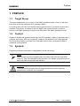
s SIMIT 7 OPC Gateway User Manual s Edition January 2013 Siemens offers simulation software to plan, simulate and optimize plants and machines. The simulation- and optimizationresults are only non-binding suggestions for the user. The quality of the simulation and optimizing results depend on the correctness and the completeness of the input data. Therefore, the input data and the results have to be validated by the user. Trademarks SIMIT® is a registered trademark of Siemens AG in Germany and in other contries. Other names used in this document can be trademarks, the use of which by third-parties for their own purposes could violate the rights of the owners. Copyright Siemens AG 2013 All rights reserved Exclusion of Liability The reproduction, transmission or use of this document or ist contents is not permitted without express written authority. Offenders will be liable for damages. All rights, including rights created by patent grant or registration of a utility model or design, are reserved. We have checked that the contents of this document correspond to the hardware and software described. However, deviations cannot be entirely excluded, and we do not guarantee complete conformance. The information contained in this document is, however, reviewed regularly and any necessary changes will be included in the next edition. We welcome suggestions for improvement. Siemens AG Industry Sector Industry Automation Division Process Automation SIMIT HB-V7OPC-2013-01-en Siemens AG 2013 Subject to change withour prior notice. s Contents 1 PREFACE 1 1.1 Target Group 1 1.2 Content 1 1.3 Symbols 1 2 FUNCTIONING OF THE OPC GATEWAY 2 3 THE OPC SERVER GATEWAY 3 3.1 4 3 3.2 Configuring I/O signals in the OPC Server gateway 3.2.1 Exporting and importing a signal table in ini-format 3.2.2 Importing a signal table in txt-format 4 5 6 3.3 Properties of the OPC Server gateway 7 3.4 Special features of the OPC Server gateway 3.4.1 Used data types 3.4.2 “Quality“ of a signal 3.4.3 OPC Server state 3.4.4 Changing an OPC-Servers configuration 7 7 8 8 8 THE OPC CLIENT GATEWAY 4.1 5 Creating an OPC Server gateway Creating an OPC Client gateway 10 10 4.2 Configuring I/O-signals in the OPC Client gateway 4.2.1 Exporting and importing a signal table in ini-format 4.2.2 Importing a signal table in txt-format 4.2.3 Configuration by querying the OPC Server 11 13 13 14 4.3 15 Properties of the OPC Client gateway 4.4 Signal properties within the gateway 4.4.1 Cycle multiplier 4.4.2 Mapping of data types 4.4.3 “Quality“ of a signal 17 17 18 18 4.5 Special features of the OPC Client gateway 4.5.1 Reading input signals 4.5.2 Establishing a connection to the OPC Server 20 20 20 DCOM CONFIGURATION 5.1 Firewall Copyright Siemens AG, 2013 Process Automation 22 22 SIMIT 7 - OPC Gateway Page I s 5.2 Domain and User 22 5.3 Granting access rights 22 Copyright Siemens AG, 2013 Process Automation SIMIT 7 - OPC Gateway Page II s List of Figures Figure 2-1: Typical OPC configuration 2 Figure 3-1: Adding an OPC Server gateway 3 Figure 3-2: Opening the OPC Server gateway in edit mode 4 Figure 3-3: Configuring the OPC Server gateway 5 Figure 3-4: Properties of the OPC Server gateway 7 Figure 3-5: OPC Server cannot be configured 9 Figure 4-1: Adding an OPC Client gateway 10 Figure 4-2: Opening the OPC Client gateway in edit mode 11 Figure 4-3: Configuring the OPC Client gateway 12 Figure 4-4: Properties within the OPC Client gateway that can be configured 15 Figure 4-5: OPC Client gateways properties view in running simulation 16 Figure 4-6: Quality signal in the properties view of a signal 18 Figure 4-7: Value of the quality signal within the properties view of the signal 19 Figure 4-8: Input signal that can be read 20 Figure 4-9: Usage of readable input signals 20 Figure 4-10: Messages concerning not reachable OPC Server 21 Figure 4-11: Messages concerning unknown OPC signals 21 Copyright Siemens AG, 2013 Process Automation SIMIT 7 - OPC Gateway Page III s List of Tables Table 3-1: Sections in the ini-format 5 Table 3-2: Interpretation of a signal table 6 Table 3-3: Mapping of data types 8 Table 4-1: Sections in the ini-format 13 Table 4-2: Interpretation of a signal table 14 Table 4-3: Mapping of data types 14 Table 4-4: Mapping of OPC access types 15 Table 4-5: Meaning of an OPC Servers status values 17 Table 4-6: Mapping of data types 18 Copyright Siemens AG, 2013 Process Automation SIMIT 7 - OPC Gateway Page IV s Preface 1 PREFACE 1.1 Target Group This manual addresses you as a user of the SIMIT simulation system. Here you will get to know how to use and handle an OPC gateway in SIMIT. As a prerequisite you need to be familiar with the general use of a personal computer and windows. Furthermore, knowlede of both the SIMIT basic system as well as common features of all SIMIT gateways is required, as described in the SIMIT gateways manual. 1.2 Content Chapter 2 explains the general functioning of an OPC gateway. Chapter 3 describes how to configure and use an OPC Server gateway, chapter 4 describes the OPC Client gateway. The concluding chapter 5 provides some information about how to configure DCOM for networked communication. 1.3 Symbols Particularly important information is highlighted in the text as follows: NOTE Notes contain important supplementary information about the documentation contents. They also highlight those properties of the system or operator input to which we want to draw particular attention. CAUTION This means that the system will not respond as described if the specified precautionary measures are not applied. Copyright Siemens AG, 2013 Process Automation SIMIT 7 - OPC Gateway Page 1 s Functioning of the OPC gateway 2 FUNCTIONING OF THE OPC GATEWAY OPC is a well-established standard for communication within automation technology and is maintained by the OPC Foundation (www.opcfoundation.org). In the OPC Classic Architecture an OPC DA Server is connected to a subordinate hardware layer. Signals originating from this hardware layer are made available via the local network to one or more OPC DA Clients (see Figure 2-1). Figure 2-1: Typical OPC configuration OPC Server and OPC Client may be running locally on the same PC or on different PCs. The OPC protocol can also be used to communicate data between programs that support OPC, independently from any hardware devices. With the OPC gateway SIMIT can be used both as OPC Server and as OPC Client. In both cases SIMIT supports the OPC standard v3.0 in “data access” mode (OPC DA 3.0). Within a SIMIT project, only one single OPC Server gateway can be used. The OPC Client gateway can be used in several instances, however. This allows for you to connect a single SIMIT simulation to several OPC Servers. You can also use one single OPC Server gateway and several OPC Client gateways simultaneously within a SIMIT project. Copyright Siemens AG, 2013 Process Automation SIMIT 7 - OPC Gateway Page 2 The OPC Server gateway s 3 THE OPC SERVER GATEWAY In this chapter you learn how to create and configure an OPC Server gateway within your SIMIT project and you also learn to know the properties and special features of this gateway. 3.1 Creating an OPC Server gateway In order to add an OPC Server gateway to your project, use the New Gateway command in the project tree. Choose OPC Server as gateway type (see Figure 3-1). Figure 3-1: Adding an OPC Server gateway In the SIMIT project you may assign an arbitrary name to your OPC Server gateway. To accept the default name, just press Enter. The gateway editor will now open automatically. By double clicking the gateway or by using the context menu you can open the editor at any time later (see Figure 3-2). Copyright Siemens AG, 2013 Process Automation SIMIT 7 - OPC Gateway Page 3 s Figure 3-2: 3.2 The OPC Server gateway Opening the OPC Server gateway in edit mode Configuring I/O signals in the OPC Server gateway The input and output signals of the OPC Server gateway can be edited manually in the editor or can be configured by importing a signal table (see Figure 3-3). For import just click the -button. Copyright Siemens AG, 2013 Process Automation SIMIT 7 - OPC Gateway Page 4 The OPC Server gateway s Figure 3-3: Configuring the OPC Server gateway 3.2.1 Exporting and importing a signal table in ini-format A signal table in ini-format contains six sections that are tagged with keywords as shown in Table 3-1. These keywords need to stand alone in a line. The subsequent lines contain names of signals that are to be associated to this section. Sections can be arranged in arbitrary order, it is not necessary to use all sections. Keyword Meaning [AIN] Analog input signals [IIN] Integer input signals [BIN] Binary input signals [AOUT] Analog output signals [IOUT] Integer output signals [BOUT] Binary output signals Table 3-1: Sections in the ini-format For every section the file contains a single line per signal. Signals are exported with their Copyright Siemens AG, 2013 Process Automation SIMIT 7 - OPC Gateway Page 5 The OPC Server gateway s name and comment written in double quotes and using the semicolon as separator: “Name”; “Comment” For the import the default value needs to be specified, too: “Name”; “Comment”; “Default” If a line contains a signal name only without any quotes, the signal will be imported using the specified name, the standard default value and without any comment. 3.2.2 Importing a signal table in txt-format SIMIT can store a gateway’s content in txt-format. This format contains SIMATIC addresses and information about standardization. Since this kind of information does not exist within an OPC gateway, the txt-format does not fully meet your needs here. However, you can still import signal tables in txt-format, only relevant information will be used in the OPC gateway. Column Name General meaning Meaning in the OPC gateway 1 Symbol Symbolic name of a signal (optional) Signal name, if provided 2 I/O Keys I, Q, IB, QB, IW, QW, ID, QD or in German notation (E/A) Distinction between input and output signals 3 Address Signals absolute address, e.g. 0.0 oder 512 Signal name (preceded by I/O), if no symbol provided 4 Type Signal data type: BOOL, BYTE, WORD, DWORD, INT, DINT or REAL BOOL: binary BYTE, WORD, DWORD: integer INT, DINT: integer REAL: analog 5 Comment Text as comment (optional) Comment 6 Lower Limit None 7 Upper Limit Lower and upper limit of analog signals: measurement range for input signals, boundary values for output signals 8 Standardization Type no. of standardization None 9 Unit Signal unit, e.g. physical unit for measured values None 10 Default value Initial value that is used as default value for this signal Default value 11 Cycle Definition of cycle multiplier n: None None Signal will be updated in every n-th cycle Table 3-2: Copyright Siemens AG, 2013 Process Automation Interpretation of a signal table SIMIT 7 - OPC Gateway Page 6 The OPC Server gateway s 3.3 Properties of the OPC Server gateway When the gateway is opened you see its editor. The properties view (see Figure 3-4) is used to define properties as follows: • Cycle Here you can define the cycle the gateway will use for data exchange. Use the project manager to assign absolute values to the eight available cycles throughout the project. The default value for cycle 2 is 100ms. For further detail concerning a gateways data exchange please see the general SIMIT gateway manual. • Server name Display of the SIMIT OPC servers name is for your information only. The server name always is “TSOPC-SDN DA Simit Server“. It cannot be changed. Server name or ProgID are required to configure an OPC Client to access this OPC Server. • ProgID Display of the SIMIT OPC servers ProgID is for your information only. The ProgID always is “OPCServer.Simit.7“. It cannot be changed. ProgID or server name are required to configure an OPC Client to access this OPC Server. • Use 64-bit integer In SIMIT integer values use 64 bit (8 byte) and are created accordingly in the OPC Server gateway. In case an OPC Client that is connected to this OPC Server cannot handle 64 bit integer values, please uncheck this option. SIMIT will then communicate all integer values with 32 bit (4 byte) only. Please note that this may lead to loss of data if a number cannot be represented using 32 bit only! Figure 3-4: 3.4 Properties of the OPC Server gateway Special features of the OPC Server gateway 3.4.1 Used data types In the OPC Server SIMIT will create signals with data types as listed in Table 3-3. Copyright Siemens AG, 2013 Process Automation SIMIT 7 - OPC Gateway Page 7 The OPC Server gateway s SIMIT data type OPC data type Binary BOOL Integer I8, if option “use 64-bit integer“ is checked I4 otherwise. Analog R8 Table 3-3: Mapping of data types As a consequence, the OPC Server will only provide data types BOOL, R8 and I8 or I4. 3.4.2 “Quality“ of a signal When the simulation is running, SIMIT communicates all OPC signals with quality “good, non-specific”, i.e. value 0xC0 (192 decimal). This value cannot be changed. When the simulation is closed, the OPC server remains active as long as there are OPC clients connected. In this case signal quality will be “bad, out of service”, i.e. value 0x1C. The quality value can be read by any connected OPC Client but is not displayed in the OPC Server gateway. 3.4.3 OPC Server state A connected OPC Client can query the server state. The server of SIMITs OPC Server gateway will return value 1 (running) as status when the simulation is running, value 4 (suspended) otherwise. 3.4.4 Changing an OPC-Servers configuration When the simulation is started the SIMIT OPC Server will automatically be configured with signals as defined in the OPC Server gateway. From then on an OPC Client can connect to the Server and access the signals. After the simulation is closed the OPC Server remains active as long as a minimum of one OPC Client is connected to it. Server state will change to OPC_STATUS_SUSPENDED, signal values will not be updated anymore and the signal’s quality will be set to “bad, out of service”, i.e. value 0x1C. When the simulation is started again the OPC Server will automatically be checked for modifications in its configuration. If the configuration has changed and there are still clients connected, the new configuration cannot be assigned. To avoid an inconsistent simulation state an error message is issued in this case (see Figure 3-5) and simulation will not be started. Copyright Siemens AG, 2013 Process Automation SIMIT 7 - OPC Gateway Page 8 s Figure 3-5: Copyright Siemens AG, 2013 Process Automation The OPC Server gateway OPC Server cannot be configured SIMIT 7 - OPC Gateway Page 9 The OPC Client gateway s 4 THE OPC CLIENT GATEWAY In this chapter you learn how to create and configure an OPC Client gateway within your SIMIT project and you also learn to know the properties and special features of this gateway. 4.1 Creating an OPC Client gateway In order to add an OPC Client gateway to your project, use the New Gateway command in the project tree. Choose OPC Client as gateway type (see Figure 4-1). Figure 4-1: Adding an OPC Client gateway In the SIMIT project you may assign an arbitrary name to your OPC Client gateway. To accept the default name, just press Enter. The gateway editor will now open automatically. By double clicking the gateway or by using the context menu you can open the editor at any time later (see Figure 4-2). Copyright Siemens AG, 2013 Process Automation SIMIT 7 - OPC Gateway Page 10 s Figure 4-2: 4.2 The OPC Client gateway Opening the OPC Client gateway in edit mode Configuring I/O-signals in the OPC Client gateway The input and output signals of the OPC Client gateway can be edited manually in the editor, can be configured by importing a signal table (see Figure 4-3), or can be configured by querying an accessible OPC Server. Copyright Siemens AG, 2013 Process Automation SIMIT 7 - OPC Gateway Page 11 s Figure 4-3: Copyright Siemens AG, 2013 Process Automation The OPC Client gateway Configuring the OPC Client gateway SIMIT 7 - OPC Gateway Page 12 The OPC Client gateway s 4.2.1 Exporting and importing a signal table in ini-format A signal table in ini-format contains six sections that are tagged with keywords as shown in Table 4-1. Keyword Meaning [AIN] Analog input signals [IIN] Integer input signals [BIN] Binary input signals [AOUT] Analog output signals [IOUT] Integer output signals [BOUT] Binary output signals Table 4-1: Sections in the ini-format These keywords need to stand alone in a line. The subsequent lines contain names of signals that are to be associated to this section. Sections can be arranged in arbitrary order, it is not necessary to use all sections. For every section the file contains a single line per signal. Signals are exported with their name, comment and cycle multiplier written in double quotes and using the semicolon as separator: “Name”; “Comment”; “Multiplier” For the import the default value needs to be specified, too: “Name”; “Comment”; “Default”; “Multiplier” If a line contains a signal name only without any quotes, the signal will be imported using the specified name, the standard default value and without any comment. 4.2.2 Importing a signal table in txt-format SIMIT can store a gateway’s content in txt-format (see Table 4-2). This format contains SIMATIC addresses and information about standardization. Since this kind of information does not exist within an OPC gateway, the txt-format does not fully meet your needs here. However, you can still import signal tables in txt-format, only relevant information will be used in the OPC gateway. Copyright Siemens AG, 2013 Process Automation SIMIT 7 - OPC Gateway Page 13 The OPC Client gateway s Column Name General Meaning Meaning in the OPC gateway 1 Symbol Symbolic name of a signal (optional) Signal name, if provided 2 I/O Keys I, Q, IB, QB, IW, QW, ID, QD or in German notation (E/A) Distinction between input and output signals 3 Address Signals absolute address, e.g. 0.0 oder 512 Signal name (preceded by I/O), if no symbol provided 4 Type Signals data type: BOOL, BYTE, WORD, DWORD, INT, DINT or REAL BOOL: binary BYTE, WORD, DWORD: integer INT, DINT: integer REAL: analog 5 Comment Text as comment (optional) Comment 6 Lower Limit None 7 Upper Limit Lower and upper limit of analog signals: measurement range for input signals, boundary values for output signals 8 Standardiza tion Standardizations type no. None 9 Unit Signals unit, e.g. physical unit for measured values None 10 Default value Initial value that is used as default value for this signal Default value 11 Cycle Definition of cycle multiplier n: Multiplier None Signal will be updated in every n-th cycle Table 4-2: Interpretation of a signal table 4.2.3 Configuration by querying the OPC Server SIMIT provides an easy way to transfer all signals from an OPC Server to your OPC Client gateway. First select the OPC Server from which signals are to be transferred in the OPC Client gateways properties – as shown in section 4.3. Then click the Browse button. All signals from the OPC server that can be mapped to a SIMIT data type (see Table 4-3) will be transferred into the OPC client gateway. OPC data type SIMIT data type BOOL, UI1 binary I1, I2, I4, I8, UI2, UI4, UI8 integer R4, R8 analog Table 4-3: Mapping of data types In case not all signals are required you can still manually delete signals from the gateways signal table. Copyright Siemens AG, 2013 Process Automation SIMIT 7 - OPC Gateway Page 14 The OPC Client gateway s Signals as provided by the OPC server can be readable, writeable or readWriteable and are treated in SIMIT as input or output (see Table 4-4). OPC SIMIT readable output writeable input readWriteable Input Table 4-4: 4.3 Mapping of OPC access types Properties of the OPC Client gateway When the gateway is opened you see its editor. The properties view (see Figure 4-4) is used define the cycle, host name, ProgID and state. Figure 4-4: Properties within the OPC Client gateway that can be configured These properties have meaning as follows: • Cycle Here you can define the cycle the gateway will use for data exchange. Use the project manager to assign absolute values to the eight available cycles throughout the project. The default value for cycle 2 is 100ms. For further detail concerning a gateways data exchange please see the general SIMIT gateway manual. • Host name Here you can specify on which PC the OPC Server this OPC Client should communicate with is running. You can provide either the PCs name or its IP-address. The default value is the local machine (localhost). • ProgID Specify the ProgId of the OPC Server that should be accessed on the machine depicted by hostname. If you use a local connection which means the hostname is “localhost”, you can select from a list of all ProgIDs of OPC Servers that can be accessed locally. Just select the OPC Server this gateway should communicate with. If you leave the ProgID not assigned there will be no connection established to any OPC Server when starting the simulation. In this case cyclic data exchange does not take place. Copyright Siemens AG, 2013 Process Automation SIMIT 7 - OPC Gateway Page 15 s • The OPC Client gateway Status display You can query the state of an accessed OPC Server when the simulation is running. Each OPC Client gateway provides a dedicated integer signal for that purpose, the name of which you can specify here. The signals default name is is_active. You may use this signal like any other output signal of any gateway in your SIMIT project and evaluate the servers state. When the simulation is running, the OPC Client gateways properties view will show the current state of the attached OPC Server (see Figure 4-5). Table 4-5 shows the meaning of possible state values 1. Figure 4-5: 1 OPC Client gateways properties view in running simulation NOTE It depends on the OPC Servers implementation which of the status values mentioned it actually provides. Information concerning status values 1 through 6 is taken from the specification “Data Access Custom Interface Standard, Version 3.00“. Copyright Siemens AG, 2013 Process Automation SIMIT 7 - OPC Gateway Page 16 The OPC Client gateway s Status value Meaning 0 No connection to the OPC Server 1 The server is running normally. This is the usual state for a server. 2 A vendor specific fatal error has occurred within the server. The server is no longer functioning. The recovery procedure from this situation is vendor specific. An error code of E_FAIL should generally be returned from any other server method. 3 The server is running but has no configuration information loaded and thus cannot function normally. Note this state implies that the server needs configuration information in order to function. Servers which do not require configuration information should not return this state. 4 The server has been temporarily suspended via some vendor specific method and is not getting or sending data. Note that Quality will be returned as OPC_QUALITY_OUT_OF_SERVICE. 5 The server is in Test Mode. The outputs are disconnected from the real hardware but the server will otherwise behave normally. Inputs may be real or may be simulated depending on the vendor implementation. Quality will generally be returned normally. 6 The server is running properly but is having difficulty accessing data from its data sources. This may be due to communication problems, or some other problem preventing the underlying device, control system, etc. from returning valid data. It may be complete failure, meaning that no data is available, or a partial failure, meaning that some data is still available. It is expected that items affected by the fault will individually return with a BAD quality indication for the items. Table 4-5: 4.4 Meaning of an OPC Servers status values 2 Signal properties within the gateway 4.4.1 Cycle multiplier Like any SIMIT gateway the OPC Client gateway will be executed cyclically. As usual you provide the cycle time via the cycle in the gateways properties view (see section 4.3). Since by definition the OPC gateway uses software layers (COM, DCOM) which may influence performance of signal exchange, you may use a cycle multiplier to adapt to your possibilities. A cycle multiplier of n leads to the corresponding signal to be communicated in every n-th cycle and not in every cycle any more. In order not to overcharge bandwidth of 2 Description of status values 1 through 6 is taken from the OPC specification Copyright Siemens AG, 2013 Process Automation SIMIT 7 - OPC Gateway Page 17 The OPC Client gateway s communication between OPC Server and OPC Client you may use a small cycle multiplier value for fast-changing signals and a large value for slowly changing signals. The default value is 1, i.e. each signal will be updated in each cycle. 4.4.2 Mapping of data types SIMIT only knows binary, integer and analog signals, with integer and analog signals using 64 bit (8 byte). An OPC Server may provide signals in several other data types. Table Table 4-6 shows how OPC data types are mapped to SIMIT data types. OPC SIMIT BOOL, UI1 binary I1, I2, I4, I8, UI1, UI2, UI4, UI8 integer R4, R8 analog Table 4-6: Mapping of data types For any output signal within the gateway there is no loss of data due to conversion, since both integer and analog signals in SIMIT use 64 bit (8 byte). 4.4.3 “Quality“ of a signal In addition to the signal value itself an OPC Server will communicate information about its quality. You can access this information within the simulation, since SIMIT automatically introduces an additional integer signal for any output signal in the OPC Client gateway. The name of this signal consists of the name of the original signal and the suffix .quality (see Figure 4-6) . Figure 4-6: Quality signal in the properties view of a signal Within the properties view of a signal in the OPC Client gateway you can observe the value of its corresponding quality signal when the simulation is running (see Figure 4-7). You may also use this quality signal like any other (integer) signal within your simulation. Input signals, i.e. signals that are communicated from the SIMIT OPC Client to the OPC Server, always are assigned quality “good, non-specific”, i.e. 0xC0 (192 decimal). This value cannot be changed. Copyright Siemens AG, 2013 Process Automation SIMIT 7 - OPC Gateway Page 18 s The OPC Client gateway NOTE Please note that quality signals are also only updated when there is a connection to the OPC Server. If in doubt please check the status display in the properties view of the OPC Client gateway. Figure 4-7: Copyright Siemens AG, 2013 Process Automation Value of the quality signal within the properties view of the signal SIMIT 7 - OPC Gateway Page 19 The OPC Client gateway s 4.5 Special features of the OPC Client gateway 4.5.1 Reading input signals Signals that are communicated from SIMIT to an OPC Server may not be accepted and taken over by the OPC Server. In your simulation you may need to use the value that actually is valid, so you can read input signals. Please not that this is possible only if the signal is declared as “readWritable” in the OPC Server. In order to be able to read an input signal, please check the corresponding option within its properties view (see Figure 4-8). Figure 4-8: Input signal that can be read You can then use the input signal in an output connector in order to read the value that is actually effective on the OPC Server side (see Figure 4-9). Figure 4-9: Usage of readable input signals 4.5.2 Establishing a connection to the OPC Server A connection to the OPC Server is established automatically upon starting the simulation. If no connection could be established with a timeout of 5 seconds, the simulation will start anyway and the connection will be established in background. If an already established connection breaks later, SIMIT will try and establish a new connection cyclically. In such cases the messaging system will keep you notified (see Figure 4-10). Copyright Siemens AG, 2013 Process Automation SIMIT 7 - OPC Gateway Page 20 s Figure 4-10: The OPC Client gateway Messages concerning not reachable OPC Server The current state of connection can be monitored using the status display (see section 4.3). After a connection is established to the OPC Server, SIMIT will try and register all signals as listed in the OPC Client gateway with the OPC Server. It may happen that a signal is unknown to the OPC Server or does not have the right data type. In this case the messaging system will keep you notified (see Figure 4-11). Figure 4-11: Copyright Siemens AG, 2013 Process Automation Messages concerning unknown OPC signals SIMIT 7 - OPC Gateway Page 21 s 5 DCOM configuration DCOM CONFIGURATION As long as both Server and Client are running on the same machine, an OPC connection is a local connection and does not require any special system settings. If a local network is used to establish an OPC connection between two different machines, some basic conditions need to be met. In this case DCOM is used, which will only work if configured properly. Since communication between different machines usually is controlled by a firewall, adequate settings are necessary here, too. NOTE All settings concerning access rights on your windows PC heavily depend on both version of your operating system and software that is installed already. Hence we can only provide hints about how to configure DCOM but not a detailed recipe with respect to your environment. CAUTION Apply changes to your machines settings only if you are aware of their consequences. Please take care not to unwillingly weaken your machines protection! 5.1 Firewall When using a firewall you need to allow incoming services for TCP port 135, which is used by DCOM. Furthermore all relevant OPC Servers and OPC Clients as well as Microsoft Management Console and OPCEnum must not be blocked. 5.2 Domain and User All relevant machines need to belong to the same work group or domain. Use the same user name and password on all machines. 5.3 Granting access rights When establishing an OPC connection via DCOM, a machine will access another machines ressources and launch certain processes on this machine. This needs to be explicitly enabled, since such action might possibly be dangerous to your machine. Both access rights as well as launch- and activation rights need to be properly set. Required rights can be granted to all users. It is more secure, however, to create a dedicated user group. This allows you to individually decide who should be member of this group and thus is Copyright Siemens AG, 2013 Process Automation SIMIT 7 - OPC Gateway Page 22 s DCOM configuration assigned further-reaching rights. In addition to general settings concerning COM security you need to set rights for both OPC Server and the helper tool OPCEnum.exe. For configuration use dcomcnfg.exe under Windows-XP and Windows-Vista. Details concerning DCOM configuration can e.g. be found in the document Using OPC via DCOM with Windows XP Service Pack 2 released by the OPC foundation and available in the internet via http://www.opcfoundation.org. Copyright Siemens AG, 2013 Process Automation SIMIT 7 - OPC Gateway Page 23