1
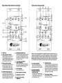
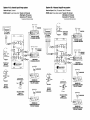
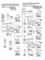
How this crossover is used Important features The Planet Audio EC20B 3-way elec tronic crossover is a high-fidelity signal processor that allows you to custom ize the low level output of your input source (e.g., a car radio), so that the signal can be applied to an amplifier or amplifiers as a part of a 2-way or 3-way mobile audio system. The EC20B incorporates several key fea tures which greatly expand the ways in which it can be used in a mobile audio system. It is intended for use in a car audio system which includes amplifiers in the signal path AFTER the crossover, and provides Front, Rear and Sub woofer LOW LEVEL outputs via RCA connectors. Product architecture This crossover accepts the low level (RCA type) input signal from the follow ing types of head unit outputs: a) 2-channel (UR) only b) Front (UR) and Rear c) Front (UR), Rear (UR) and Subwoofer channel (mono) d) Front (UR), Rear (UR) and Subwoofer channel (UR) By making proper switch settings, any of these types of head unit outputs can . be utilized as a signal source from which the EC20B can derive a few different kinds of system configurations. Exam ples of these are shown in diagrams in this manual. Turning on the power Before installing your new Planet Audio crossover, please become familiar with all the information contained in this manual. Before powering up for the first time: 1. Carefully check all electrical and audio connections. Parallel input selection The EC20B is optimized for head units which provide outputs for Front (UR), Rear (UR) and Subwoofer (UR) channels. But what if your head unit only provides a single pair of stereo (UR) outputs? By setting the Parallel Input selector con trol to OUT, the signal applied to the Front (UR) EC20B inputs will also be routed to the Rear channel. This eliminates the need for external y-adaptors, which can some times add noise to the system. Now you can provide custom processing to the Rear channel independent of the settings you apply to the front. Front channel crossoverlnuftipHer By providing a way for you to select a frequency from either a MidS/Highs range or a Tweeter range for the Front channel crossover, we give you the choice to use this crossover in different applications. For example, you can use the Front channel as a stereo Tweeter channel by setting the Crossover Frequency Multiplier to the high er 800Hz-8kHz range, and Rear channel can serve as the Mids/Highs channel - for a 3-way stereo system. Or you could create a 4-channel system, with Front and Rear channels reproducing the MidS/Hlghs. Subwoofer input mix option Many head units also lack a subwoofer channel output. In this situation, by setting the Sub Input control to MIX, the EC20B sub channel controls will be delivered a mix of L Front/Rear to the Subwoofer Left Channel and a mix of the R Front Rear to the Subwoofer Right channel This elimi nates the need for external Y adaptors and mixer devices. EC20B User's Manual· page 2 Installation Choose a mounting location where the unit will not distract or otherwise interfere with the driver's ability to control the vehicle. Use only the installation parts and hardware provided with the unit to ensure proper installation. Using other parts can. cause malfunction and possible damage to your Planet Audio crossover. Avoid installing the unit in a location which is subject to high temperatures, direct sunlight, hot air from such sources as heaters or exhaust lines, or where it will be subject to contact with dust, dirt, moisture or excessive vibration. Mounting the crossover The EC20B is designed to be installed securely to a flat surface in your vehicle using the screws and washers provided. Install the unit according to the diagram below. /~ ~~ Spring washer Flat washer 2. Set all level controls to their minimum positions. 3. Set all switches to the settings appropriate for your installation. The EC20B has intemai ON/OFF circuitry which responds to fuming ON or OFF the head unit ofyour car audio system. This requires that your head unit have a remote tum-on lead available on the rear panel (which ·most head units have). With this convenient remote tum-onIoff feature, you never have to WOn)' about turning off the power to the equalizer when you shut off the audio system. When you are confident all connections have been made correctly: 1. Power up your audio system by turning on the head unit. 2. Set the volume control on the head unit to about 3/4 volume, and adjust the input level control for each channel to just below the level of distortion. Further fine tuning of the controls on the EC20B and the input levels of the connected amplifiers may be necessary to obtain satisfactory results. If you are unsure about how to fine tune the system, please consult with your Planet Audio dealer. Input, output, remote and power connections Front and rear channel controls 1) (2 1 c=:J HIGH PASS CROSSOVER • PowER lEVEL 2 I'4RAHftIHP!.l'f HIGH PASS CROSSOVER stOPE 6 ladB ICDl 3 MiN-=-'",.w 4r------I-----Id . ®5 d IRii<l BAss BooST lMil )2 7S0 2~ 1~O 0 +12rl8 INN SUB Be 20B MAX :?:S :~:~~:::~e~;~~~i~:';O:';~V;; ::::::::::::::::~O~~~~~~t:~:.~I______-\ cCPlun(?t 1~1I~ c=:J CD POWER LED ® FRONT AND REAR LlR INPUTS Connect the outputs of your head units to these connections and be sure to place the Parallel Input selector in the IN position. If only front outputs are available, see "Paralle/lnput Switch, " below. @) o PARALLEL INPUT SELECTOR If your audio source only has one pair of RCA inputs, placing this switch in the OUT position allows the signal source connected to the front inputs to also be routed to the rear channel of the EC20B. SUB INPUT SOURCE SELECTOR If your audio source lacks a subwoofer output, placing this switch in the MIX position will apply a mix of the front and rear channel of each of the left and inputs to the EC20B sub channel EC20B User's Manual - page 4 ® +12V, GROUND AND REMOTE TURN-ON TERMINALS Use this control to select the highest frequency to be sent to the subwoofer channel. Choose a frequency between 32 Hz and 250Hz. FUSE CONNECTOR CD Use only fuse with 3A rating. ® FRONT AND REAR UR OUTPUTS ® SUBWOOFER UR OUTPUTS ® CONNECTOR REMOTE LEVEL CONTROL .,";8 MIN ;~e.~:.r~~'~:';o:';~v;;:::::::::::::: .~:~~~N;;~t~: cCp~n(?thll~ SUBWOOFER CHANNEL INPUT Connect the subwoofer channel of your head unit to these connectors and place the Sub Input selector in the DIRECT pOSition. If no sub channel outputs are available, see "Sub Input Source Source," above. 3 way. :::::::::::::::: c=:J ® -0M~~U( LEVEL ;~IN l~ 3~SO_A_A, ~~~ ®R --U-u, U U,.L®l ®R c=:J c=:J Please note: Since signa/ processing for Front and Rear Channels is nearly identical, only Front Channel controls are described here. The only difference between the controls for Front and Rear is that due to the addition of a crossover frequency multiplier selector on the Front Channel, the high pass crossover setting on the Front channel can be made in either the 40Hz-400Hz range or 800Hz-8kHz range, while the Rear channel high pass crossover is limited to the 40Hz-400Hz range only. This allows the Front Channel to be used as a crossover for either mids or tweeter range. CD HIGH PASS CROSSOVER @) Use this control to set the lowest frequency which will pass through the Front (or Rear) Channel of your system. ® HIGH PASS CROSSOVER FREQUENCY MULTIPLIER (Front channel only) This selector sets the frequency range for the high pass crossover. Choose the x1 position for 40Hz-400Hz range, or x20 for 800Hz-8kHz range. o CROSSOVER SLOPE Crossover slope determines how rapidly the dropoff in sound level, measured in decibels/octave, occurs at the frequency selected by the crossover. One octave is equal to one-half of the currently selected frequency. For example, if you set the crossover to 80Hz and the slope to 18dB, the level at 40Hz to be 18dB lower than at 80Hz. OUTPUT LEVEL CONTROL This control allows you to independently set the output level of the channel. EC20B User's Manual - page 5 Electrical and remote level controller connections Subwoofer channel controls Using 16GA mininum wire connect the EC20B as follows: c:::::J c:::::J a. Connect the shortest possible wire to a clean, unpainted chassis ground point. Connect this wire to the Ground connection of the EC20B. 1 1 b. Connect the +12V terminal directly to the vehicle battery, using a distribution block near the crossover, if desired. Be sure to install a 3A inline fuse within 18 inches of the battery terminal. c. Connect the Remote terminal of the EC20B to the remote turn on lead from your head unit. c::::::J a c::::::J FREQUENCY FRONTIN ®L __ ®R""" I 40 • OUT . ~oo IN HIGH PASS CROSSOVER: ~ 01." T []I ~",;idB lEVEL [FUSE3A SUe SUB IN ®u~ FRONT Ill"" .,~ fi<£QUENCf SUBWOOF••CRoSSOV£MS[" MAA ®R r""'" R DliMoI)£ I'i'iiQ BAss SoosT::.;;T ;m;:l ~~~ R to REMOTE TURN-ON terminal of head unit ®RL ® o Cl 3A FUSE CD LOW PASS CROSSOVER Use this control to set the highest frequency which will pass through the Subwoofer Channel of your system. @ @ CD This OUTPUT LEVEL CONTROL control allows you to independently set the @) BASS BOOST FREQUENCY SELECTOR BASS BOOST LEVEL SELECTOR These two controls are used together to help you fine tune the bass boost added to the Subwoofer Channel signal. The Frequency Selector is used to identify the center frequency for the boost (Le., where the Bass Boost effect will be most pronounced). The Boost Level is used to set how much the level is increased around that frequency, up to +12dB. EC20B User's Manual· page 6 ~~p~n~t~u~ output level of the channel. @) PHASE SELECTOR Use this switch to select the output phase of the Subwoofer channel to provide the best time alignment and stereo imaging for your system. SUBWOOFER CHANNEL OUTPUT MODE If your system only includes one subwoofer, you will probably want this to receive a mono signal derived from the UR input signal. In this case, place the switch in the MONO position. For dual subwoofer systems, the choice of mono or stereo subwoofers is a matter of personal taste, although the directionality of low frequency signals is difficult for the human ear to detect, so the difference between the switch settings may be inaudible. ) , c::::::J c::::::J Cl IBattery I [][] Remote Subwoofer Level Control Input and output connections Input and output connections vary depending on the system application. Examples are shown in system diagrams on the pages which follow in this manual. Always use high quality RCA cables for input and output connections. EC20B User's Manual - page 7 System #1: 2 channel inputl3-way system System #2: 4 channel inputl3-way system Head unit input: 2 channel EC20B output: 3-way stereo system: Tweeter LlR channels Midslhighs LIR channels Subwoofer LlR* channels Head unit input: Front LlR channels, Rear LlR channels EC20B output: 3-way stereo system: Tweeter LlR channels Midslhighs LlR channels Subwoofer LIR* channels • can also be set to Mono Sub channel • can also be set to Mono Sub channel "fU 101 I To UR output from head unit tL -+0 4vl.. OUT IN c:::::J c:::::J TWEETER CHANNEL 2 CHANNEL AMPLIFIER ~ ~MIDRANGE If If SPEAKERS ~ UT ~y7W~ETERS II .... t::::lI=lI=lI::::lI=II:::l -4vl". IN c=I) To Front and Rear URoutputs from head unit tL PARAll Parallel Input Selector in IN position FREQUENC" c:::::J c:::::J TWEETER CHANNEL 2 CHANNEL AMPLIFIER ~ If Y MIDRANGE SPEAKERS FREQUENCV Parallel Input Selector in OUT position <CPl~<"thI4OJ c:::::J ..u ~_~h~]) c:::::J ~4lll... c:::::J (-SUB c:::::J ..0 ~4lJ\.. '--tINPUT I-SUB DIRECT '--tINPUT JBWOOFER CROSS rSTEREO 'HASE Sub Input Selector in MIX position 11111111 II Mor MONOBLOCK SUBWOOFER AMPLIFIER FOR LEFT CHANNEL JBWOOFER CROSS rSTEREO MONO ~"ST 'HASE !;:;:: Sub Channel Mode Selector In STEREO position "'---JSUBWOOFER T MONOBLOCK SUBWOOFER AMPLIFIER FOR RIGHT CHANNEL EC20B' User's Manual - page 8 DIRECT Sub Input Selector in MIX position ~MO[ MONOBLOCK SUBWOOFER AMPLIFIER FOR LEFT CHANNEL !!:t .... f)ST~ Sub Channel Mode Selector in STEREO position MONOBLOCK SUBWOOFER AMPLIFIER FOR RIGHT CHANNEL System #4: 4 channel Input/Dual crossover 3-way system System #3: 4 channel + 2 channel sub Input/3-way system Head unit input: Front LlR channels, Rear LlR channels, Subwoofer LlR channels EC20B output: 3-way stereo system: Tweeter LIR channels Midslhighs LIR channels Subwoofer LlR'" channels • can also be set to Mono Sub channel .+\J --- 1 t::::tt::JCJCJCJ~ To Rear LlR outputs from head unit 4ul.. r~l- To Front, Rear and Subwoofer LlR outputs from head unit 01 1 Head unit input: Front LlR channels, Rear LlR channels EC20B output: Dual 3-way stereo system: FRONT and REAR Tweeter LIR channels FRONT and REAR Mids/highs LIR channels FRONT and REAR Subwoofer LIR* channels FREQUENCV To Front LlR outputs from head unit FRONT SYSTEM tL Parallel Input Selector in IN position ~ ~ • can also be set to Mono Sub channel I ~ TWEETER CHANNEL 2 CHANNEL AMPLIFIER ~MIDRANGE IT TWEETER CHANNEL 2 CHANNEL AMPLIFIER SPEAKERS Paralfellnput Selector In OUT position ..v .......... 4 .... ~ [-SUI! "'--,lHPUT ~D'RE<T ~c.n<>tJ;~ ~ ~ FREQUENCY Sub Channel Mode Selector in STEREO position Sub Input Selector in MIX position ~c~~ ,..; -4\"~ ~ ~ ~ REAR SYSTEM ~ ...o-4v.. AA JBWOOFER CROSS 'HAsE Sub Input Selector in DIRECT position MONOBLOCK SUBWOOFER AMPLIFIER FOR LEFT CHANNEL SUBWOOFER 2 CHANNEL AMPLIFIER ~ ;~:;;;oop~c-QY£Il :n""- r_~ "''"~~~."",I ~t'''1 '~' fIIIi~C'f ""'" 1"'-' "" lEVEl DIll.... ®I!~- " SU81'100FEIt(ROSSovt~ MI. $\III iIQ'". M" ,_ ~!llY filnMoM 1iii><itw;$8ocSTTi\iO:1 -'1 <;t--" ,:,, FUSE» ovr ®l @R , ~ "0" 0"-0 e ,"m <IOI,:::!;:f "'\t')ST~ -"'1ST~ --i:'i--iCr-'::1"': : Paralle/lnput Selector in OUT position DIRECT J"WOOFEO C.oss 'HAs. Uvn ,,,. 0"' ®L @R s" ~ .,"'-:-"'• ..i.L:L~ EC 20B" ,3,;,~;:~",:,:~," ........ " ."" '~'El"::'I!I" Sub Channel Mode Selector in STEREO position 1'9:(~~~~t~ "_I!'ib _ _ ~ ~ • MONOBLOCK SUBWOOFER AMPLIFIER FOR RIGHT CHANNEL Sub Input Selector in MIX position ~ J"WOOFER COOS5 'HA,,, Iliifi°Mor ::r Sub Channel Mode Selector In STEREO position SUBWOOFER 2 CHANNEL AMPLIFIER "i)ST~ EC20B User's Manual - page 11 EC20B User's Manual - page 10 PLANET AUDIO SPEAKERS SPEAKER SYSTEMS