1
User's
Manual
IR200
Infrared Gas Analyzer
IM 11G02M01-01E
IM 11G02M01-01E
3rd Edition
PREFACE
We are grateful for your purchase of Yokogawa’s Infrared Gas Analyzer (Model : IR200).
• First read this instruction manual carefully until an adequate understanding is acquired, and
then proceed to installation, operation and maintenance of the analyzer. Wrong handling
may cause an accident or injury.
• The specifications of this analyzer are subject to change without prior notice for further
product improvement.
• Modification of this analyzer is strictly prohibited unless a written approval is obtained
from the manufacturer. Yokogawa will not bear any responsibility for a trouble caused by
such a modification.
• This instruction manual shall be stored by the person who actually uses the analyzer.
• After reading the manual, be sure to store it at a place easier to access.
• This instruction manual should be delivered to the end user without fail.
Manufacturer:
Yokogawa Electric Corporation.
Type:
Described in Yokogawa’s company nameplate on main frame
Date of manufacture: Described in Yokogawa’s company nameplate on main frame
Product nationality:
Japan
Request
• It is prohibited to transfer part or all of this manual without
Yokogawa’s permission.
• Description in this manual is subject to change without prior
notice for further improvement.
IM 11G02M01-01E
i
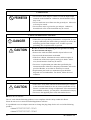
CAUTION ON SAFETY
First of all, read this “Caution on safety” carefully, and then use the analyzer in the correct way.
• The cautionary descriptions listed here contain important information about safety, so they should
always be observed. Those safety precautions are ranked in 3 levels, “DANGER”, “CAUTION” and
“PROHIBITION”.
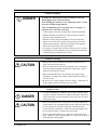
DANGER
Wrong handling may cause a dangerous situation, in which
there is a risk of death or heavy injury.
CAUTION
Wrong handling may invite a dangerous situation, in which
there is a possibility of medium-level trouble or slight injury or
only physical damage is predictable.
PROHIBITION
Items which must not be done are noted.
Caution on installation and transport of gas analyzer
DANGER
• This unit is not explosion-proof type. Do not use it in a place
with explosive gases to prevent explosion, fire or other
serious accidents.
CAUTION
• For installation, observe the rule on it given in the instruction
manual and select a place where the weight of gas analyzer
can be endured.
Installation at an unsuited place may cause turnover or fall and
there is a risk of injury.
• For lifting the gas analyzer, be sure to wear protective gloves.
Bare hands may invite an injury.
• Before transport, fix the casing so that it will not open. Otherwise, the casing may be separated and fall to cause an injury.
• During installation work, care should be taken to keep the unit
free from cable chips or other foreign objects. Otherwise, it
may cause fire, trouble or malfunction of the unit.
ii
IM 11G02M01-01E
Caution on piping
DANGER
In piping, the following precautions should be observed.
Wrong piping may cause gas leakage.
If the leaking gas contains a toxic component, there is a risk
of serious accident being induced.
Also, if combustible gas is contained, there is a danger of
explosion, fire or the like occurring.
• Connect pipes correctly referring to the instruction manual.
• Exhaust should be led outdoors so that it will not remain in
the locker and installation room.
• Exhaust from the analyzer should be relieved in the atmospheric air in order that an unnecessary pressure will not be
applied to the analyzer. Otherwise, any pipe in the analyzer
may be disconnected to cause gas leakage.
• For piping, use a pipe and a pressure reducing valve to which
oil and grease are not adhering. If such a material is adhering,
a fire or the like accident may be caused.
Caution on wiring
CAUTION
• Wiring work must be performed with the main power set to
OFF to prevent electric shocks.
• Enforce construction of class-D grounding wire by all means.
If the specified grounding construction is neglected, a shock
hazard or fault may be caused.
• Wires should be the proper one meeting the ratings of this
instrument. If using a wire which cannot endure the ratings, a
fire may occur.
• Be sure to use a power supply of correct rating. Connection of
power supply of incorrect rating may cause fire.
Caution on use
DANGER
CAUTION
• For correct handling of calibration gas or other reference gases,
carefully read their instruction manuals beforehand. Otherwise,
carbon monoxide or other hazardous gases may cause an intoxication particularly.
• Before leaving unused for a long time or restarting after left at
such a status for an extended length of time, follow the directions
of each instruction manual because they are different from
normal starting or shutdown. Otherwise, the performance may
be poor and accidents or injuries may be caused.
• Do not operate the analyzer for a long time with its door left
open. Otherwise, dust, foreign matter, etc. may stick on internal
walls, thereby causing faults.
IM 11G02M01-01E
iii
Caution on use
PROHIBITION
• Do not allow metal, finger or others to touch the input/output
terminals in the instrument. Otherwise, shock hazard or injury
may occur.
• Do not smoke nor use a flame near the gas analyzer. Otherwise,
a fire may be caused.
• Do not allow water to go into the gas analyzer. Otherwise,
hazard shock or fire in the instrument may be caused.
Caution on maintenance and check
DANGER
CAUTION
• When doors are open during maintenance or inspection, be sure
to purge sufficiently the inside of the gas analyzer as well as the
measuring gas line with nitrogen or air, in order to prevent
poisoning, fire or explosion due to gas leak.
Be sure to observe the following for safe operation avoiding
the shock hazard and injury.
• Remove the watch and other metallic objects before work.
• Do not touch the instrument wet-handed.
• If the fuse is blown, eliminate the cause, and then replace it
with the one of the same capacity and type as before. Otherwise, shock hazard or fault may be caused.
• Do not use a replacement part other than specified by the
instrument maker. Otherwise, adequate performance will not be
provided. Besides, an accident or fault may be caused.
• Replacement parts such as a maintenance part should be
disposed of as incombustibles. For details, follow the local
ordinance.
Others
CAUTION
iv
• If the cause of any fault cannot be determined despite reference
to the instruction manual, be sure to contact your dealer or Fuji
Electric’s technician in charge of adjustment. If the instrument is
disassembled carelessly, you may have a shock hazard or injury.
IM 11G02M01-01E
r After - Sales Warranty
d Do not modify the product.
d During the warranty period, for repair under warranty carry or send the product to
the local sales representative or service office. Yokogawa will replace or repair any
damaged parts and return the product to you.
d Before returning a product for repair under warranty, provide us with the model
name and serial number and a description of the problem. Any diagrams or data
explaining the problem would also be appreciated.
d If we replace the product with a new one, we won’t provide you with a repair report.
d Yokogawa warrants the product for the period stated in the pre-purchase quotation.
Yokogawa shall conduct defined warranty service based on its standard. When the
customer site is located outside of the service area, a fee for dispatching the
maintenance engineer will be charged to the customer.
d In the following cases, customer will be charged repair fee regardless of warranty
period.
• Failure of components which are out of scope of warranty stated in instruction
manual.
• Failure caused by usage of software, hardware or auxiliary equipment, which
Yokogawa did not supply.
• Failure due to improper or insufficient maintenance by user.
• Failure due to misoperation, misuse or modification which Yokogawa does not
authorize.
• Failure due to power supply (voltage, frequency) being outside specifications or
abnormal.
• Failure caused by any usage out of scope of recommended usage
• Any damage from fire, earthquake, a storm and flood, lightning, disturbance, riot,
warfare, radiation and other natural changes.
d Yokogawa does not warrant conformance with the specific application at the user
site. Yokogawa will not bear direct/indirect responsibility for damage due to a
specific application.
d Yokogawa will not bear responsibility when the user configures the product into
systems or resells the product.
d Maintenance service and supplying repair parts will be covered for five years after
the production ends. For repair this product, please contact the nearest sales office
described in this instruction manual.
IM 11G02M01-01E
v
CONTENTS
PREFACE.............................................................................................................................. i
CAUTION ON SAFETY .................................................................................................... ii
r After - Sales Warranty ................................................................................................... v
1. OVERVIEW ................................................................................................................. 1-1
2. NAME AND DESCRIPTION OF EACH PART ..................................................... 2-1
2.1
Description of each unit .................................................................................. 2-1
3. INSTALLATION ......................................................................................................... 3-1
3.1
3.2
3.3
3.4
3.5
Selection of installation location .....................................................................
Installation of analyzer ....................................................................................
Piping ...............................................................................................................
Sampling ..........................................................................................................
Wiring method ................................................................................................
3-1
3-2
3-2
3-3
3-6
4. OPERATION ............................................................................................................... 4-1
4.1
4.2
Preparation for operation ................................................................................ 4-1
Warm-up operation and regular operation ...................................................... 4-1
5. DESCRIPTION OF DISPLAY AND OPERATION PANELS .............................. 5-1
5.1
5.2
5.3
5.4
Name and description of operation panel .......................................................
Overview of display and operation panel .......................................................
Overview of display screen .............................................................................
General operation ............................................................................................
5-1
5-2
5-3
5-6
6. SETTING AND CALIBRATION .............................................................................. 6-1
6.1
6.2
Changeover of range ....................................................................................... 6-1
Calibration setting ........................................................................................... 6-2
6.2.1 Setting of calibration concentration ........................................................ 6-2
6.2.2 Setting of calibration gas ......................................................................... 6-4
6.2.3 Setting of manual zero calibration .......................................................... 6-6
6.2.4 Setting of calibration range ..................................................................... 6-8
6.2.5 Setting of auto-calibration component .................................................. 6-10
6.3 Alarm setting ................................................................................................. 6-12
6.3.1 Setting of alarm values .......................................................................... 6-12
6.3.2 Hysteresis setting ................................................................................... 6-14
6.4 Setting of auto calibration ............................................................................. 6-15
6.4.1 Auto calibration ..................................................................................... 6-15
6.4.2 Forced stop of auto calibration ............................................................. 6-17
6.5 Setting of auto zero calibration ..................................................................... 6-19
6.5.1 Auto zero calibration ............................................................................. 6-19
6.5.2 Forced stop of auto zero calibration ..................................................... 6-21
6.6 Peak alarm setting ......................................................................................... 6-23
6.7 Parameter setting ........................................................................................... 6-25
6.8 Maintenance mode ........................................................................................ 6-29
6.9 Calibration ..................................................................................................... 6-32
6.9.1 Zero calibration ..................................................................................... 6-32
6.9.2 Span calibration ..................................................................................... 6-33
vi
IM 11G02M01-01E
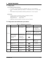
7. MAINTENANCE ......................................................................................................... 7-1
7.1
7.2
7.3
7.4
7.5
Daily check ......................................................................................................
Daily check and maintenance procedures ......................................................
Replacement of power fuse.............................................................................
Moisture interference compensation adjustment ............................................
Cleaning of measuring cell .............................................................................
7.5.1 Disassembly and assembly of measuring cell ........................................
7.5.2 How to clean cell .....................................................................................
7.6
Inspection and maintenance of limited service-life components ...................
7-1
7-1
7-2
7-3
7-4
7-4
7-9
7-9
8. TROUBLESHOOTING .............................................................................................. 8-1
8.1
8.2
Error message .................................................................................................. 8-1
Other Troubleshooting .................................................................................... 8-3
9. SPECIFICATIONS ...................................................................................................... 9-1
9.1
9.2
9.3
Specifications .................................................................................................. 9-1
Model and Suffix codes .................................................................................. 9-5
External Dimensions .................................................................................... 9-10
Customer Maintenance Parts List ............................................... CMPL 11G02M01-01E
Revision Record .................................................................................................................... i
IM 11G02M01-01E
vii
1. OVERVIEW
The infrared gas analyzer (IR200) measures the concentrations of CO2, CO, CH4, SO2, NO and O2
contained in sample gas.
CO2, CO, CH4, SO2, and NO are measured by non-dispersion infrared method, while O2 is measured by
paramagnetic or fuel cell method. Up to 4 components including O2 (3 at the maximum for measurement
of components other than O2) can be measured simultaneously.
A high-sensitivity mass flow sensor is used in the detector unit of infrared method. Due to use of single
beam system for measurement, maintenance is easy and an excellent stability is ensured for a long period
of time.
In addition, a microprocessor is built in and a large sized liquid crystal display is provided for easier
operation, higher accuracy and more functions.
This analyzer is thus optimum for combustion control of various industrial furnaces, botanical study and
global atmospheric research.
IM 11G02M01-01E
1-1
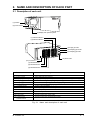
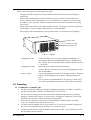
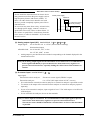
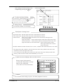
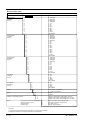
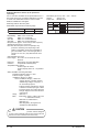
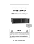
2. NAME AND DESCRIPTION OF EACH PART
2.1 Description of each unit
INFRARED GAS ANALYZER
POWER
(1) Handle
(2) Power switch
MODE
ESC
ZERO
ENT
SPAN
(3) Display and operation panel
(11) Terminal block 5
(10) Terminal block 4
(6) Purge gas inlet
(5) Sampling gas outlet
(4) Sampling gas inlet
(12) Power inlet
(13) Connector 2
(7) Terminal block 1
(8) Terminal block 2
(9) Terminal block 3
Name
(1)
(2)
(3)
(4)
(5)
(6)
(7)
(8)
(9)
(10)
(11)
(12)
(13)
Handle
Power switch
Display/Operation panel
Sampling gas inlet
Sampling gas outlet
Purge gas inlet
Terminal block 1
Terminal block 2
Terminal block 3
Terminal block 4
Terminal block 5
Power inlet
Connector for
communication
Description
Draws the analyzer unit from the case.
Turns ON/OFF this analyzer.
Liquid crystal display and keys for various operational settings are arranged.
Port for connecting the sample gas injection pipe
Port for connecting the pipe for discharging the gas after analysis
Port for connecting the purge gas pipe
Analog output terminals
O2 analyzer signal and contact input terminals
Contact input/output terminals
Contact output terminal
Alarm output terminal
Used to connect the power cable.
Used to connect the communication cable.
Fig. 2-1 Name and description of each unit
IM 11G02M01-01E
2-1
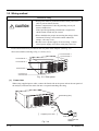
3. INSTALLATION
DANGER
This unit is not explosion-proof type. Do not use it in a place with explosive gases to prevent
explosion, fire or other serious accidents.
CAUTION
• For installation, observe the rule on it given in the instruction manual and select a place
where the weight of gas analyzer can be endured.
Installation at an unsuited place may cause turnover or fall and there is a risk of injury.
• For lifting the gas analyzer, be sure to wear protective gloves. Bare hands may invite an
injury.
• Before transport, fix the casing so that it will not open. Otherwise, the casing may be separated and fall to cause an injury.
• The gas analyzer is heavy. It should be transported carefully by two or more persons if
manually required. Otherwise, body may be damaged or injured.
• During installation work, care should be taken to keep the unit free from cable chips or other
foreign objects. Otherwise, it may cause fire, trouble or malfunction of the unit.
3.1 Selection of installation location
To install the analyzer for optimum performance, select a location that meets the following conditions;
(1) Use this instrument indoors.
(2) A vibration-free place
(3) A place which is clean around the analyzer.
(4) Power supply
Voltage rating
;100 V AC to 240 V AC
Allowable range
; 85 to 264 V AC
Frequency
; 50 Hz / 60 Hz
Power consumption; 70 VA max.
Inlet
; Conform to EN60320
Protection Class 1
(5) Operation conditions
Ambient temperature
: -5 to 45°C
Ambient humidity
: 90% RH or less, no condensation
IM 11G02M01-01E
3-1
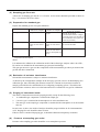
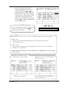
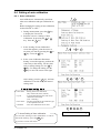
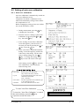
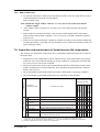
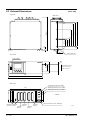
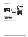
3.2 Installation of analyzer
There are two methods of installing the analyzer.
For detailed dimensions, see Chapter 9.3.
(Unit:mm)
19 inch rack mounting (Note)
Types
External dimensions
Mounting dimensions
Mounting method
Guide rail
MODE
ENT
Slide rail
M6
ZERO
ESC
SPAN
429
450 or more
483
465
101.6
177
INFRARED GAS ANALYZER
POWER
Guide rail
Slide rail
Note) The mounting method should be selected to meet the installation requirements since the top
cover must be detached from the gas analyzer for maintenance and check.
Mounting method
Remarks
Conditions
Slide rail
No maintenance space is provided at the top.
Guide rail
Maintenance space is provided at the top.
These methods must be rigid enough to
withstand the mass (about 10 kg) of the gas
analyzer.
Recommended slide rail: 305A-20, Accuride International Inc.
3.3 Piping
Caution on piping
CAUTION
In piping, the following precautions should be observed.
Wrong piping may cause gas leakage.
If the leaking gas contains a toxic component, there is a risk of
serious accident being induced.
Also, if combustible gas is contained, there is a danger of
explosion, fire or the like occurring.
• Connect pipes correctly referring to the instruction manual.
• Exhaust should be led outdoors so that it will not remain in
the locker and installation room.
• Exhaust from the analyzer should be relieved in the atmospheric air in order that an unnecessary pressure will not be
applied to the analyzer. Otherwise, any pipe in the analyzer
may be disconnected to cause gas leakage.
• For piping, use a pipe and a pressure reducing valve to which
oil and grease are not adhering. If such a material is adhering,
a fire or the like accident may be caused.
3-2
IM 11G02M01-01E
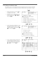
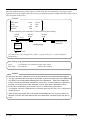
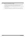
Observe the following when connecting the gas pipes.
•
The pipes should be connected to the gas inlet and outlet at the rear panel of the analyzer,
respectively.
•
Connect the sampling system to the instrument by using corrosion-resistant tube such as
Teflon, stainless steel, or polyethylene. In case where there is no danger of corrosion, don't
use rubber or soft vinyl tube. Analyzer indication may become inaccurate due to the adsorption of gases.
•
Piping connections are Rc1/4 (1/4 NPT) female-threaded. Cut the pipe as short as possible for
quick response. Pipe of ø 4mm (inside diameter) is recommendable .
•
Entry of dust in the instrumant may cause operation fault. Use clean pipes and couplings.
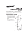
Purge gas inlet
Sampling gas outlet
Sampling gas inlet
Fig. 3-1 Piping
Sampling gas inlet:
Connect the pipe so that zero/span calibration standard gas or
measured gas pretreated with dehumidification is supplied properly. The gas flow rate should be kept constant within the range of
1 ± 0.5L/min.
Sampling gas outlet:
Measured gas is exhausted after measurement.
Connect the pipe so that the gas may escape through the gas outlet
into the atmosphere.
Purge gas inlet:
It is used for purging the inside of the total gas analyzer. When the
analyzer must be purged, refer to Item 3.4, Purging inside Analyzer.
Use dry gas N2 or instrumentation air for purge gas. (flow rate of
1L/min or more should be used and no dust or mist is contained).
3.4 Sampling
(1) Conditions of sample gas
1.
The dust contained in sample gas should be eliminated completely with filters. The filter at
the final stage should be capable of eliminating dust of 0.3 microns.
2.
The dew point of sample gas must be lower than the ambient temperature for preventing
formation of drain in the analyzer. If water vapor is contained in sample gas, its dew point
should be reduced down to about 0°C through a dehumidifier.
3.
If SO3 mist is contained in sample gas, the mist should be eliminated with a mist filter,
cooler, etc. Eliminate other mist in the same way.
4.
If a large amount of highly corrosive gas such as Cl2, F2 or HCl is contained in sample gas,
the service life of analyzer will be shortened. So, avoid such gases.
5.
Sample gas temperature is allowed within a range from 0 to 50°C. Pay attention not to flow
hot gas directly into the analyzer.
IM 11G02M01-01E
3-3
(2) Sampling gas flow rate
A flow rate of sampling gas must be 1 ± 0.5L/min. A flow meter should be provided as shown in
Fig. 3-2 to measure flow rate values.
(3) Preparation for standard gas
Prepare the standard gas for zero/span calibration.
Without O2 Analyzer
Zero gas
N2 gas
N2 gas
Span gas except for O2 Gas with concentration Gas with concentration
of 90% or more of full
of 90% or more of full
scale
scale
Span gas for O2
Externally mounted
zirconia O2 Analyzer
Built in O2 Analyzer
Dry air, air or gas in
concentration of 80% or higher
of the O2 range (CO2 should not
be contained in zero gas if CO2
meter is provided.)
Gas with concentration of 90%
or more of full scale
Gas with concentration 1 to 2% O2 gas
of 90% or more of full
scale or atmospheric air
(21%)
* We recommend you to feed the zero gas shown above by humidifying it, if NO or SO2 is included in
components to be analyzed.
(Note)
It is understood to influence the calibration model of the infrared gas analyzer when a lot of H2 ,
He, and Ar are included in the measurment gas (pressure broadening).
The span gas must use a gas near the composition of the measurement gas when you measure the
gas like the above-mentioned.
(4) Reduction of moisture interference
NO and SO2 measurement is subject to moisture interference.
As shown by the configuration example on the next page, provide a device for humidifying zero
calibration gas, thus controlling the moisture content at a constant level (moisture content in
sample gas should also be controlled here) in configuring a sampling system. That allows the
same moisture content as in the case of measurement to be contained in zero gas for calibration.
(5) Purging of instrument inside
The inside of instrument need not be purged generally except for the following cases.
1.
A combustible gas component is contained in sample gas.
2.
Corrosive gas is contained in the atmospheric air at the installation site.
3.
The same gas as the sample gas component is contained in the atmospheric air at the installation site.
In such cases as above, the inside of analyzer should be purged with the air for instrumentation
or N2. Purging flow rate should be about 1L/min.
If dust or mist is contained in purging gas, it should be eliminated completely in advance.
(6)
Pressure at sampling gas outlet
Pressure at the sampling gas outlet should be set to atmospheric pressure.
3-4
IM 11G02M01-01E
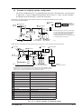
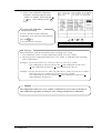
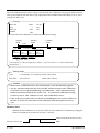
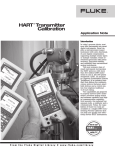
(7)
Example of sampling system configuration
The system configuration may vary depending upon the nature of measured gas, coexistent gases
or application. A typical configuration diagram is shown in Fig. 3-2. Since a system configuration depends upon measured gas, consult with Yokogawa.
Measurement of sample gas with low moisture content (room-temperature saturation level or below):
CO, CO2 and CH4 measurement
10 Secondary
Sample
gas inlet
7 4-way selector
3 Pump
External
O2 analyzer
Exhaust
(atmospheric
pressure)
cock
9 Flow meter
p 4 Electronic
dehumidifier
p
Gas
analyzer
(IR200)
filter
1 Primary filter
p A dehumidifier must be used for CO (0-200 ppm)
and SO2 measurements (to prevent saturation at
28C). Even in any other gas measurements, if
sample gas has a high moisture content or if
condensation is likely to occur, a safety drain trap
and a dehumidifier should be used.
2 Safety
drain
trap 5 Drain
pot
8
Standard gas
for zero calibration
Drain
6 Ball valve
Standard gas for
span calibration
F03.EPS
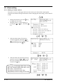
Measurement of sample gas with high moisture content or NO, SO2, or CO (0-200 ppm range) measurement
Primary filter
1
Flow meter
9
12
3
Pump
14
p
3
Pump
Solenoid
valve
11
Atmosphere
4
2
Safety
dran trap
14
Solenoid
valve
8
Secondary filter
13
NO2/NO
converter
14
Electronic
dehumidifier
14
Solenoid
valve
Bubbler
Gas analyzer
(IR200)
5
p
10
3-way
solenoid valve
Drain
pot
External O2
analyzer
Standard gas
for zero calibration
6
Drain
8
Ball valve
Standard gas
for span calibration
Exhaust
(atmospheric pressure)
p A dehumidifier must be used for NO, SO2, and CO (0-200 ppm) measurements (to prevent
saturation at 28C). Use either atmospheric air or cylinder gas as a zero calibration gas and
supply it through a bubbler (humidifying) to reduce interference of water.
No.
Description
Item
1
Primary filter (mist filter)
Remove dust and mist
2
Safety drain trap
Separate and discharges drain
3
Pump
Suck in sample ga
4
Electronic dehumidifier
Dehumidify sample gas
5
Drain pot
Collect discharged water from dehumidifier
6
Ball valve
Used for discharging drain
7
4-way selector cock
Used for switching sampling and calibration lines
8
Standard gas for calibration
Used for zero/span calibration
9
Flow meter
Adjust and monitor sample gas flow rate
10
Secondary filter (membrane filter)
Remov fine dust
Convert NO2 gas into NO gas
11
NO2/NO converter
12
3-way solenoid valve
Used for introducing humidified gas
13
Bubbler
Humidify calibration gas
14
Solenoid valve
Used for switching sampling and calibration lines
T03.EPS
Fig. 3-2 A typical example of sampling system
IM 11G02M01-01E
3-5
3.5 Wiring method
Caution on wiring
• Wiring work must be performed with the main power set to
OFF to prevent electric shocks.
CAUTION
• Enforce construction of class-D grounding wire by all
means, 100V or less.
If the specified grounding construction is neglected, a
shock hazard or fault may be caused.
• Wires should be the proper one meeting the ratings of this
instrument. If using a wire which cannot endure the
ratings, a fire may occur.
• Be sure to use a power supply of correct rating. Connection of power supply of incorrect rating may cause fire.
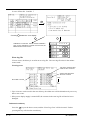
Each external terminal is provided on the rear panel of the analyzer. (See Fig. 3-3)
Wire each terminal, referring to Fig. 3-3 and (1) to (7).
Terminal block 4
Terminal block 5
Terminal block 3
Terminal block 2
Terminal block 1
Connector for
communication
Fig. 3-3 Rear panel
(1)
Power inlet
When using supplied power cable, connect the female side to the power inlet at the rear panel of
the analyzer, and insert the male side into a receptacle matching the rating.
Power inlet (3 pins)
Female
side
(
Supplied power cable
)
Male side
Fig. 3-4
3-6
100 to 240V AC
50/60Hz
IM 11G02M01-01E
When noise source is in the vicinity
Do not install the instrument near an electric device
that generates noise from the power supply (such as
high-frequency furnace and electric welder). If
there is no other choice but to install it near such
devices, provide completely separate power line to
eliminate noise.
In case noise may enter from a relay, solenoid valve,
etc. through power supply, connect a varistor or
spark killer to the noise source as shown below. If
the varistor or spark killer is located away from the
noise source, no effect is obtainable. So, locate near
the noise source.
(2) Analog output signal (AO): terminal block 1,
Output signal:
IR200 power supply
Varistor or
spark killer
Locate and connect
in close proximity
Noise source
1
to
10 , 15
to
20 .
4 to 20 mA DC or 0 to 1 V DC (selected when ordering)
Non-insulated output
Allowable load: 4 to 20 mA DC, 550Ω or less
0 to 1 V DC, 100kΩ or more
•
Analog output is provided from each terminal corresponding to the channel displayed in the
measurement screen.
Note) All of analog output signals for the instrument are not isolated. It is recommended to
isolate signals individually to prevent interference from unnecessary signals or to
prevent external interference, especially leading the cable of more than 30 meters to
outdoor.
(3) O2 sensor input: terminal block 2,
1
–
2
.
Input signal:
External zirconia O2 analyzer:
Zirconia O2 sensor signal (ZX8D*C output)
External O2 analyzer:
0 to 1 V DC (DC input resistor of 1MΩ or more)
•
It is used when the external zirconia O2 analyzer or external O2 analyzer is specified as order.
•
To connect to the output of the external Zirconia analyzer or external O2 analyzer prepared
separately.
•
In case of an external O2 analyzer, input a signal of 0 to 1 V DC with respect to O2 full scale
of the analyzer.
•
In case of built-in O2 analyzer, do not use the terminals.
Note) O2 senser input is not isolated. It is recommended to isolate input signal to prevent
inter ference from unnecessary signals or to prevent external interference.
Zirconia O2 sensor should be installed at a location that is as close to this instrument
as possible.
IM 11G02M01-01E
3-7
(4) Contact input (DI): terminal block 2,
13
to
20 ,
terminal block 3,
5
to
10 .
•
It is for a contact input at no voltage. An input is provided when switching to short circuit
(on) or open (off).
•
No voltage is applied to the terminals.
(5) Contact output (DO): terminal block 3,
13
to
20 ,
terminal block 4 and terminal block 5
•
Contact rating: 250 V AC/2 A, load resistance
•
An output is for a relay contact output. An output is provided when switching to conductive
(on) or open (off).
Note) The wires of analog output signals, O2 senser input and contact input should be fixed
separately from power supply wiring and contact output wiring.
(6) Communication interface: connector for communication (RS-232C interface)
•
3-8
Please refer to the manual (IM 11G02P01-01E) about communication function.
IM 11G02M01-01E
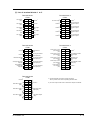
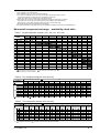
(7) List of terminal blocks 1 to 5
Terminal block 1
<TN1>
CH5 output 2
(AO) 1
1
11
2
12
CH4 output 2
(AO) 1
3
13
4
14
CH3 output 2
(AO) 1
5
15
6
16
CH2 output 2
(AO 1
7
17
8
18
CH1 output 2
(AO) 1
9
19
10
20
Terminal block 2
<TN2>
Unused
Unused
*1
*1
2 CH8 output
1 (AO)
*2
2
O2 sensor input 1
*1
Unused
*1
Unused
*1
2 CH7 output
1 (AO)
Unused
2 CH6 output
1 (AO)
Unused
*1
1
11
2
12
3
13
4
14
5
15
6
16
7
17
8
18
9
19
10
20
Unused
CH4 remote range
changeover input
(DI)
CH3 remote range
changeover input
(DI)
CH2 remote range
changeover input
(DI)
CH1 remote range
changeover input
(DI)
(M3.5 screw)
(M3.5 screw)
Terminal block 3
<TN3>
Terminal block 4
<TN4>
*1
1
11
2
12
3
13
4
14
Remote hold input
(DI)
5
15
6
16
Average value reset
input (DI)
7
17
8
18
Auto calibration
remote start
input (DI)
9
19
10
20
Unused
*1
Unused
Instrument error
(DO)
Contact output for CH4
span calibration
(DO)
1
11
2
12
CH4 range identification
signal output (DO)
Contact output for CH3
span calibration
(DO)
3
13
4
14
CH3 range identification
signal output (DO)
Contact output for CH2
span calibration
(DO)
5
15
6
16
CH2 range identification
signal output (DO)
Contact output for CH1
span calibration
(DO)
7
17
8
18
CH1 range identification
signal output (DO)
Contact output for
zero calibration
(DO)
9
19
10
20
(M3.5 screw)
CH3 alarm output
(DO)
CH2 alarm output
(DO)
CH1 alarm output
(DO)
11
2
12
3
13
4
14
5
15
6
16
7
17
8
18
9
19
10
20
Auto calibration status
contact output
(DO)
Calibration error
contact output
(DO)
Pump ON/OFF contact
output (DO)
Unused
*1
*1) Unused terminals are used for internal connection.
*1
1
*1
Unused
(M3.5 screw)
Terminal block 5
<TN5>
Unused
*1
So they should not be used as repeating terminals either.
*1
*2) O2 sensor input is used when an external O2 analyzer is selected.
Unused
Peak count alarm
output (DO)
CH4 alarm output
(DO)
(M3.5 screw)
IM 11G02M01-01E
3-9
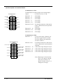
(8) Description on terminal block
Terminal block 1 <TN1>
Terminal block for analog output (non-isolated output)
Terminal block 1
<TN1>
CH5 output 2
(AO) 1
1
2
12
CH4 output 2
(AO) 1
3
13
4
14
CH3 output 2
(AO) 1
5
15
6
16
CH2 output 2
(AO 1
7
17
8
18
9
19
10
20
CH1 output 2
(AO) 1
11
Unused
Unused
Output
: 4 to 20 mA or 0 to 1 V DC
Between 1 – 2
: CH5 output
Between 3 – 4
: CH4 output
Between 5 – 6
: CH3 output
Between 7 – 8
: CH2 output
2 CH8 output
1 (AO)
Between 9 – 10
: CH1 output
2 CH7 output
1 (AO)
Between 11 to 14 : For internal connection. Must not be
wired. (Must not be used as junction
terminal.)
2 CH6 output
1 (AO)
(M3.5 screw)
Between 15 – 16 : CH8 output
Between 17– 18
: CH7 output
Between 19– 20
: CH6 output
Terminal block 2 <TN2>
Terminal block 2
<TN2>
2
O2 sensor input 1
Unused
Unused
Unused
Unused
1
11
2
12
3
13
4
14
5
15
6
16
7
17
8
18
9
19
10
20
(M3.5 screw)
3 - 10
Between 1– 2
: For O2 sensor input. (Input for our
Zirconia oxygen sensor or exernal
O2 sensor. Must not be used unless
O2 meter is added.)
Between 3 to12
: For internal connection. Must not be
wired. (Must not be used as junction
terminal.)
Unused
CH4 remote range
changeover input
(DI)
CH3 remote range
changeover input
(DI)
CH2 remote range
changeover input
(DI)
CH1 remote range
changeover input
(DI)
Between 13 – 14 : CH4 remote range changeover input
Between 15 – 16 : CH3 remote range changeover input
Between 17– 18
: CH2 remote range changeover input
Between 19– 20
: CH1 remote range changeover input
Note) High range is selected when
open. Low range is selected
when short-circuited. For
details of action, refer to “6.1
Changeover of range”.
IM 11G02M01-01E
Terminal block 3 <TN3>
Terminal block 3
<TN3>
1
11
2
12
3
13
4
14
Remote hold input
(DI)
5
15
6
16
Average value reset
input (DI)
7
17
8
18
9
19
10
20
Unused
Unused
Auto calibration
remote start
input (DI)
(M3.5 screw)
Between 1 to 4 : For internal connection. Must
not be wired. (Must not be used
as junction terminal.)
Between 5 – 6
: Remote hold input. No hold
when open. Output hold when
short-circuited.
Between 7 – 8
: Average value reset input.
Short-circuiting the contact input
(for at 1.5 sec or more) resets O2
average and O2 correction
average simultaneously.
Opening it restarts the average
value.
Instrument error
(DO)
CH4 range identification
signal output (DO)
CH3 range identification
signal output (DO)
CH2 range identification
signal output (DO)
CH1 range identification
signal output (DO)
Between 9 – 10 : Automatic calibration remote
start input. Open input after
strapping for at least 1.5 seconds
starts the automatic calibration
whether automatic calibration
setting is ON or OFF.
Between 11 – 12 : Conductive when analyzer unit
error is producted. Normally
open.
Between 13 – 14 : CH4 range identification signal
Between 15 – 16 : CH3 range identification signal
Between 17– 18 : CH2 range identification signal
Between 19– 20 : CH1 range identification signal
Note) Range identification
signal is conductive at
Low range or open at
High range.
In case of 1-range
system, the signal
remains open.
IM 11G02M01-01E
3 - 11
Terminal block 4 <TN4>
Terminal block 4
<TN4>
Contact output for CH4
span calibration
(DO)
1
2
12
Contact output for CH3
span calibration
(DO)
3
13
4
14
Contact output for CH2
span calibration
(DO)
5
15
6
16
Contact output for CH1
span calibration
(DO)
7
17
8
18
Contact output for
zero calibration
(DO)
9
19
10
20
11
(M3.5 screw)
Unused
Auto calibration status
contact output
(DO)
Calibration error
contact output
(DO)
Pump ON/OFF contact
output (DO)
Unused
Between 1 – 2
: CH4 span calibration contact
output
Between 3 – 4
: CH3 span calibration contact
output
Between 5 – 6
: CH2 span calibration contact
output
Between 7 – 8
: CH1 span calibration contact
output
Between 9 – 10 : Zero calibration contact output
When the calibration contact
output is measured with manual
calibration, the calibration
contact corresponding to calibration channel is conductive.
For the automatic calibration,
they are worked sequentially
according to “6.4 Auto calibration setting”. If calibration is
not performed, all of them are
open.
Between 11– 12 : For internal connection. Must
not be wired. (Must not be used
as junction terminal.)
Between 13– 14 : Automatic calibration in
progress, contact output. Conductive during automatic
calibration. Open otherwise.
Between 15– 16 : Calibration error contact output.
Conductive when error is
produced at zero or span calibration. Normally open.
Between 17– 18 : Pump ON/OFF contact output.
(Used for turning ON/OFF the
pump. Conductive during
measurement and open at zero
span calibration.)
Note: For the output of calibration contacts, see
Item 3.5 (9) “Timing of calibration
contact output”.
3 - 12
IM 11G02M01-01E
Terminal block 5 <TN5>
CH3 alarm output
(DO)
CH2 alarm output
(DO)
CH1 alarm output
(DO)
1
11
2
12
3
13
4
14
5
15
6
16
7
17
8
18
: For internal connection. Must not
be wired. (Must not be used as
junction terminal.)
Between 2– 3
: CH3 alarm output. Conductive at 2–
3 and open at 3– 4 when set value is
exceeded. Open at 2– 3 and conductive at 3– 4 otherwise.
and 3– 4
Terminal block 5
<TN5>
Unused
1 and 11 – 14
Between 5– 6
Unused
9
19
10
20
(M3.5 screw)
and 6– 7
Peak count alarm
output (DO)
Between 8– 9
and 9– 10
CH4 alarm output
(DO)
: CH2 alarm output. Conductive at 5–
6 and open at 6– 7 when set value is
exceeded. Open at 5– 6 and conductive at 6– 7 otherwise.
: CH1 alarm output. Conductive at 8–
9 and open at 9– 10 when set value
is exceeded. Open at 8– 9 and
conductive at 9– 10 otherwise.
Between 15–16 : Peak count alarm contact output.
Conductive at 15 – 16 and open at
and 16– 17
16 – 17 when preset peak count is
exceed. Otherwise, open at 15 – 16
and conductive at 16 – 17. For
setting and action, refer to instruction manual “6.6 Peak Alarm
Setting”.
Between 18–19 : CH4 alarm output. Conductive at
18– 19 and open at 19– 20 when set
and 19– 20
value is exceeded. Open at 18– 19
and conductive at 19– 20 otherwise.
IM 11G02M01-01E
3 - 13
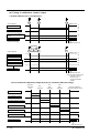
(9) Timing of calibration contact output
1. Manual calibration (See “6.9 Calibration”).
ZERO
ENT
ENT
• Zero calibration
Calibration end
Pump ON/OFF contact
on
off
on
Zero calibration contact
off
CH1 to CH4 span calibration
contact
off
Output hold function
Output signal hold
(with hold ON setting)
Hold extension time
When selecting
CH2 using
and
keys.
ENT
SPAN
ENT
• Span calibration
Calibration end
Pump ON/OFF contact
on
off
Zero calibration contact
off
off
Span 1 calibration contact
on
Span 2 calibration contact
off
Output hold function
Output signal hold
(with hold ON setting)
Hold extension time
Note) The hold extension time
depends on the gas
flow time of the
automatic calibration
settings.
2. In case of automatic calibration (example shown in 6.4.1, Automatic calibration settings)
Automatic
calibration
start
CH1
span
calibration
Zero
calibration
CH2
span
calibration
CH3 span calibration
(automatic calibration end)
Pump ON/OFF contact
Zero calibration contact
CH1 span calibration contact
Zero gas
350s
CH1 span gas
350s
CH2 span calibration contact
CH2 span gas
350s
CH3 span gas
CH3 span calibration contact
350s
Automatic calibration contact
Output hold function
(With hold ON setting)
Output signal hold
Hold extension time
3 - 14
IM 11G02M01-01E
4. OPERATION
4.1 Preparation for operation
(1) Check of gas sampling tube, exhaust tube and wiring
Check that the pipes are correctly connected to the gas sampling port and drain port. Check that
the analyzer is correctly wired as specified.
4.2 Warm-up operation and regular operation
(1) Operation procedure
1. Turn ON the power switch at the left of the front panel.
In one or two seconds, the measurement screen will appear at the front panel.
2. About 2 hour warm-up operation
About 2 hours are needed until the operating performance is stabilized. Warm-up operation
should be continued with the power ON.
3. Setting of various set values
Set required set values according to Chapter 6, “Setting and calibration”.
4. Zero and span calibration
Perform zero calibration and span calibration after warm-up operation.
See Chapter 6.9, “Calibration”.
5. Make moisture interference compensation adjustment (NO Analyzer and SO2 Analyzer).
(See “6.8 Maintenance mode” and “7.4 Moisture interference compensation adjustment” for
details.)
Be sure to perform individual moisture interference compensation adjustment according to
the system in the case of NO Analyzer and SO2 Analyzer. Otherwise measurement is
affected by moisture interference.
6. Introduction and measurement of measured gas
Start measurement by introducing measured gas into the analyzer.
Note) While in warm-up operation, the concentration reading may be beyond the
upper limit of the range (range-over)
or below the lower limit
(range-under)
.
But this is not an error.
IM 11G02M01-01E
4-1
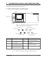
5.
DESCRIPTION OF DISPLAY AND OPERATION PANEL
This section describes the display and operation panel of the gas analyzer. It also explains the name and
description of function on the operation panel. See Fig. 5-1.
5.1 Name and description of operation panel
Display
INFRARED GAS ANALYZER
POWER
Power switch
MODE
ZERO
ESC
ENT
SPAN
Controls
• Display : The measurement screen and the setting items are displayed.
• Controls : The configuration is as shown below.
(5)ESCAPE key
(3)UP key
(1)MODE key
(7)ZERO key
MODE
ESC
ZERO
ENT
(8)SPAN key
(2)SIDE key
(4)DOWN key
Name
Description
(1) MODE key Used to switch the mode.
(2) SIDE key
Used to change the selected
item (by moving the cursor)
and numeral digit.
SPAN
(6)ENTRY key
Name
(5) ESCAPE
key
(6) ENTRY
key
Description
Used to return to a previous screen
or cancel the setting midway.
Used for confirmation of selected
items or values, and for execution
of calibration.
(3) UP key
Used to change the selected
(7) ZERO key Used for zero calibration.
item (by moving the cursor)
and to increase numeral value.
(8) SPAN key Used for span calibration.
(4) DOWN key Used to change the selected
item (by moving the cursor)
and to decrease numeral value.
Fig. 5-1 Name and description of operation display and panel
IM 11G02M01-01E
5-1
5.2 Overview of display and operation panel
• Measurement mode
*1
*1) The screen configuration depends upon the display channel.
When channel 5 or later is displayed on the screen, scroll the
screen by using the UP
or DOWN
key.
ZERO
ZERO Calibration
• Measurement mode
SPAN Calibration
SPAN
MODE
ESC
• User mode
ESC
ESC
• User mode
1. Changeover of Range
2. Setting about Calibration
3. Alarm Setting
4. Setting of Auto Calibration
5. Setting of Auto zero
calibration
6. Setting of Peak Alarm
7. Parameter Setting
*2) Peak alarm is displayed
only when specified as an
option.
• Changeover of
Range
• Setting about
Calibration
ESC
• Alarm Setting
ESC
• Selection of items
Calibration value
Calibration gas
About Zero calibration
About Calibration range
Auto calibration component
*3) "Calibration gas" is displayed if NO or SO2 is
included in components to be analyzed.
• Selection of items
Start time
Cycle
Flow time
Auto calibration ON/OFF
Auto zero calibration stop
• Setting of Auto
Calibration
ESC
• Setting of Auto
zero calibration
ESC
• Setting of
Peak Alarm
ESC
• Parameter
Setting
• Selection of items
Start time
Cycle
Flow time
ON/OFF
Auto zero calibration stop
• Selection of items
Peak alarm ON/OFF
Peak alarm value
Peak alarm count
Hysteresis
• Selection of items
Current time
Key lock
Remote range
Output hold
Reset Average
output
Response time
Average period
To maintenance
mode
: Current time setting
: Key lock ON/OFF
: Remote range ON/OFF
: ON/OFF
: Average value resetting
: Response time (filter)
: Average time setting
: Maintenance mode
(entry of password)
Fig. 5-2
5-2
IM 11G02M01-01E
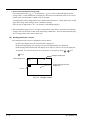
5.3 Overview of display screen
(1) Measurement mode screen
On turning on the power switch, the Measurement Mode screen will appear.
The measurement screen depends on the number of components. The following screen configuration shown as an example is for CO2, CO, O2 (Output at channel 6).
When channel 5 or later is displayed, scroll
or
key to view another configuration which is
beyond the screen.
1
2
3
No,
Name
4
5
No,
Function
6
Name
8
7
Description
1
Component
display
Displays component of instantaneous value, converted instantaneous value, converted average
value, etc.
5
Peak alarm
component
display
2
Concentration
display
Displays measured value of
concentration.
6
Peak alarm
Displays peak alarm concentraconcentration tion (Upper limit value).
display
3
Range display
Displays range values.
7
Peak alarm
count
Displays the alarm times exceeding the peak value.
4
Unit display
Displays unit with ppm and
vol%.
8
Peak alarm
unit display
Displays unit of peak alarm with
times/h.
Displays peak alarm component.
Fig. 5-3 Name and function of measurement mode screen
• Instantaneous value and concentration value:
The concentration display of CH (component) where sampling components such as “CO2”,
“CO” or “O2 are displayed in the component display, indicates current concentration values of
the measured components contained in gas that is now under measurement.
• O2 correction concentration value:
CH (components) where “cv**” is displayed as “cv CO” in the component display are calculated
from the following equation, by setting sampling components, O2 instantaneous/concentration
values and O2 correction reference value (see item 6.8).
Conversion output=
21 - On
21 - Os
K
× Cs
On:
The value of the O2 correction referance value
(Value set by application)
Os:
Oxygen concentration (%)
Cs:
Concentration of relevant measured component
K:
The value of the fractional part is this equation.
where, K is When K 4, K=4.
When K < 0, K=4.
When Cs < 0, K=0.
The correction components are CO and SO2 only.
IM 11G02M01-01E
5-3
• O2 correction concentration average value:
AV
CH (component) where “ CV ** ” is displayed as “ AV
CV CO” in the component display and O2
average value, a value obtained by averaging O2 conversion concentration value or O2 concentration value in a fixed time is output every 30 seconds.
Averaging time can be changed between 1 minute and 59 minutes or 1 hour and 4 hours according to the average time settings (See 6.7 Parameter setting).
(The set time is displayed as “1h” , for instance, in the Range display.)
* The measurement ranges of O2 correction concentration value and O2 correction concentration
average value are the same as that of the measuring components. Also, the measurement range
of O2 average value is the same as that of O2.
(2) Setting/selection screen
The setting/selection screen is configured as shown below:
• In the status display area, the current status is displayed.
• In the message display area, messages associated with operation are displayed.
• In the setting item and selection item display area, items or values to be set are displayed,
as required. To work on the area, move the cursor to any item by using
,
and
keys.
Message display area
Status display area
Setting item/selection item
display area
Cursor
Fig. 5-4 Display screen
5-4
IM 11G02M01-01E
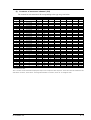
(3) Contents of measured channel (CH)
The contents in each measured CH corresponding to the type are given below:
Suffix/Option Code
Measurable
O2
O2 correction
component analyzer
Output and Corresponding Channel
CH1
CH2
-A
-B
-C
-D
-E
-F
-G
-H
-J
-K
-L
-M
-A
-B
-C
-D
-E
-F
-G
-H
-J
-K
-L
-M
-A
-B
-E
-F
-G
-J
-K
N
N
N
N
N
N
N
N
N
N
N
N
1, 2, 3
1, 2, 3
1, 2, 3
1, 2, 3
1, 2, 3
1, 2, 3
1, 2, 3
1, 2, 3
1, 2, 3
1, 2, 3
1, 2, 3
1, 2, 3
1, 2, 3
1, 2, 3
1, 2, 3
1, 2, 3
1, 2, 3
1, 2, 3
1, 2, 3
Not specified
Not specified
Not specified
Not specified
Not specified
Not specified
Not specified
Not specified
Not specified
Not specified
Not specified
Not specified
Not specified
Not specified
Not specified
Not specified
Not specified
Not specified
Not specified
Not specified
Not specified
Not specified
Not specified
Not specified
/K
/K
/K
/K
/K
/K
/K
SO2
CO
CO2
CH4
NO
CO2
CH4
CO2
CO2
NO
NO
NO
SO2
CO
CO2
CH4
NO
CO2
CH4
CO2
CO2
NO
NO
NO
SO2
CO
NOX
CO2
CH4
CO2
NOX
CH3
CO
CO
CH4
CO
SO2
CO
SO2
O2
O2
O2
O2
O2
CO
CO
CH4
CO
SO2
CO
SO2
O2
O2
O2
CO
CO
CO
SO2
O2
O2
O2
CH4
O2
O2
CO
Correct SO2
Correct CO
Correct NOX
O2
O2
CH4
O2
-L
1, 2, 3
/K
NOX
CO
O2
-M
1, 2, 3
/K
NOX
SO2
CO
CH4
CH5
CH6
CH7
CH8
CH4
CO
O2
O2
Correct SO2 av.
Correct CO av.
Correct NOX av.
Correct CO
Correct CO
O2
Correct NOX
O2 av.
O2 av.
O2 av.
Correct CO av.
O2 av.
Correct CO av.
O2 av.
Correct CO Correct CO av.
O2 av.
Correct SO2 Correct NOX av. Correct SO2 av.
O2 av.
Correct NOX Correct CO Correct NOX av. Correct CO av.
O2 av.
O2
Correct NOX Correct SO2 Correct CO
O2 av.
* How to Read the Table
“SO2” in the CH1 column means that the display and output of CH1 correspond to SO2 component. “Correct XX” means an instantaneous XX
value after O2 correction, “Correct XX av.” an average XX value after O2 correction, and “O2 av.” an average O2 value.
IM 11G02M01-01E
5-5
5.4 General operation
•
Measurement mode
The measurement mode can be
displayed for up to 5 channels in
a single screen. When viewing a
channel beyond the 5 channels,
or
) key and the
press the (
screen can be scrolled one by one
channel at a time.
ZERO
See 6.9.1, Zero
calibration
See 6.9.2, Span
calibration
SPAN
MODE
•
ESC
User mode displays the following settings.
Changeover of range
Calibration setting
Alarm setting
Setting of auto calibration
Setting of auto zero calibration
Peak alarm setting
Parameter setting
For setting settings, refer to “6,
Setting and calibration”.
5-6
IM 11G02M01-01E
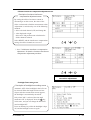
6. SETTING AND CALIBRATION
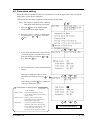
6.1 Changeover of range
This mode is used to select the ranges of measured
components.
1. During measurement, press the
MODE
MODE
key to
display the User mode.
2. Point the cursor to “Changeover of Range”.
Press the ENT key.
ENT
3. The “Channel Selection” screen appears.
“ or “
” key until the “ ”
Press the “
cursor moved selects a desired CH (component).
4. After selection, press the
ENT
key.
Note) The range of O2 correction instantaneous values and O2 correction average values is automatically switched by
changing the range of instantaneous
value of each CH (component).
(
)
ENT
▲
5. In the Range Setting screen that appears,
or
move the cursor by pressing the
key to select the range. (The range with a
mark of is currently selected.)
6. After selection, press the
ENT
key.
7. Measurement is conducted within the selected
range. The range identification signal (CO) is
shorted with the low range (Range 1), and
open with the high range (Range 2).
Note) If the Remote Range is set to ON, the
changeover of range cannot be performed on the screen.
(
)
ENT
End of Range Changeover
To close Changeover of range
To close Changeover of range, or cancel the
commad midway, press the ESC key.
A previous screen will return.
IM 11G02M01-01E
6-1
6.2 Calibration setting
This mode is used to set calibration concentration and actions. The calibration setting involves
calibration concentration, calibration gas, zero calibration, calibration range and auto-calibration
component.
“Calibration Gas” is displayed if NO or SO2 is included in components to be analyzed.
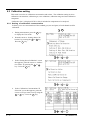
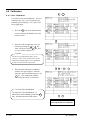
6.2.1 Setting of calibration concentration
It allows you to set concentrations of the standard gas (zero and span) of each channel used for
calibration.
MODE
1. During measurement, press the
to display the User mode.
MODE
key
2. Point the cursor to “Setting about Calibration” by pressing the
or
key.
Press the
ENT
key.
(
)
ENT
(
)
ENT
(
)
ENT
3. In the “Setting about Calibration” screen
that appears, point the cursor to “Calibration Value” by pressing the
or
key. Press the
key.
ENT
4. In the “Calibration Concentration CH
Selection” screen that appears, point the
cursor to CH you want to set by using the
or
key. Press the
key.
ENT
6-2
IM 11G02M01-01E
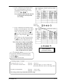
5. In the “Calibration Concentration Selection” screen that appears, select any
concentration item you want to set by
pressing the
,
key.
Note) Analyzers other than the zirconia
O2 instrument cannot perform
zero setting.
Cursor for
setting value
ENT
6. In the “Calibration Concentration Value
Setting” screen that appears, enter calibration gas concentration values (zero and
or
span). For value entry, press the
key, and a 1-digit value increases or
decreases. By pressing the
, the digit
moves.
After setting, save the entry by pressing
the
key. The saved value becomes
valid from the next calibration process.
ENT
Note) Enter the set values corresponding
to each range. When the O2 measurement uses atmospheric air for
the zero gas, set the concentration
value to 21.00. When the cylinder
air is used, set to the concentration
value as indicated on the cylinder.
ENT
End of Calibration
Concentration Setting
To close the setting
To close the calibration concentration value
setting process or cancel this mode midway,
press the ESC key.
A previous screen will return.
Setting range of values
Paramagnetic O2, CO2, CO,
SO2, CH4 and NO measurement
Zirconia O2 measurement
:
Zero gas : Fixed at 0
Span gas : Minimum digit, 1 to 105% of full scale
(Full scale (FS) is the same as each range value.)
Zero gas : 5 to 25 vol%
Span gas : 0.01 to 5 vol%
The setting cannot be performed beyond the range.
IM 11G02M01-01E
:
6-3
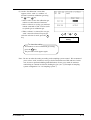
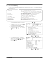
6.2.2 Setting of calibration gas
Whether moisture is contained in zero gas and span gas used for calibration can be set in advance
as follows. Make the setting according to the sampling system created.
If sampling system controls the moisture content in the calibration gas (ZERO or SPAN) to
become the same as that in the sample gas to be fed to the analyzer using an electronic cooler,
etc., set “With” water vapor.
MODE
(1) Press the MODE key in measurement state to
display the User mode.
(2) Move the cursor to Setting about
or the
Calibration using the
ENT
key.
and then press the
key,
(
)
ENT
(
)
ENT
(
)
ENT
(3) On the Setting about Calibration screen
that appears, move the cursor to “Calibraor the
tion Gas” using the
and then press the ENT key.
key,
(4) On the “Gas Selection” screen that
appears, move the cursor to the gas to be
or the
key,
selected using the
and then press the ENT key.
6-4
IM 11G02M01-01E
(5) On the “Gas Selection” screen that
appears, select “with” or “without” of
moisture content in calibration gas using
or the
key.
the
• Select “with” to have the calibration gas
contain a certain amount of moisture.
• Select “without” to use dry gas (moisture
content: saturated at 70°C or lower) such
as cylinder gas as calibration gas.
• When “without” is selected for zero gas,
“with” cannot be selected for span gas.
After the selection is made, press the
key.
(
)
ENT
ENT
End of Calibration gas
Setting
To close the setting
To terminate or cancel calibration gas setting,
press the ESC key.
The previous screen appears again.
Note: Be sure to make the setting according to the sampling system created. We recommend
you to select “with” moisture in zero gas for the measurement of NO and SO2. In this
case, be sure to perform bubbling (humidification) of zero gas to make its moisture
content kept at constant level before feeding the gas. (See “(7) Example of sampling
system configuration” in “3.4 Sampling system.”)
IM 11G02M01-01E
6-5
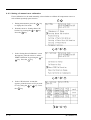
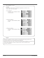
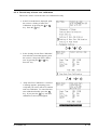
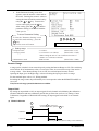
6.2.3 Setting of manual zero calibration
If zero calibration is to be made manually, select whether to calibrate all components at once or
each of them separately upon selection.
MODE
1. During measurement, press the
to display the User mode.
MODE
key
2. Point the cursor to “Setting about Calibration” by pressing the
or
key.
key.
Press the
ENT
(
)
ENT
(
)
ENT
(
)
3. In the “Setting about Calibration” screen
that appears, point the cursor to “About
or
ZERO Calibration” by pressing the
key. Press the
key.
ENT
4. In the “CH Selection” screen that
appears, point the cursor to CH you want
or
key. Press
to set by using the
the ENT key.
6-6
ENT
IM 11G02M01-01E
5. In the “Zero Calibration Selection”
screen that appears, select “at once” or
or
key.
“each” by pressing the
When selecting “at once”, the CH (components) to be set can be zero-calibrated
at the same time. When selecting “each”,
either of the CH (components) to be
selected is zero-calibrated. After setting,
press the
key, and the calibration you
specified is carried out.
ENT
To close “About ZERO Calibration”
To close “About ZERO Calibration” setting or to
cancel this mode midway, press the ESC key.
A previous screen will return.
(
)
ENT
End of Manual Zero Calibration Setting
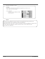
Example
Whether upon selection “each” or “at once” can be determined for each CH (component).
•Setting “each”
Select the CH (component) and then perform zero calibration on the manual
zero calibration screen.
•Setting “at once”
At a manual zero calibration, CHs (components) for which “at once” was selected can
simultaneously be calibrated.
* When the zirconia O2 analyzer uses the cylinder air or atmospheric air for the zero gas,
select “at once”.
Manual Calibration screen
When “each” is set for each CH
When “at once” is set for CH1 and CH2
(CH3 is set “each”)
A single cursor will appear.
Cursors will appear on all components
where "at once" is set.
IM 11G02M01-01E
6-7
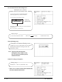
6.2.4 Setting of calibration range
This mode is used to set if the range of each CH (component) at the zero and span calibration
(manual calibration or auto calibration) should be calibrated with a single range or 2 ranges.
MODE
1. During measurement, press the
to display the User mode.
MODE
key
2. Point the cursor to “Setting about Calior
key.
bration” by pressing the
Press the
key.
ENT
(
)
ENT
(
)
ENT
3. In the “Setting about Calibration” screen
that appears, point the cursor to “About
Calibration Range” by pressing the
or
key. Press the
key.
ENT
4. In the “Calibration Range CH Selection”
screen that appears, point the cursor to
the CH you want to set by pressing the
or
key. Press the
key.
ENT
(
6-8
)
ENT
IM 11G02M01-01E
5. In the “Calibration Range Selection” screen
that appears, select “both” or “current” by
or
key.
pressing the
• When selecting “both”, Range 1 and Range
2 of the set CH are calibrated together.
• When selecting “current”, the range alone
displayed at the set CH is calibrated.
To close Setting of Calibration Range
To close Setting of Calibration Range or
ESC key.
to cancel this mode midway, press the ESC
A previous screen will return.
(
)
ENT
End of Calibtation Range Setting
Example
CH1
CO2
Range 1: 0 to 10 vol%
Range 2: 0 to 20 vol%
both
CH2
CO
Range 1: 0 to 500 ppm
Range 2: 0 to 2000 ppm
current
CH1: Range 1 and Range 2 are calibrated together, with zero or span calibration.
CH2: Only currently displayed range is calibrated, with zero or span calibration.
Manual Calibration screen
In case of both setting
Two cursors will appear in both ranges
Note) When calibration is performed by the “both” setting under the normal operating
condition, prepare a span gas cylinder on the normal operating range side. It is
recommend to perform span gas calibration in the normal operating range.
The other range that is calibrated by “both” may result in some error (max. of ±5% of
FS).
IM 11G02M01-01E
6-9
6.2.5 Setting of auto-calibration component
It sets the CH (component) to be calibrated in the auto-calibration.
MODE
1. During measurement, press the
to display the User mode.
MODE
key
2. Point the cursor to “Setting about Calior
key.
bration” by pressing the
key.
Press the
ENT
(
)
ENT
(
)
ENT
3. In the “Setting about Calibration” screen
that appears, point the cursor to “Auto
Calibration Components” by pressing the
or
key. Press the
key.
ENT
4. In the “Auto Calibration Components”
selection screen that appears, point the
cursor to the CH you want to set by
or
key. Press the
pressing the
key.
ENT
(
6 - 10
)
ENT
IM 11G02M01-01E
5. In the “Auto Calibration component
Selection” screen that appears, select
“enable” or “disable” by pressing the
or
key. After setting, press the
key.
ENT
To close Auto Calibration
Component setting
To close “Setting of Auto Calibration
Component” or to cancel this mode midway,
press the ESC
ESC key.
A previous screen will return.
(
)
ENT
End of Auto Calibtation Component Setting
Example
Auto calibration is made in the following rules according to the setting.
1. Zero calibration at once of CHs (components) which were set to enable .
2. The span of CHs (components) which were set to enable is calibrated in the ascending
order of CH number.
Example 1. In case all of CH1: CO2, CH2: CO, CH3: O2, were set to enable .
Zero calibration (at once) of CH1 to CH3
span calibration of CH1 (CO2)
span calibration of CH2 (CO)
span calibration of CH3 (O2)
Example 2. In case, out of CH1: CO2, CH2: CO and CH3: O2, CH1 ( CO2) was set to enable ,
CH2 (CO) was set to enable an CH3 (O2) was set to disable .
Zero calibration (at once) of CH1 and 2
span calibration of CH1 (CO2)
span calibration of CH2 (CO)
Caution
The components which were set to enable is calibrated to zero at once at the time of
auto calibration regardless of setting in 6.2.3 Setting of manual zero calibration .
IM 11G02M01-01E
6 - 11
6.3 Alarm setting
6.3.1 Setting of alarm values
This mode is used to set the upper and lower limit value to provide an alarm output against
measured concentration during measurement. Before changing the alarm setting, set the ON/OFF
to OFF.
MODE
1. During measurement, press the
to display the User mode.
MODE
key
2. Point the cursor to “Alarm Setting” by
pressing the
or
key. Press the
key.
ENT
(
)
ENT
3. After the alarm setting, CH selection
screen has appeared, operate the
or
key until the cursor is aligned with a
desired CH and press the
key.
ENT
(
)
ENT
4. After the alarm item selection screen has
or
key until
appeared, operate the
the cursor is aligned with a desired item
and press the
key.
ENT
Caution
Set the values so that upper limit value > lower
limit value and that (upper limit value - lower
limit value) > hysteresis error.
The alarm is activated in each range
independently from the settings of each range.
(
6 - 12
)
ENT
IM 11G02M01-01E
After setting, the alarm setting is now
key.
completed by pressing the
Cursor for setting value
ENT
To close the Alarm Setting
To close the " Alarm Setting" or to cancel
ESC key.
this mode midway, press the ESC
A previous screen will return.
Setting Range
0 to 100%FS (Settable in each range)
ENT
End of Alarm Setting
Description of setting items
Upper limit value: Sets the upper limit value (concentration) of alarm.
Lower limit value: Sets the lower limit value (concentration) of alarm.
Contact action:
Selects one of upper limit alarm, lower limit alarm, and upper limit
or lower limit alarm.
Upper limit alarm ... Alarm contact operates when above upper limit value.
Lower limit alarm ... Alarm contact operates when below lower limit value.
Upper limit alarm or lower limit alarm ...Alarm contact operates when
above upper limit value or below
lower limit value.
ON/OFF: Enables the alarm function if set at "ON", or disables the alarm function if set at "OFF".
* The upper limit value cannot be set below the lower limit value, and the lower limit value
cannot be set above the upper limit value.
If it is desired to set the upper limit value below the lower limit value already stored in the
memory, reduce the lower limit value beforehand, or vice versa.
Typical on-screen display when an alarm occurs
When an upper limit alarm has
occurred, the “High alarm” message
lights at CH (component)
(“Low alarm” at lower limit alarm).
CH
NOalarm
X
High
0-100
CH
SO2
0-100
CH
CO2
CH
CO
0-10
0-100
CH
O2
0-25
---ppm
0.0
0. 0 0 3
0.0
2 1.0 0
ppm
vol%
ppm
vol%
Caution
• For 10 minutes after turning on power, the alarm judgment is inactive.
IM 11G02M01-01E
6 - 13
6.3.2 Hysteresis setting
To prevent chattering of an alarm output near
the alarm setting values, set hysteresis.
1. In the “Alarm Setting CH Selection”
screen that appears, point the cursor to
or
“Hysteresis” by pressing the
key. Press the
key.
ENT
(
)
ENT
2. In the “Hysteresis Value Setting” screen
that appears, enter hysteresis values.
For the value entry, 1-digit value is
increased or decreased by pressing the
or
key, and pressing the
key
moves the digit. After setting, press the
key to carry out hysteresis.
ENT
To close Hysteresis Setting
To close the "Hysteresis Setting" or cancel
the mode midway, press the ESC key.
A previous screen will return.
ENT
End of Hysteresis Setting
Setting range
0 to 20% of full scale
A full scale means each range provides a full
scale of width.
Caution
The hysteresis is common to all CHs
(components).
Hysteresis (In case of upper limit alarm)
If hysteresis values exceed the upper limit value as shown in graph, an alarm output is
provided. Once the alarm output is turned “ON”, it remains “ON” until the value falls
below the set lower limit of the hysteresis indication.
Upper limit value
Hysteresis width
ON (conductive)
Alarm
6 - 14
OFF (open)
IM 11G02M01-01E
6.4 Setting of auto calibration
6.4.1 Auto calibration
Auto calibration is automatically carried out
when zero calibration and span calibration are
set.
MODE
Before changing the setting of auto calibration,
set the ON/OFF to “OFF”.
1. During measurement, press the
to display the User mode.
MODE
key
2. Point the cursor to “Setting of Auto
or
Calibration” by pressing the
key. Press the
key.
ENT
3. In the “Setting of Auto Calibration”
screen that appears, point the cursor to
any item you want by pressing the
or
key. Press the
key.
(
)
ENT
ENT
4. In the “Auto Calibration Parameter
Setting” screen that appears, perform the
value entry or the setting. For the value
entry or setting change, use the
or
key. To change the setting, use the
key to move the cursor to the right.
key, and auto
After setting, press the
calibration is carried out by the entered
setting value.
(
)
ENT
ENT
Description of setting items
• Start Time
: Setting at the first calibration
(day of the week, hour, minute)
• Cycle
: A period between the start time of one
calibration and another
(unit : hour/day)
• Flow Time : The time required for the calibration gas
to be replaced in the cell
• ON/OFF
: Auto zero calibration ON or OFF
ENT
To close Setting of Auto calibration
End of Auto Calibration Setting
To close the "Setting of Auto calibration" or cancel
ESC key.
this mode midway, press the ESC
A previous screen will return.
IM 11G02M01-01E
6 - 15
The auto calibration status contact output is closed while auto calibration is in progress (hold extension
time by the length of time the same as gas replacement time included if the hold setting is set to “ON”),
and open in other cases.
Example
Start Time
Cycle
Flow Time
ON/OFF
SUN
1
350
12:00
day
sec
ON
In case where auto calibration is carried out at the above setting.
Sunday
12:00
Cycle
Monday
12:00
Tuesday
12:00
: Under Auto calibration
CH1
CH2
CH3
Zero
Span
Span
Span
calibration
calibration calibration calibration
350sec.
350sec.
350sec.
Flow Time
(An example of “CH1: through CH3: enable”, as given in Item 6.2.5 “Auto Calibration
Components”.)
Setting range
Cycle
Flow Time
: 1 to 99 hours or 1 to 40 days (initial value 7days)
: 60 to 599 sec
(initial value 300sec)
Caution
• When an auto calibration starts, the measurement screen automatically appears.
• Any key operation other than key lock ON/OFF and forced stop of auto calibration
(see Item 6.4.2) is not permitted during auto calibration. Auto Calibration Cancel
cannot be performed with the key lock to ON . To cancel auto calibration forcedly,
set the key lock to OFF and then execute Auto Calibration Cancel .
• Turn on the power again after it is turned off (including the case of power failure) at
the time set as the next start time in auto calibration, and then repeat it in the set
cycle.
Remote start
Whether the auto calibration is set at ON or OFF, an auto calibration is available by keeping the
remote start input short-circuited for at least 1.5 seconds.
Short-circuit (keep at least 1.5 sec.)
Remote start input
6 - 16
Open
IM 11G02M01-01E
6.4.2 Forced stop of auto calibration
This mode is used to cancel the auto calibration forcedly.
1. In the User mode that is displayed, point
the cursor to “Setting of Auto Calibraor
key.
tion” by pressing the
Press the
key.
ENT
(
)
ENT
2. In the “Setting of Auto Calibration” item
selection screen that appears, point the
cursor to “Stop Auto Calibration” by
pressing the
or
key. Press the
key.
ENT
(
)
ENT
3. “Stop Auto Calibration” is inverted. A
message appears, prompting you to
verify that you want to cancel or continue
auto calibration. To cancel the auto
calibration forcibly, press the
key. If
key, auto calibration is
you press the
cancel (not stopped).
ENT
ESC
IM 11G02M01-01E
6 - 17
“Auto Calibration” screen
Example
In case where setting the auto calibration components (see Item 6.2.5) to
“CH1: enable” and “CH2: enable”.
• Zero calibration
A message, “Zero calibration” blinks
at CH1 and CH2.
• CH1 span calibration
A message, “Span calibration” blinks
at CH1.
• CH2 span calibration
A message, “Span calibration” blinks
at CH2.
Caution
During auto calibration, any key operation is not permitted other than operations such
as key lock ON/OFF and “Forced Stop of Auto Calibration”.
When the key lock is set at “ON”, even the “Forced Stop of Auto Calibration” cannot be used.
To stop “Auto Calibration” forcedly, set the key lock to “OFF” and then execute
“Stop Auto Calibration”.
6 - 18
IM 11G02M01-01E
6.5 Setting of auto zero calibration
6.5.1 Auto zero calibration
Auto zero calibration is automatically carried out
when zero calibration are set.
Components for which a calibration is to be
made are determined by setting of auto calibration component in 6.2.5.
MODE
Before changing the setting of auto zero calibration, set the ON/OFF to “OFF”.
1. During measurement, press the
to display the User mode.
MODE
key
2. Point the cursor to “Setting of Auto Zero
or
Calibration” by pressing the
key. Press the
key.
ENT
3. In the “Setting of Auto Zero Calibration”
screen that appears, point the cursor to
any item you want by pressing the
or
key. Press the
key.
(
)
ENT
ENT
4. In the “Auto Zero Calibration Parameter
Setting” screen that appears, perform the
value entry or the setting. For the value
entry or setting change, use the
or
key. To change the setting, use the
key to move the cursor to the right.
After setting, press the
key, and auto
zero calibration is carried out by the
entered setting value.
ENT
(
)
ENT
Description of setting items
• Start Time
: Setting at the first calibration
(day of the week, hour, minute)
• Cycle
: A period between the start time of one
calibration and another
(unit : hour/day)
• Flow Time : The time required for the calibration gas
to be replaced in the cell
• ON/OFF
: Auto zero calibration ON or OFF
To close "Auto Zero Calibration"
To close the " Auto Zero Calibration " or cancel
this mode midway, press the ESC
ESC key.
A previous screen will return.
IM 11G02M01-01E
ENT
End of Auto Zero Calibration Setting
6 - 19
The auto calibration status contact output is closed while auto zero calibration is in progress (hold
extension time by the length of time the same as gas replacement time included if the hold setting is set to
ON), and open in other cases.
Example
Start Time
SUN
12:00
Cycle
Flow Time
12
300
hour
sec
ON/OFF
ON
In case where auto zero calibration is carried out at the above setting.
Sunday
12:00
Cycle
Zero
calibration
Monday
12:00
Tuesday
12:00
Setting range
: Under Auto zero
calibration
300sec
Flow Time
(An example of “CH1: through CH3: enable”, as given in Item 6.2.5 “Auto Calibration
Components”.)
Setting range
Cycle
Flow Time
•
•
•
•
: 1 to 99 hours or 1 to 40 days (initial value 7days)
: 60 to 599 sec
(initial value 300sec)
Caution
When an auto zero calibration starts, the measurement screen automatically appears.
Any key operation other than key lock ON/OFF and forced stop of auto zero calibration
(see Item 6.5.2) is notpermitted during auto zero calibration. Auto Zero Calibration
Cancel cannot be performed with the key lock to ON. To cancel auto zero calibration
forcedly, set the key lock to OFF and then execute Auto Zero Calibration Cancel .
If the auto calibration period and auto zero calibration period have
overlapped, the auto calibration is retained, ignoring the auto zero calibration
of that period.
Turn on the power again after it is turned off (including the case of power failure) at
the time set as the next start time in auto zero calibration, and then repeat it in the set
cycle.
6 - 20
IM 11G02M01-01E
6.5.2 Forced stop of auto zero calibration
This mode is used to cancel the auto zero calibration forcedly.
1. In the User mode that is displayed, point
the cursor to “Setting of Auto Zero
or
Calibration” by pressing the
key. Press the
key.
ENT
(
)
ENT
2. In the “Setting of Auto Zero Calibration”
item selection screen that appears, point
the cursor to “Stop Auto Zero Calibration” by pressing the
or
key.
Press the key.
(
)
ENT
3. “Stop Auto Zero Calibration” is inverted.
A message appears, prompting you to
verify that you want to cancel or continue
auto zero calibration. To cancel the auto
zero calibration forcibly, press the
key. If you press the
key, auto zero
calibration is cancel (not stopped).
ENT
ESC
IM 11G02M01-01E
6 - 21
“Auto Zero Calibration” screen
Example
In case where setting the auto calibration components (see Item 6.2.5) to
“CH1: enable” and “CH2: enable”.
• Zero calibration
A message, “Zero calibration” blinks
at CH1 and CH2.
Caution
During auto zero calibration, any key operation is not permitted other than operations such
as key lock ON/OFF and “Forced Stop of Auto Zero Calibration”.
When the key lock is set at “ON”, even the “Forced Stop of Auto Zero Calibration” cannot be used.
To stop “Auto Zero Calibration” forcedly, set the key lock to “OFF” and then execute
“Stop Auto Zero Calibration”.
6 - 22
IM 11G02M01-01E
6.6 Peak alarm setting
When the number of peaks of which CO concentration exceeds the upper limit value exceeds the
setting time, a peak alarm is outputted.
This section describes how to perform various settings of peak alarm.
Note) The setting is optional and is valid only
when peak alarm function is provided.
MODE
1. Press the
key in the Measurement
mode, and the User mode appears.
MODE
2. Point the cursor to “Setting of Peak Alarm”
by pressing the
or
key. Press the
key.
ENT
(
)
ENT
(
)
ENT
(
)
ENT
3. In the “Peak Alarm Setting” item selection
screen that appears, point the cursor to any
or
item you want by pressing the
key. Press the
key.
ENT
4. Then, enter numeric values and perform the
setting.
Entering or setting the numeric values
should be carried out by using the
or
key.
key, and the set
After setting, press the
values you entered are saved.
ENT
Description of setting items
• Peak Alarm
: Setting of peak alarm is performed
with ON/OFF.
• Alarm value : If peak concentrations exceed
the set alarm value, a peak counter
counts 1 time.
• Alarm Count : When a peak in excess of the
setting time occurs, a peak count
alarm output is provided.
• Hysteresis
: To prevent possible chattering
when the peak value may exceed
the set peak concentration by only
1 time, the peak count has an
allowance in the hysteresis width.
IM 11G02M01-01E
End of Peak Alarm Setting
6 - 23
Setting range
• Alarm Value
• Alarm Count
• Hysteresis
: 0 to 1000 ppm 5 ppm step
(initial value: 500 ppm)
: 1 to 99 times
(initial value: 5 times)
: 0 to 20% of full scale
(initial value: 0% of full scale)
* The hysteresis setting is made in terms of full scale.
Action of peak alarm
Example
(ON)
(OFF)
If CO concentration exceeds the alarm value, counting will begin. If the number of peaks is over
the set times per hour, a peak count alarm becomes closed (ON). If it is less than the set times per
hour, it is open (OFF). Since 5 times of peaks /hour is marked at (1)
section from the above
graph, the peak count alarm is turned ON. Since peaks of more than 5 times per 1 hour occur at
the interval between (1) and (2)
, the peak count alarm remains ON. Since at (2), peaks are
reduced to 4 times per hour, it is turned OFF.
Like the hysteresis of the alarm setting , the hysteresis prevents possible chattering when
measured gas is fluctuated near the alarm value.
* For 10 minutes after the power is turned ON, a peak alarm counting is not carried out.
Releasing peak alarm
To release the peak alarm, set the peak alarm to OFF.
Turning on the peak alarm initiates counting from 0.
6 - 24
IM 11G02M01-01E
6.7 Parameter setting
It allows you to carry out the parameter setting such as time, key lock, etc., as required. Items to be
set are as follows:
Description of setting items
• Current Time
• Key Lock
• Remote Range
• Output Hold
• Reset Average Output
• Response Time
• Average Period
• Maintenance mode
: Sets the current day of the week, hour and time.
Note: The clock backup time is 2 days. If power is turned on after
it is kept off for 2 days or louger, make the time setting again.
: Sets with ON/OFF so that any key operation except the key
lock OFF cannot be performed.
: Sets with ON/OFF whether the Range Switching is
made valid or invalid by external input.
: Sets whether Calibration Output is held or not.
: Resets the average value.
: Sets the response time of electrical system.
: Sets the moving average time.
: Enters passwords to switch to the Maintenance mode.
* For the maintenace mode, see Item 6.8.
1. To display the User mode, press the
key in the measurement mode.
MODE
MODE
2. Point the cursor to “Parameter Setting”
or
key. Press the
by pressing the
key.
ENT
(
)
ENT
(
)
ENT
3. In the “Parameter Setting” screen that
appears, point the cursor to any item you
want by pressing the
or
key.
key.
Press the
ENT
IM 11G02M01-01E
6 - 25
4. In the Parameter Setting screen that
appears, enter the numeric values and set
the items. Entering the numeric values or
setting the items should be carried out by
using the
or
key. To move the
key.
cursor to the right, press the
key, that the
After setting, press the
parameter setting is carried out with the
value you set.
ENT
To close Parameter Setting
To close the "Parameter Setting" screen
or cancel this mode midway, press the
ESC key.
A previous screen will return.
ENT
End of Parameter Setting
Setting range
• Response time
• Average period
: 1 to 60sec.
(initial value: 3 sec)
: 1 to 59 min or 1 to 4 hours
(initial value: 1 hour)
When setting the unit of 1 to 59 minutes in terms of
minute or 1 to 4 hours with hour
: 0000 to 9999
(initial value: 0000)
• Maintenance mode
Remote Range
A range can be switched via an external input by setting the Remote Range to ON. (The switching
action affects all of instantaneous value, O2 correction value, O2 correction average value and O2
average value) . If the Remote Range is set to OFF, the external input becomes invalid.
Opening the input gives the High range, or short-circuiting the input gives the Low range.
For the terminal input, refer to 3.5, Wiring method.
Switching the range cannot be performed by on-screen operation when the REMOTE RANGE is
set to ON.
Note) In case of 1 range system, this function is overridden.
Output Hold
By setting an output hold to ON, an output signal of each channel are held during the calibration
(manual calibration and auto calibration) and for the gas flow time (refer to 6.4, Setting of Auto
Calibration). Regardless of Hold ON/OFF setting, an output signal can be held via an external
input.
(1) Manual calibration
ZERO
or
SPAN
Press the ENT key to flow gas.
ENT key.
To execute calibration, press the ENT
Calibration
Output hold
Hold extending
time
Time set to gas flow time (See 6.4 Setting of Auto Calibration)
6 - 26
IM 11G02M01-01E
(2) Auto calibration
Auto calibration start
Auto calibration end
Calibration
Hold extending time
Output hold
Time hold set to the gas flow time
(3) External hold
Strapped
Remote hold
Open
Output hold
(4) Screen display during holding
The “Holding” message blinks on the measuring screen.
Since the screen displays the process of calibration is displayed during the manual calibration,
“Holding” is not displayed even if it is holding, but the screen is displayed with the hold
extending time.
(5) If calibration is cancelled after the calibration gas is supplied regardless of manual calibration or
auto calibration, an output hold will be performed during the holding extending time.
Average value reset
This mode is used to clear O2 correction average value and O2 average value, and restarts averaging. All average values are reset at a time. The indication value and output value is 0 ppm, vol%
or so at the time of the reset input.
Short-circuit (hold at least 1.5 sec.)
Reset input
Open
So long as short-circuited, resetting lasts.
At the edge of changing from short circuit to opening, the average action restarts.
Response time
The response time of the electrical system can
be changed.
Setting is available by components.
Note) It does not provide exact seconds for
the setting time, but it gives a guide of
the setting time.
The setting value can be modified as
requested by the customer.
IM 11G02M01-01E
6 - 27
Average period
It allows you to set an average period of the
average value of O2 correction.
It enables you to set an average time of 1 to 59
minutes (1-minute step) or 1 to 4 hours (1-hour
step).
Changing the setting resets the average value of
O2 correction and O2 average value. (Pressing
the ENT validates the resetting only for components whose setting was changed.)
Example of average action
Suppose the average period is 1 hour.
Reset
Average value
Time
Time
• Sampling occurs every 30 seconds.
• Every 30 seconds, the average for last 1 hour (time setting) is output.
• At the instant of resetting, zero is assumed for all past values. It means that the average value
will not be correct for 1 hour after resetting.
Maintenance mode
To open the maintenance mode, enter a password. After entering the password, press the
ENT
key.
The password can be used for the Password Setting in the Maintenance mode. A password is set
to “0000” before factory-shipment. This value is available for the Maintenance mode.
6 - 28
IM 11G02M01-01E
6.8 Maintenance mode
Check of sensor input value, display of error log file, setting of O2 correction reference value,
adjustment of moisture interference, setting of auto off time of display backlight, and password
setting can be performed as follows. A password is selected first. The password must be entered to
perform measurement from next time onward. Select the maintenance mode in “6.7 Parameter
setting,” and this screen is displayed. (Moisture interference adjustment is displayed only when NO
of SO2 is included in components to be analyzed.)
1. Select the Maintenance mode from the
Parameter Setting screen to display the
Password Setting screen.
2. Enter the password, and the Maintenance
Mode item selection screen will be
displayed. Point the cursor to the item
you want by pressing the
or
key
and press the
key.
ENT
3. Next, each Maintenance screen is displayed.
Note) “To Factory Mode” is used for our
service engineers only. Refrain
from using this mode.
(
)
ENT
Each “Maintenance” screen
• Sensor Input Value screen
Description of Sensor Input Value screen
• CO 2 :CO 2 sensor input value
• CO :CO sensor input value
• O 2 :O 2 sensor input value
• Temperature:Temperature sensor input value
• Error Log screen
Description of Error Log screen
Error history
For error number, date and time (days, period) of
occurrence, channel and other details of error,
refer to “8 TROUBLESHOOTING”.
IM 11G02M01-01E
6 - 29
• O 2 correction reference value setting screen
Description of O2 corection
reference value setting screen
O2 correction value is calculated from the
following equation by values set herein:
O2 correction concentration value
=
21 set value
21 - O2 concentration
measured value
component
x concentration
measured value
The value of the fractional part in this calculation
is limited to 4.
If it is 4 or more, it is fixed at 4.
Setting range
?O
2
correction reference value
: 00 to 19%
in 1% step
(initial value: 12%)
• Password Setting screen
Description of Password Setting screen
It enables you to set a password to be used when
switching the parameter setting mode to the
maintenance mode.
Note) The password set herein must be
managed for safety. Failure to enter
the correct password will not open the
Maintenance mode.
• Station No. setting screen (option)
Setting range
• Station No. : 00 to 31 (initial No.: 00)
* Please refer to another manual (IM 11G02P01-01E)
about the communication function.
6 - 30
IM 11G02M01-01E
• Moisture interference compensation adjustment screen
Description of moisture interference
compensation adjustment screen
By setting the effect of moisture content in
measured gas on this screen, the value of the
effect is subtracted to find the measurement value.
Adjustment is carried out by one of the following
methods.
• Select a desired channel (CH) and change the
• value displayed at right.
Select ALL and perform auto calculation for
all the channels in batch.
Select RESET, and the interference compensation
settings for all the channels are reset to 0.
(
)
ENT
(
)
ENT
* See “7.4 Moisture interference compensation
adjustment” for details of moisture interference
compensation adjustment procedure.
End of moisture interference
correction adjustment
• Backlight Timer setting screen
Description of backlight timer setting screen
Automatic OFF of the backlight in the LCD can
be selected. When the length of time set here
elapses after the measurement screen appears,
the backlight is automatically turned off.
Only when "ON" is selected, the time until
automatic OFF is displayed. Press the
key
in this state, and you can change the time until
auto backlight OFF.
Press an arbitrary key while the backlight is kept
off, and the backlight comes on again.
IM 11G02M01-01E
6 - 31
6.9 Calibration
ZERO
6.9.1 Zero calibration
It is used for zero point adjustment. For zero
calibration gas, see 3.4 (3), Preparation for
standard gas in Sampling. Use a gas according to application.
1. Press the
ZERO
key on the Measurement
screen to display the Manual Zero Calibration screen.
2. Select the CH (component) to be calibrated by pressing the
or
key.
After selection, press the
key, and
zero gas will be supplied.
ENT
Caution
For the CH (components) that is set to
“at once” in the “Zero Calibration” of the
Calibration Setting mode, zero calibration
is also carried out at the same time.
(
)
ENT
3. Wait until the indication is stabilized
with the zero gas supplied. After the
indication has been stabilized, press the
key. Zero calibration in Range
selected by the cursor is carried out.
ENT
To close Zero Calibration
To close the "Zero Calibration " or
ESC
cancel this mode midway, press the ESC
key. A previous screen will return.
ENT
To Measurement screen after
executing Manual Zero Calibration
6 - 32
IM 11G02M01-01E
6.9.2 Span calibration
It is used to perform a span point adjustment. Supply calibration gas with concentration set to the
span value to perform the span calibration. For the span calibration gas for the NO, SO2, CO2,
CO, CH4 masurement, use the standard gas with a concentration of 90% or more of the range
value.
SPAN
For the calibration gas for the O2 measurement,
use the standard gas of 1 to 2 vol%.
1. Press the
SPAN
key on the Measurement
screen to display the Manual Span Calibration screen.
or
2. Press the
key to select CH (com-
ponent) to be calibrated. After selection,
press the
ENT
key, and the span calibration
contact output on corresponding to CH is
turned ON. And supply span gas.
Caution
When Range Interlock from “Calibration
Range” of the Calibration Setting mode is
set, span calibration is performed together
with 2 Ranges.
(
)
ENT
3. Wait until the indication is stabilized in the
state where the calibration gas is supplied.
After the indication has been stabilized,
press the
key. Span calibration of
Range selected by the cursor is performed.
ENT
To close Span Calibration
To close the " Span Calibration " or cancel
this mode midway, press the ESC key.
A previous screen will return.
ENT
To Measurement screen after
executing Manual Span Calibration
IM 11G02M01-01E
6 - 33
7. MAINTENANCE
7.1 Daily check
(1) Zero calibration and span calibration
1.
It is used for zero point adjustment. For calibration, refer to 6.9.1, Zero calibration.
2.
After zero calibration, perform span calibration. For calibration, refer to 6.9.2, Span calibration.
3.
Zero calibration and span calibration should be performed once a week, if required.
(2) Flow check
1.
Sampling gas flow rate and purge gas flow rate should be as follows;
Sampling gas flow rate: 1.0±0.5L/min (stable)
Purge gas flow rate:
2.
About 1L/min
Maintenance and check should be carried out every day, if required.
7.2 Daily check and maintenance procedures
Table 7-1 Maintenance and check list
Parts to be checked
Recorder indication
Phenomena
Lower indication
Every day
Check for purge gas
flow if purging the
sampling gas flow
instrument.
Remedy
Dust is mixed in the
sample cell.
Clean sampling cell
and check for
sampling device,
especially gas filter.
Air is sucked in
anywhere in the
sampling tube.
Check for leak of
the sampling line
and repair, if required.
Adjust the flow rate with
flow rater needle valve.
Standard flow rate is
1L/min. It is not within
the range of the
specified flow rate of
0.5 to 1.5 L/min.
Replacement of Monitor Much clogged
filter (membrane filter)
Every week
Cause
Primary filter is
damaged.
Replace primary filter.
Replace filter
(filter paper).
Zero point of gas
analyzer
Out of zero point
Zero calibration
Span point of gas
analyzer
Out of the span
point
Span calibration
Replacement of monitor Irrespective of
filter (membrane filter) phenomena
Every year Gas analyzer
IM 11G02M01-01E
Irrespective of
phenomena
Replace filter (paper).
Overhaul.
7-1
7.3 Replacement of power fuse
Note) Before fuse replacement, locate the probable cause of a blown fuse.
1.
Turn OFF the power switch.
2.
Detach two mounting screws fastening to
the top cover.
Mounting screws (2 places)
INFR
ARED
GAS
ANAL
YZER
POWER
MOD
E
ESC
ZER
O
ENT
SPAN
Power switch
3.
Slide the top cover backward, and pull it
upward.
Top cover
INFR
ARED
GAS
ANALYZE
R
POWER
MOD
E
ESC
ZER
O
ENT
SPAN
4.
5.
The fuse is arranged at the end of the left
when viewing from the front panel. Pull
the fuse upward while rotating the fuse
holder cap counterclockwise to separate the
cap and fuse from the fuse holder.
Cap
Measuring element
Fuse
Replace the fuse with new one
INFR
ARED
GAS
ANALYZ
ER
(fuse: 250 VAC/1A delay type).
6.
Screw the fuse holder cap in the fuse
holder in the reverse procedure as the
detachment of the top cover.
POWER
MODE
ESC
ZER
O
ENT
SPAN
Fuse holder
Part No. of fuse :K9218RB
7-2
IM 11G02M01-01E
7.4 Moisture interference compensation adjustment
(1) Be sure to carry out moisture interference compensation adjustment at the following timing
when NO or SO2 is included in components to be analyzed.
1) Before starting operation for the first time after the analyzer is incorporated into the system
2) At periodic inspection to be performed at 6 month to 1 year intervals
3) After the cell is cleaned
(2) Adjustment procedure (See “Moisture Interference Compensation Adjustment screen” in
“6.8 Maintenance mode.”).
1) Set the moisture interference correction value to 0 in advance. (Press RESET on the moisture
interference adjustment screen.)
Select “Without” for moisture content in calibration gas. (See “6.2.2 Setting of calibration
gas.”)
2) Perform zero/span calibration after warm-up operation of the main unit is completed.
Calibrate zero gas and span gas also by feeding dry gas to the analyzer.
3) Perform bubbling (humidification) of zero gas, and feed it to the analyzer through the
dehumidifier (such as electronic cooler) installed within the sampling system so that the
moisture content becomes the same as that of the sample gas. (See the figure shown below.)
4) Select Moisture Interference Adjustment screen in “6.8 Maintenance mode”.
5) When the numeric value (measurement value) at
left in the moisture interference adjustment
screen (see figure at right) stabilizes, change the
numeric value at right (interference correction
value), adjusting so that the value falls within 0
±10, and press the key to confirm the selection.
<How to feed gas for moisture interference adjustment>
Gas analyzer
(IR200)
IN
OUT
Dehumidifier
(such as
electronic cooler)
Flow meter
Bubbler
(humidification)
Zero calibration is
performed with dry
gas in this line.
Span gas
Zero gas
IM 11G02M01-01E
7-3
7.5 Cleaning of measuring cell
Entry of dust or water drops in the measuring cell contaminates the interior of the cell, thus resulting in a drift. Clean the inside if dirty. Then, check the sampling device, especially the filter, to
prevent the cell from being contaminated by dust or mist.
7.5.1 Disassembly and assembly of measuring cell
There are two kinds of measuring cells, on block cells (cell length: 4 mm, 8 mm, 16 mm, 32 mm)
and pipe cells (Cell length: 64 mm, 125 mm and 250 mm).
2-component analyzer may incorporate both measuring cells in optical unit. In such a case,
detach the pipe cell and then block cell (See Fig. 7-1).
(1) How to remove pipe cell (See Fig. 7-1)
1.
Stop measured gas. If it is harmful, purge in the measuring cell thoroughly with zero gas.
2.
Turn OFF the power switch.
3.
Detach the top cover.
4.
Remove the pipe connected to the measuring cell.
5.
Slide the infrared ray light source unit (No. 5) toward the front panel by loosening the screw
(No. 1) fastened to the base plate to provide clearance between the pipe cell (No. 12) and
light source unit.
6.
Loosen and remove a screw (No. 7) from the cell retainer (No. 11) fastening the pipe cell.
7.
Remove the cell from the measuring unit and unscrew the infrared transmission window (No.
14) at the both ends in the right direction.
Note) The reflection plate in the cell is not closely attached to the cell.
8.
7-4
For assembly, reverse the disassembly procedure. Provide 0.5 mm clearance between the
infrared ray light source unit and cell, and the cell and detector, respectively.
IM 11G02M01-01E
No.
Name
1
Screw (for fixing light source unit)
2
Screw (for fixing detector)
3
Screw (for fixing base plate)
4
Base plate
5
Light source unit
6
Screw (for fixing support)
7
Screw (Fixing cell retainer)
8
Chopper motor connector
(9)
Filter
10
Support
11
Cell retainer
12
Pipe cell
13
O-ring
14
Infrared transmission window
15
Detector
16
Bridge PCB
17
Bridge resistance
(18)
Detector: Installed in 2-component analyzer only
17
16
7
11
7
11
(18)
12
13
14
(9)
15
10
1
3
10
5
2
8
4
6
6
Fig. 7-1 Configuration of measuring unit (pipe cell)
IM 11G02M01-01E
7-5
(2) How to remove block cell (See Fig. 7-2)
1. For Step 1 to 4., see Item 7.5.1, (1) How to remove pipe cell.
5. Remove the connector to the detector output cord from the printed board. For the 2-component analyzer, remove the output cord connector of the 2-component analyzer detector (No.
13) from the printed board, and then remove the 2-component detector by unscrewing two
mounting screws (No. 14) fastening the 2-component detector.
6. Unscrew the two screws (No. 10) that hold the detector to the infrared ray light source unit to
remove the detector from the measuring unit. The cell can be removed together with the
detector.
7. To remove the cell, unscrew the two screws (No. 6) holding the cell to the detector. The
infrared transmission window is just sandwiched (not fixed) between the detector and block
cell. Keep the detector facing up, when removing this window.
8. For assembly, reverse the disassembly procedures.
Note) The O-ring is placed between the window holder and cell. Take care about the Oring position. With 2-component analyzer, install 2-component detector last. Take
care so that no space is left between the 1-component and 2-component detectors.
When inserting the detector output cord connector into the printed board, plug the
connectors for 1-component detector and 2-component detector into position. The
1-component connector should be plugged into CN11 and 2-component connector
into CN1, respectively.
7-6
IM 11G02M01-01E
No.
1
(2)
Name
Screw (for fixing light source unit)
Filter
3
Screw (for fixing detector)
4
Base plate
5
Light source unit
6
Screw (for fixing block cell)
7
Block cell
8
Infrared transmission window (window holder)
9
O-ring
10
Screw (for fixing base plate)
11
Chopper motors connector
12
Detector
(13)
Detector: Install in the 2-component analyzer
(14)
Screws: For mounting the 2-component detector
(14)
(13)
10
6
12
1
(2)
8
9
7
3
5
11
4
Fig. 7-2 Configuration of measuring unit (block cell)
IM 11G02M01-01E
7-7
3)
How to remove measuring unit (See Fig. 7-3)
1. For Step 1. to 4., see Item 7.5.1(1), How to remove pipe cell.5. Remove the detector output
cord connector from the printed board.
6. Remove wiring to the 2-pin terminals of the infrared ray light source assembly and chopper
motor pin connector (No. 8) from the printed board.
7. Detach the 4 screws (No. 3) fastening the base plate (No. 4) to remove the measuring unit.
Note) Special care should be taken when assembling or disassembling the measuring cell
to avoid the application of force to the detector pipe or infrared ray light source unit
pipe. If the pipe is deformed or damaged by excessive force, there is a danger of gas
leak, thus resulting in misoperation.
No.
Name
1
Screw (for fixing light source unit)
2
Screw (for fixing detector)
3
Base plate
4
Light source unit
5
Screw (for fixing block cell)
6
Block cell
7
Infrared transmission window
8
O-ring
9
Detector
10
Screw (for fixing base plate)
11
Support
12
Screw (Fixing cell retainer)
13
Cell retainer
14
Pipe cell
15
O-ring
16
Infrared transmission window
17
Screw (fixing detector)
18
Detector
12
13
12
13
14
15
16
18
11
11
5
2
1
9
7
4
6
8
5
17
3
10
10
Fig. 7-3 Configuration of measuring unit (2-component analyzer: block cell + pipe cell)
7-8
IM 11G02M01-01E
7.5.2 How to clean cell
1. To clean the cell inside or infrared ray transmission window, first clear large dirt of it with a
soft brush and then wipe with soft cloth lightly.
Don’t use hard cloth.
Note) Handle the fragile window with care. Use care not to rub off the dirt from the
window roughly.
2.
If the window or the cell interior is very dirty, use a soft cloth moistened with absolute
alcohol.
3. If the window is corroded, rub off the scale from the window lightly with a soft cloth to
which chrome oxide powder is applied. If it is excessively corroded, it should be replaced
with new one.
4. When cell or window cleaning is completed, assemble according to the cell disassembly and
assembly procedures. Especially, the pipe should be closely connected without gas leak, and
repair if the pipe is bent.
7.6 Inspection and maintenance of limited service-life components
The analyzer uses limited-life components. The recommended replacement periods are listed in
the below table.
1. Limited service-life components are those which wear out or for which failure is presumed
within five years under normal operating or storage conditions. Components with more than
five years of service life are the exception.
2. The previous table only involves the recommended periods for conducting preventive maintenance for limited service-life components; these periods do not guarantee that accidental
failures will not occur.
3. The recommended replacement preiods are tentative and depend on operating conditions.
4. The recommended replacement preiods may vary depending on the field date.
Recommended check and
maintenance periods
Every five years
Every two years
Once a year
Every six months
5. LCD panel
6. Power supply
7. Measuring cell
Every three months
Once a month
Once a week
Infrared gas analyzer
1. Light source
2. Sector motor
3. Detector without
O2 sensor
4. O-ring
Procedure and criteria
Routine
Checkpoint
Check and
maintenance items
Recommended replacement period: Every five years (*1)
Recommended replacement periods: Every two years (*1)
Recommended replacement period: Every five years (*1)
Recommended replacement period: Every two years,
inspect it when cleaning of measuring cell. See Sec. 7.4
Recommended replacement period: Every five years (*1)
Recommended replacement period: Every five years (*1)
Set up an appropriate maintenance period
( by refering to the check results)
w
w
sw
q
q
s
(*) In the check and maintenance columns, place a check mark ( s ) for check and confirmation work,
a dark star ( w ) for replacement, and a white star ( q ) for parts preparation for preventive maintenance.
(*1) These are seviceperson’s work, contact our sevicepersons.
IM 11G02M01-01E
w
T7.5E.eps
7-9
d
Precautions to be taken while checking
1. When handling reference gas (during calibration), carefully read the reference-gas instruction manual to use the gas correcrtly. In particular, special attention must be taken in handling carbon monoxide gases; otherwise, you may suffer from gas poison-ing.
2. During maintenance checks, be sure to keep the near fan on. If any gas leaks, you may suffer
from gas poisoning.
3. When replacing the analyzer gas filter or conducting maintenance service of the washer,
completely shut the calibration-gas valve. Otherwise, you may suffer from gas poisoning.
7 - 10
IM 11G02M01-01E
8.
TROUBLESHOOTING
8.1
Error message
If errors occur, the following contents are displayed.
Error display
Error contents
Probable causes
Error No.1
Sector motor rotation detector
signal is faulty.
• Infrared ray light source is faulty.
• Sector motor rotation is faulty or stopped.
• Motor rotation detector circuit is faulty.
• Amplifier circuit is faulty.
Error No.3
A/D conversion signal is faulty.
• Circuit is faulty.
Error No.4
Zero calibration is not within the
allowable range.
• Zero gas is not supplied.
• Zero point is deflected much due to a dirty cell.
• Detector is faulty.
Error No.5
A amount of zero calibration
(indication value) is over 50% of
full scale.
Error No.6
Span calibration is not within the
allowable range.
Error No.7
A amount of span calibration
(difference between indication
value and calibrated concentration
value) is over 50% of full scale.
Error No.8
Measured values fluctuate to much
during zero and span calibration.
• Calibration gas is not supplied.
• Time for supplying calibration gas is not short.
Error No.9
Calibration is abnormal during auto
calibration.
• Error corresponding to No. 4 to No. 8 occurred
during auto calibration.
• Span gas is not supplied.
• Calibrated concentration setting does not
match cylinder concentration.
• Zero calibration is not performed properly.
• Span is deflected much due to dirty cell.
• Detector sensitivity is deteriorated.
Error No.10 Output cable connection is improper. • Wiring is detached between analyzer and
interface module.
• Wiring is disconnected between analyzer and
interface module.
Note) When errors No. 1, No. 3 and No. 10 occur, instrument error output contacts are conductive.
When errors No. 4 to No. 9 occur, calibration error output contacts are conductive.
Screen display and operation at the occurrence of error
In case of Error No. 1 to No. 4, No. 6, No. 8 to No. 10
Display of error contents
Measurement screen
ENT
ESC
? Press the
ESC
key to delete the error display.
When more than one error occurs, the error
displays disappear one by one.
? If the ESC key is pressed without removing
the cause of an error, the error will be
displayed again.
IM 11G02M01-01E
? When more than one error occurs, pressing
the
key moves to another error display.
8-1
In case of Error No. 5 and No. 7
ENT
? Pressing
ESC
delete the error display.
ENT
ESC
Calibration is continued. Unless another calibration
error occurs, calibration is carried out to the end, the
Measurement screen returns.
Error log file
If error occurs, the history is saved in an error log file. The error log file exists in the maintenance mode.
Error log screen
Day of the week and time
when an error occurred.
Component with which
the error occurred.
New
Errors that occurred
Old
* Up to 14 errors can be saved in the error history; the oldest error will be deleted one by one every
time a new occurs.
* If the power display supply is turned OFF, the contents in the error log file will not be lost or
damaged.
Deletion of error history
Press the
ENT
key on the above screen, and the “Error Log Clear” will be inverted. Further
pressing the key will clear the error history.
8-2
IM 11G02M01-01E
8.2
Other Troubleshooting
The following table shows how to remedy other troubles, such as faulty readings.
Symptom
Checking Item
Remedy, etc.
Drift
* Check if the sample gas is supplied to
the analyzer at the specified flow rate.
* Check the optical system, e.g., the sample cell
window, O-ring, detector window and inside of
the cell for heavy dirt.
Readings are
abnormally high
* Check if the sample gas contains interfering
* Investigate the components of the samplegas
components (water and CO2) in large quantities and then contact our serviceperson.
or not.
See address information on the end cover.
Readings do not
increase
* Check if the sample gas is supplied to the
analyzer at the specified flow rate.
* Check if the zero and span calibration is
enabled.
* Locate and check gas leaking points,
and take the proper remedy.
(See Section 3.3.)
* Clean the cell and window.
Replace the part. (See Section 7.5.)
* Locate and check gas leaking points,
and take the proper remedy.
(See Section 3.3.)
* If enabled, sampling (check the points
relating only to the sample gas and take
the proper remedy.)
* If not enabled, check the calibration related
error items. (See Error Nos. 4 to 8 in Section 8.1.)
T8.2E.EPS
IM 11G02M01-01E
8-3
9. SPECIFICATIONS
9.1 Specifications
(1) Standard specifications
CO2, CO, CH4, SO2, NO: Non-dispersive infrared method
Single light source-single beam
Paramagnetic type (built-in), or
O 2:
zirconia type (external)
Measurable gas components and measuring range:
Range
Component
CO2
CO
CH4
SO2
Minimum range
NO
0 – 500 ppm
0 – 200 ppm
0 – 1000 ppm
0 – 500 ppm
Maximum range
0
0
0
0
–
–
–
–
100 vol%
100 vol%
100 vol%
5000 ppm
0 – 500 ppm
0 – 5000 ppm
O2
(paramagnetic)
0 – 5 vol%
0 – 100 vol%
O2
(zirconia)
0 – 5 vol%
0 – 25 vol%
T01.EPS
• Max. 4 components measurement including O2.
• 1 or 2 measuring range per component.
• Measuring range ratio ≤ 1:5 (except built in O2)
≤ 1:20 (built in O 2)
Max. 4 components and 2 ranges are
selectable including an O2 measurement.
For measurable components and possible
combinations of measuring ranges, refer
to Tables 1 to 8.
Measured value indication:
Digital indication in 4 digits
(LCD with back light)
• Instantaneous value of each component
• Instantaneous value after O 2 correction
(only in CO, SO 2, NO measurement
with O2)
• Average value after O2 correction
(only in CO, SO 2, NO measurement
with O2)
• O2 average value
Analog output signals:
4 to 20 mA DC or 0 to 1 V DC, non-isolated output.
Analog output corresponds to measured
value indication in 1:1.
Permissible load; 550Ω max. for 4 to 20
mA DC 100kΩ min. for
0 to 1 V DC
* Refer to Table 6, for the channel No. of
displayed values and analog output signals.
Analog input signal:
For signal input from externally installed
O2 sensor.
Signal requirement;
(1) Signal from Yokogawa’s Zirconia O2
sensor (Model : ZX8D*C or ZX8D*D)
(2) 0 to 1 V DC from an O2 sensor
Input section is not isolated. This feature
is effective when an O2 sensor is not built
in.
Relay contact output:
1a contact (250 V AC/2 A, resistive load)
Instrument error, calibration error,
range identification, auto calibration
status and maintenance status, solenoid valve drive for auto calibration,
pump ON/OFF.
IM 11G02M01-01E
1c contact (250 V AC/2 A, resistive load)
Upper/lower alarm contact output.
Peak count alarm contact output.
* All relay contacts are isolated mutually
and from the internal circuit.
Contact input:
Non-voltage contact (ON/0 V, OFF/5 V
DC, 5 mA flowing at ON)
Remote range changeover, auto calibration remote start, remote holding,
average value resetting
Isolated from the internal circuit with a
photocoupler. Contact inputs are not isolated from one another.
*Only M3.5 screw terminals are used for
all signal inputs and outputs.
Power supply: Voltage rating ;100 V AC to 240 V AC
Allowable range; 85 to 264 V AC
Frequency; 50 Hz / 60 Hz
Power consumption; 70 VA max.
Inlet
; Conform to EN60320
Protection Class 1
Operating conditions:
Ambient temperature; -5˚C to 45˚C
Ambient humidity; 90% RH max., noncondensing
Storage conditions:
Ambient temperature; -20˚C to 60˚C
Ambient humidity; 90% RH max., noncondensing
Dimensions (H x W x D):
19-inch rack mounting type;
177 x 483 x 493 mm
Weight:
Approx. 10 kg
Finish color: Front panel; Off-white (Munsell 10Y7.5/
0.5 or equivalent)
Casing;
Steel-blue
Enclosure:
Steel casing, for indoor use
Material of gas-contacting parts:
Gas inlet/outlet; SUS304
Sample cell; SUS304/neoprene rubber
Infrared-ray transmitting window; CaF 2
Internal tubing; Toaron tube
Gas inlet/outlet:
Rc1/4 or 1/4 NPT internal thread
Purge gas flow rate:
1L/min (when required)
Installation Altitude: 2000 m or less
Safety and EMC conforming standards:
Safety:
EN61010-1
Pollution degree 2 (Note)
Installation category II (Note)
Note: Installation category, called overvoltage category, specifies impulse
withstanding voltage. Category II is for
electrical equipment.
Pollution degree indicates the degree
of existence of solid, liquid, gas or other
inclusions which may reduce dielectric
strength. Degree 2 is the normal indoor
environment.
EMC:
EN61326
EN61000-3-2
EN61000-3-3
9-1
(2) Standard functions
Output signal holding:
Output signals are held during manual and
auto calibrations by activation of holding
(turning on its setting).
The values to be held are the ones just
before start calibration mode.
Indication values will not be held.
Remote output holding:
Output signal is held at the latest value
by short-circuiting the remote output holding input terminals.
Holding is maintained while the terminals
are short-circuited. Indication values will
not be held.
Remote range changeover:
Measuring range can be changed according to an external signal when remote
range changeover input is received.
Changeover is effective only when remote
range setting is turned on. In this case,
measuring range cannot be changed
manually.
When the contact input terminals for each
component are short-circuited, the first
range is selected, and it is changed over
to the second range when the terminals
are open.
Range identification signal:
The present measuring range is identified by a contact signal.
The contact output terminals for each
component are short-circuited when the
first range is selected, and when the second range is selected, the terminals are
open.
Auto calibration:
Auto calibration is carried out periodically
at the preset cycle.
When a standard gas cylinder for calibration and a solenoid valve for opening/closing the gas flow line are prepared externally by the customer, calibration will be
carried out with the solenoid valve drive
contacts for zero calibration and each
span calibration turned on/off sequentially
at the set auto calibration timing.
Auto calibration cycle setting:
Auto calibration cycle is set.
Setting is variable within 1 to 99 hours
(in increments of 1 hour) or 1 to 40 days
(in increments of 1 day).
Gas flow time setting:
The time for flowing each calibration gas
in auto calibration is set.
Settable within 60 to 599 seconds (in increments of 1 second)
9-2
Auto calibration remote start:
Auto calibration is carried out only once
according to an external input signal. Calibration sequence is settable in the same
way as the cyclic auto calibration.
Calibration starts when a non-voltage
rectangular wave is applied to the auto
calibration remote start input terminals
(opened after short-circuiting for 1.5 seconds or longer). Auto calibration is started
when the contacts open.
Auto zero calibration:
Auto zero calibration is carried out periodically at the preset cycle.
This cycle is independent on “Auto calibration” cycle.
When zero calibration gas and solenoid
valve for opening/closing the calibration
gas flow line are prepared externally by
the customer, zero calibration will be carried out with the solenoid valve drive contact for zero calibration turned on/off at
the set auto zero calibration timing.
Auto zero calibration cycle setting:
Auto zero calibration cycle is set.
Setting is variable within 1 to 99 hours
(in increments of 1 hour) or setting is variable within 1 to 40 days (in increments of
1 day).
Gas flow time setting:
The timing for flowing zero gas in auto
zero calibration is set.
Settable 60 to 599 seconds (in increments
of 1 second)
Upper/lower limit alarm:
Alarm contact output turns on when the
preset upper or lower limit alarm value is
reached.
Contacts close when the instantaneous
value of each component becomes larger
than the upper alarm limit value or smaller
than the lower alarm limit value.
Instrument error contact output:
Contacts close at occurrence of analyzer
error No. 1, 3 or 10.
Calibration error contact output:
Contacts close at occurrence of manual
or auto calibration error (any of errors No.
4 to 9).
Auto calibration status contact outputs:
Contacts close during auto calibrationl.
Pump ON/OFF contact output:
During measurement, this contact close.
While calibration gas is flowing, this contact open. This contact is connected in
power supply of pump, and stop the
sample gas while calibration gas flowing.
IM 11G02M01-01E
(3) Optional functions
O2 correction:
Conversion of measured CO , SO2 and
NO gas concentrations into values at
reference O2 concentration.
21-On
Correction formula: C = –––––––– x Cs
21-Os
C : Sample gas concentration after O 2
correction
Cs : Measured concentration of sample
gas
Os : Measured O2 concentration
O n : Standard O 2 concentration (value
changeable by setting)
*The upper limit value of the fractional
part in this calculation is 4.
The result of calculation is indicated and
output in an analog output signal.
Average value after O2 correction
and O2 average value calculation:
The result of O2 correction or instantaneous O2 value can be output as an average value in the determined period of
time.
Used for averaging is the moving average method in which sampling is carried
out at intervals of 30 seconds.
(Output is updated every 30 seconds. It
is the average value in the determined
period of time just before the latest updating.)
Averaging time is settable within 1 to 59
minutes (in increments of 1 minute) or 1
to 4 hours (in increments of 1 hour).
Average value reset:
The above-mentioned output of average
value is started from the initial state by
applying a non-voltage rectangular wave
to the average value resetting input terminals (opened after short-circuiting for
1.5 seconds or longer).
Output is reset by short-circuiting and
restarted by opening.
CO concentration peak count alarm:
(added only for CO 1 O2 measurement)
Alarm output turns on according to the
preset concentration and count.
Whenever the instantaneous value of CO
exceeds the preset concentration value,
count increments. If the count exceeds
the preset value in one hour, the alarm
contacts close.
Communication function:
RS-232C (9 pins D-sub)
Half-duplex bit serial
Start-stop synchronization
ModbusTM protocol
Contents :
Read/Write parameters
Read measurement concentration and
instrument status.
Remark : When connecting via RS-485 interface,
an RS-232C,/RS-485 converter should
(4) Performance
Repeatability : ±0.5% of full scale
Linearity
: ±1% of full scale
Zero drift
: ±2% of full scale/week
Span drift
: ±2% of full scale/week
Response time (for 90% FS response):
1 or 2 component measurement;
Within 15 seconds including replacement
time of sample gas
More than 2 component measurement;
Within 30 seconds including replacement
time of sample gas
Interference from other gases:
Interference
component
CO2
analyzer
CO 1000 ppm % 1%FS
CO2 15%
2
CO
analyzer
2
% 1%FS
for 200 ppm
analyzer,
% 2.5%FS
% 1%FS
H2O saturation
for 500 ppm
% 1%FS
at 208C
analyzer,
% 2.5%FS
H2O saturation
at 28C
2
CH4 1000 ppm % 1%FS
Built-in
paramagnetic
O2 analyzer
SO2
analyzer
NO
analyzer
% 1%FS % 1%FS
% 1%FS
2
% 1%FS % 1%FS
% 1%FS
% 2% FS
2
2
CH4
analyzer
% 1%FS
% 2.5%FS
for 200 ppm
analyzer
2
% 1%FS
2
2
% 60ppm
% 50ppm
p % 2%FS p % 2%FS
with inter- with interference
ference
compencompensation
sation
% 50ppm
2
pThe H2O interference of NO and SO2 analyzer can be reduced by the
interference compensation.
2
2
T02.EPS
(5) Standard Requirements for Sample Gas
Flow rate : 1±0.5 L / min
Temperature : 0 to 50˚C
Pressure : 10 kPa or less (Gas outlet side should be open
to the atmospheric air.)
Dust
: 100 µg/Nm3 in particle size of 0.3 µm or less
Mist
: Unallowable
Moisture : Below a level where saturation occurs at room
temperature (condensation unallowable).
Below a level to cause saturation at 2˚C for
CO measurement with 0 to 200 ppm range
and SO2 measurement.
Corrosive component: HCl, H2S, HF: 1 ppm or less
Standard gas for calibration:
Zero gas ; Dry N2
Span gas ; Each sample gas having concentration 90 to 100% of its measuring range (recommended).
Gas beyond concentration 100%
FS is unusable.
In case a zirconia O2 analyzer is installed
externally and calibration is carried out on the
same calibration gas line:
Zero gas ; Dry air or atmospheric air
(provided without CO2 sensor)
Span gas ; For other than O2 measurement,
each sample gas having concentration 90 to 100% of its measuring range.
For O2 measurement, O2 gas of 1
to 2 vol%
It is understood that a large quantity of
hydrogen, helium, or argon in sample gas
affects the calibration model of an infrared
gas analyzer (pressure broadening). When
measuring such sample gas, use a gas
which has similar composition to the
sample gas as a span gas.
be used.
IM 11G02M01-01E
9-3
(6) Installation Requirements
• Use this instrument .(Select a place where the
equipment does not receive direct sunlight, draft/rain
or radiation from hot substances.)
• Avoid a place where receives heavy vibration.
• Select a place where atmospheric air is clean.
9-4
IM 11G02M01-01E
9.2 Model and Suffix codes
[Style: S3]
Model
IR200
Measurable
components
(note 8)
Suffix code
Description
Infrared gas analyzer 19-inch rack mounting type with slide rail
SO2
CO
CO2
CH4
NO
CO2 + CO
CH4 + CO
CO2 + CH4
CO2 + CO + CH4
NO + SO2
NO + CO
NO + SO2 + CO
-A
-B
-C
-D
-E
-F
-G
-H
-J
-K
-L
-M
O2 analyzer
Option code
Without O2 analyzer
External zirconia type O2 sensor (purchase separately:
ZX8D )
External O2 analyzer (note 1)
Built-in paramagnetic type O2 sensor
02200 ppm (note 3)
02500 ppm (note 4)
021000 ppm
022000 ppm
022500 ppm
025000 ppm
021%
022%
023%
025%
0210%
0220%
0225%
0240%
0250%
0270%
02100%
N
1
2
3
1st Component
1st Range
(note 2)
1st Component
2nd Range
(note 2)
2nd Component
1st Range
(note 2)
A
B
C
D
E
F
G
H
J
K
L
M
P
Q
R
S
T
B
C
D
E
F
G
H
K
L
M
P
R
T
N
02500 ppm
021000 ppm
022000 ppm
022500 ppm
025000 ppm
021%
022%
025%
0210%
0220%
0225%
0250%
02100%
Not available
B
C
D
E
F
G
H
J
K
L
M
P
Q
R
S
T
N
02500 ppm
021000 ppm
022000 ppm
022500 ppm
025000 ppm
021%
022%
023%
025%
0210%
0220%
0225%
0240%
0250%
0270%
02100%
Not available
T04-1.EPS
continued to next page
IM 11G02M01-01E
9-5
Model and Suffix Codes
Model
Suffix code
IR200
2nd Component
2nd Range
(note 2)
3rd Component
1st Range
(note 2)
C
D
E
F
G
H
K
L
M
P
R
T
N
021000 ppm
022000 ppm
022500 ppm
025000 ppm
021%
022%
025%
0210%
0220%
0225%
0250%
02100%
Not available
02500 ppm
021000 ppm
022000 ppm
022500 ppm
025000 ppm
021%
022%
023%
025%
0210%
0220%
0225%
0240%
0250%
0270%
02100%
Not available
021000 ppm
022000 ppm
022500 ppm
025000 ppm
021%
022%
025%
0210%
0220%
0225%
0250%
02100%
Not available
C
D
E
F
G
H
K
L
M
P
R
T
N
025%
0210%
0225%
0250%
02100%
Not available
1
2
3
4
5
N
O2 Analyzer
1st Range
(note 2)
0210%
0225%
0250%
02100%
Not available
2
3
4
5
N
O2 Analyzer
2nd Range
(note 2)
-4
-1
Output
4220 mA DC, non-isolation
021 V DC, non-isolation
Rc 1/4
1/4 NPT
R
T
Piping
Indication, Power Cable (note 6)
Description
Infrared gas analyzer 19-inch rack mounting type with slide rail
B
C
D
E
F
G
H
J
K
L
M
P
Q
R
S
T
N
3rd Component
2nd Range
(note 2)
Option
Option code
2
Japanese, Power Cable; rated voltage 125 V AC
English, Power Cable; rated voltage 125 V AC (UL)
English, Power Cable; rated voltage 250 V AC (CEE)
J
E
U
O2 Correction and O2 Average (note 5)
Peak count alarm (note 5)
Communication
Internal Purge
/K
/A
/C
/P
With O2 correction and O2 average value
With peak count alarm (CO gas Only)
RS2232C (note 7)
Analyzer internal purging
T04-2.EPS
Footnotes:
1: A signal from the external O2 analyzer should be 0-1 V DC linear to full scale.
2: Possible combinations of ranges are specified in separate tables.
9-6
IM 11G02M01-01E
3: Only available for CO measurement.
4: Only available for CO2, CO, SO2 or NO measurements.
5: O2 correction is available only for CO, SO2, and NO. Both average value output after O2
correction and average O2 value output are provided at the same time.
A peak count alarm can be provided only for CO measurement.
6: Suffix Codes “E” and “U” are power cables with different voltage rating and plug type. Select
appropriate code according to the operating power supply voltage to be used in the field.
Suffix Code “E” is of the North American plug type and “U” of the European type.
7: Should be specified when using ModbusTM communication.
8: For NOx measurement, a NO2/NO converter (P/N K9350LE or K9350LF) should be purchased separately.
Measurable component and range - availability check table Table 1: Single-component analyzer (CO2, CO, CH4, SO2, NO)
2nd range
1st range
A 02200ppm
B 02500ppm
s
}
}
C 021000ppm
D 022000ppm
E 022500ppm
}
}
F 025000ppm
G 021%
}
}
H 022%
J 023%
}
K
L
M
P
Q
R
C
B
D
02500ppm 021000ppm 022000ppm
}
}
025%
0210%
0220%
0225%
0240%
0250%
}
}
}
}
}
}
S 0270%
T 02100%
}
E
F
G
H
K
L
M
R
T
022500ppm
025000ppm
021%
022%
025%
0210%
0220%
0250%
02100%
}
}
}
}
}
}
}
}
}
}
s
s
s
s
}
}
}
q ssh
q
q ssh
}
}
}
}
}
ssh
s sn h q
s sn h q s
s sn h q s
}
}
}
}
s
}
}
}
}
s sn h q s
s sn h q
}
}
s
}
}
}
}
}
s
}
n
ss
s sn h q
s
}
}
}
}
s
}
}
}
}
n
ss
}
}
}
s
s
}
}
}
}
}
}
}
n ss
n
ss
s
}
}
s
}
}
}
}
n
}
}
}
n ss
ss
s
}
s
}
}
}
}
n ss
ss
}
}
n
}
}
s
s
}
}
}
}
}
}
n ss
n
ss
}
}
}
s
s
}
}
}
}
n ss
n
}
ss
}
}
}
}
s
s
}
}
}
}
}
n ss
n
ss
}
}
}
}
}
}
s
s
}
}
}
}
n ss
ss
}
}
}
s
s
}
}
}
}
n ss
ss
}
}
}
}
}
s
}
s
}
}
}
}
n
}
}
}
}
n ss
ss
s
}
}
}
}
}
}
}
n
ss
}
}
}
s
}
}
}
}
}
}
}
}
n
ss
}
}
s
}
}
}
}
}
}
n
ss
}
}
}
}
s: CO2 analyzer measurable range
h : SO2 analyzer measurable range
pNote:Single range is also available.
s
s: CO analyzer measurable range n: CH4 analyzer measurable range
q: NO analyzer measurable range
Table 2: Two-component analyzer (CO2 and CO)
2nd component (CO), 1st range
C
D
E
F
B
02500ppm 021000ppm 022000ppm 022500ppm 025000ppm
}
F 025000ppm
1st component
(CO2), 1st range
G
H
K
CO2
L
M
CO
G
021%
H
022%
K
L
M
P
R
T
025%
0210%
0220%
0225%
0250%
02100%
021%
022%
025%
0210%
0220%
R 0250%
T 02100%
}
}
s : 2 ranges of 2 and 2.5 times each range available
s: Available as single range, s
T06.EPS
Table 3: Two-component analyzer (CH4 and CO)
2nd component (CO), 1st range
1st component
(CH4),1st range
F
G
H
K
CH4
L
M
R
T
025000ppm
021%
022%
025%
0210%
0220%
0250%
02100%
B
C
D
CO
E
F
02500ppm 021000ppm 022000ppm 022500ppm 025000ppm
G
021%
H
022%
}
K
L
M
P
R
T
025%
0210%
0220%
0225%
0250%
02100%
}
}
}
}
}
}
}
}
}
}
}
}
}
: Available as single range,
IM 11G02M01-01E
}
: 2 ranges of 2 and 2.5 times each range available
T07.EPS
9-7
Table 4: Two-component analyzer (CO2 and CH4)
1st component
(CO2),1st range
2nd component (CH4), 1st range
C
D
E
F
CH4
H
G
0 – 1000ppm 0 – 2000ppm 0 – 2500ppm 0 – 5000ppm
0 – 1%
0– 2%
K
L
M
P
R
T
0 – 5%
0 – 10%
0 – 20%
0 – 25%
0 – 50%
0 – 100%
D 0 – 2000ppm
–––
–––
–––
–––
–––
–––
–––
E 0 – 2500ppm
–––
–––
–––
–––
–––
–––
F 0 to 5000ppm
G 0 – 1%
–––
–––
–––
–––
–––
–––
–––
–––
–––
–––
CO2 H 0 – 2%
K 0 – 5%
L 0 – 10%
M 0 – 20%
R 0 – 50%
–––
T 0 – 100%
–––
: Available as single range,
T08.EPS
: 2 ranges of 2 and 2.5 times each range available
Table 5. Two-component analyzer (NO and SO2)
2nd component (SO2), 1st range
1st component
(NO),1st range
SO2
B
C
D
E
F
02500ppm
021000ppm
022000ppm
022500ppm
025000ppm
s
s
s
s
s
s
s
s
s
s
s
s
s
s
s
s
s
s
s
s
s
s
s
s
s
B 02500ppm
C 021000ppm
NO D 022000ppm
E 022500ppm
F 025000ppm
s :Two components measurable range. 1st component ; NO, 2nd component ; SO2
T05-1
p 1st range (low range) must meet the combination in above table.
2nd range, both NO and SO2 measurements are up to 5 times of the 1st range,
and 2nd max. range is 0 to 5000ppm.
Table 6. Two-component analyzer (NO and CO)
2nd component (CO), 1st range
1st component
(NO),1st range
CO
A
B
C
D
E
F
G
02200ppm
02500ppm
021000ppm
022000ppm
022500ppm
025000ppm
021%
s
s
s
s
s
s
s
s
s
s
s
s
s
s
s
s
s
s
s
s
s
s
s
s
s
s
s
s
s
s
s
s
s
s
B 02500ppm
C 021000ppm
NO D 022000ppm
E 022500ppm
F 025000ppm
2
s :Two components measurable range. 1st component ; NO, 2nd component ; CO
p 1st range (low range) must meet the combination in above table.
2nd range, both NO and CO measurements are up to 5 times of the 1st range.
2nd max. range of NO is 0 to 5000ppm.
2nd max. range of CO2 is 0 to 1%.
T05-1
Table 7. Three-component analyzer (CO2 + CO + CH4 and NO + SO2 + CO)
See Table 4 for CO2 + CH4 measurement of three-component analyzer (CO2 + CO + CH4) and Table 5 for NO +
SO2 measurement of three-component analyzer (NO + SO2 + CO). See Table 1 for CO measurement.
Table 8: O2 analyzer
2nd range
1st range
1 025%
2 0210%
3 0225%
4 0250%
5 02100%
2
3
4
5
0210%
0225%
0250%
02100%
2
2
2
2
2
2
2
2
2
2
T09.EPS
: Built-in O2 analyzer measurable range,
: External zirconia type O2 analyzer (in this case, Yokogawa9s ZX8D Style C)
measurable range
p O2 analyzer is selectable indifferently to combination with other components.
9-8
IM 11G02M01-01E
Table 9. Measurable Components and Their Corresponding Channel Numbers
Suffix/Option Code
Measurable
O2
O2 correction
component analyzer
Output and Corresponding Channel
CH1
CH2
-A
-B
-C
-D
-E
-F
-G
-H
-J
-K
-L
-M
-A
-B
-C
-D
-E
-F
-G
-H
-J
-K
-L
-M
-A
-B
-E
-F
-G
-J
-K
N
N
N
N
N
N
N
N
N
N
N
N
1, 2, 3
1, 2, 3
1, 2, 3
1, 2, 3
1, 2, 3
1, 2, 3
1, 2, 3
1, 2, 3
1, 2, 3
1, 2, 3
1, 2, 3
1, 2, 3
1, 2, 3
1, 2, 3
1, 2, 3
1, 2, 3
1, 2, 3
1, 2, 3
1, 2, 3
Not specified
Not specified
Not specified
Not specified
Not specified
Not specified
Not specified
Not specified
Not specified
Not specified
Not specified
Not specified
Not specified
Not specified
Not specified
Not specified
Not specified
Not specified
Not specified
Not specified
Not specified
Not specified
Not specified
Not specified
/K
/K
/K
/K
/K
/K
/K
SO2
CO
CO2
CH4
NO
CO2
CH4
CO2
CO2
NO
NO
NO
SO2
CO
CO2
CH4
NO
CO2
CH4
CO2
CO2
NO
NO
NO
SO2
CO
NOX
CO2
CH4
CO2
NOX
CH3
CO
CO
CH4
CO
SO2
CO
SO2
O2
O2
O2
O2
O2
CO
CO
CH4
CO
SO2
CO
SO2
O2
O2
O2
CO
CO
CO
SO2
O2
O2
O2
CH4
O2
O2
CO
Correct SO2
Correct CO
Correct NOX
O2
O2
CH4
O2
-L
1, 2, 3
/K
NOX
CO
O2
-M
1, 2, 3
/K
NOX
SO2
CO
CH4
CH5
CH6
CH7
CH8
CH4
CO
O2
O2
Correct SO2 av.
Correct CO av.
Correct NOX av.
Correct CO
Correct CO
O2
Correct NOX
O2 av.
O2 av.
O2 av.
Correct CO av.
O2 av.
Correct CO av.
O2 av.
Correct CO Correct CO av.
O2 av.
Correct SO2 Correct NOX av. Correct SO2 av.
O2 av.
Correct NOX Correct CO Correct NOX av. Correct CO av.
O2 av.
O2
Correct NOX Correct SO2 Correct CO
O2 av.
* How to Read the Table
“SO2” in the CH1 column means that the display and output of CH1 correspond to SO2 component. “Correct XX” means an instantaneous XX
value after O2 correction, “Correct XX av.” an average XX value after O2 correction, and “O2 av.” an average O2 value.
STANDARD ACCESSORIES
Item
Part No.
Power cable
K9218SA
Standard inlet type (2.5 m)
1
Fuse
K9218RB
Replacement fuse (250 V AC, 1 A, delay type) x1
2
Slide rail
K9218RC
Slide rail x1
Description
Qty
2
T11.EPS
Note: Quantity in this table is the number of accessories supplied as standard.
For instance, two K9218RC parts, i.e., two slide rails, are supplied as standard.
When ordering separately, the required number of parts should be considered.
IM 11G02M01-01E
9-9
9.3 External Dimensions
(unit: mm)
<Top View>
365
355.6
123.8
111.1
38
(24)
101.5
254
336.5
500 max
<Side View>
88.5
M4 (for slide rail)
<Front View>
Power Switch
M5
MODE
Applicable both for
JIS 100 mm and
EIA 101.6 mm
177
POWER
100.8
7.5
INFRARED GAS ANALYZER
ZERO
ESC
ENT
SPAN
465
483
<Rear View>
Purge gas inlet, Rc1/4 or 1/4NPT
Sample gas outlet, Rc1/4 or 1/4NPT
429
Sample gas inlet, Rc1/4 or 1/4NPT
<REAR>
RS232C Terminal
connector block 1
Terminal
block 3
Terminal
block 2
9 - 10
Terminal
block 5
AC inlet (100 to 240 V AC, 50/60 Hz)
F04.EPS
Terminal
block 4
IM 11G02M01-01E
(2) Accessory slide rail
(unit: mm)
Model : 305A-20/Accuride International Inc.
Closed
530±3
Cabinet member
1.52t
The same or less
(22.7)
Intermediate
member
Open
(9.5)
Drawer member
1.27t
15.9±0.5
12.7±0.3
(24.4)
35.3±0.3
25.4±0.3
508.0±0.8
476.2±0.3
463.5±0.3
352.8±0.3
111.1±0.3
12.7±0.3
4.535.3
4.535.3
123.8±0.3
238.1±0.3
365.1±0.3
15.9±0.5
19.1±0.3
505.0±0.8
Reinforcement plate
19-inch rack mounting method:
The mass of the instrument should be supported at the bottom of the unit (or the side of the unit when mounted with
the slide rails).
Also, for facilitate maintenance, a structure which allows extraction of the main unit by using the slide rail is recommended.
Rack size
Rack size
450 or more
465
Mounting diagram
Slide rails
101.6
Guide rail mounted type
101.6
Slide rail mounted type
450 or more
EIA standard
465
EIA standard
Mounting diagram
Guide rails
Guide rails
For the guide rail mounted type, a maintenance
space (200 mm or more) should be provided on
top of the main unit.
F06.EPS
IM 11G02M01-01E
9 - 11
Dedicated Zirconia O2 Sensor (to be purchased
separately)
For O2 correction, the IR200 can accept linealized 0 to 1 V
DC signal coming from an analyzer calibrated to 0 to 25%
O2 of full scale. Dedicated zirconia O2 sensor, Model
ZX8D, is available from Yokogawa.
Measuring method: Zirconia system
Measurable component and measuring range:
Measurable component
Minimum range Maximum range
025 vol%
Oxygen (O2)
0225 vol%
T12.EPS
Repeatability: Within ±0.5% of full scale
Linearity:
Within ±1% of full scale
Zero drift:
Within ±1% of full scale/week
Span drift:
Within ±2% of full scale/week
Response time: Approx. 20 seconds (for 90% response)
Sample gas flow rate: 0.5 ±0.25 L/min
Note: The Zirconia system, due to its principle, may
produce a measuring error depending on the
relative concentration versus the combustible O2
gas concentration. Also, a corrosive gas (SO2 of
250 ppm or more, etc.) may affect the life of the
sensor
Gas inlet/outlet size: Rc1/4
Power supply: 90 to 126 V AC or 200 to 240 V AC,
50/60 Hz
Enclosure:
Steel casing, for indoor application
Indication:
Temperature indication (LED)
Temperature alarm output:
Contact output 1a contact,
Contact capacity 220 V AC, 1 A (resistive
load)
Safety and EMC conforming standards:
Safety:
EN61010-1
Pollution degree 2 (Note)
Installation category II (Note)
Note: Installation category, called overvoltage category, specifies impulse
withstanding voltage. Category II is for
electrical equipment.
Pollution degree indicates the degree
of existence of solid, liquid, gas or other
inclusions which may reduce dielectric
strength. Degree 2 is the normal indoor
environment.
EMC:
EN61326
EN61000-3-2
EN61000-3-3
Dimensions (H x W x D): 140 3 170 3 190 mm
Weight:
Approx. 3 kg
Finish color:
Munsell 5Y 7/1
Description
Model Suffix code Option code
Dedicated zirconia O2 sensor
ZX8D
25
23
Power
supply
Style code
902126 V AC, 50/60 Hz
2002240 V AC, 50/60 Hz
pC
pD
Style C (Non-CE conformity)
Style D (CE conformity)
T13.EPS
External Dimensions of ZX8D
Unit: mm
170
152
OXYGEN ANALYZER
800
110
131
140
TEMP
7-M4
POWER FUSE3A
1
OFF
2
AC
3
E
4
5
+
OUT
6
7
ALM
17
5
Gas inlet
172.3
Gas outlet
F08.EPS
External Connection Diagram
1
2
3
4
+
AC power supply E
50/60Hz
5
6
7
-
Output
to IR400
Temperature
alarm output
F09-2.EPS
Caution on Safety
Before using this product, be sure to read its instruction manual in advance.
9 - 12
IM 11G02M01-01E
NO2/NO Converter
Power consumption:
Approx. 85 VA
Safety conforming standards:
EN61010-1
Pollution degree 2
Installation category II
Weight:
Approx. 1.1 kg (K9350LE)
Approx. 1.2 kg (K9350LF)
Sample gas requirements:
Dust/drain removed, gas
temperature at 1508C or
less
Part number: K9350LE (Non-CE conformity)
K9350LF (CE conformity)
Mounting: Indoor surface mounting
Target gases: General boiler exhaust gas,
atmosphere
Catalyst: Amount; 2 cm3
Replacement cycle; Approx. 12 months
(at flow rate of 0.3 L/min with 5% O2,
10 ppm NO)
Temperature setpoint; 2106108C
(Sensing tip: K thermocouple)
Wetted materials: Ceramic, Viton, glass filter, SUS316
Conversion efficiency: 90% or higher, conforms to JIS
Gas flow rate: 0.5 L/min
Ambient temperature: -5 to +458C
Power supply: 100 VAC, 50/60 Hz (K9350LE)
100 to 240 V AC, 50/60 Hz (K9350LF)
One-year-Use Spare Parts
Part No.
Item
Catalyst for NO2/NO converter
K9350LP
Glass wool for NO2/NO converter K9350LQ
Fitting for NO2/NO converter
K9350LV
Qty
2
2
2
T15.eps
External Dimensions
Unit: mm
(150)
135
[9.5/[5.5
105
(120)
(210)
Gas Outlet
Wiring Diagram
7 8
4-[5
[9.5/[5.5
Approx.130
110
Gas Inlet
100V AC
(Shared with internal wiring)
K9350LE
K9350LF
IM 11G02M01-01E
9 - 13
Customer
Maintenance
Parts List
Model IR200
Infrared Gas Analyzer
Measuring cell (Next Page)
1
2
INFRAR
ED GAS
ANALYZ
ER
POWER
MODE
ESC
ZERO
ENT
SPAN
Item
1
2
Parts No.
K9218RB
K9358LM
Qty.
1
1
Description
Fuse (Time Lag Fuse)
Fuse holder
All Rights Reserved, Copyright © 2002, Yokogawa Electric Corporation.
Subject to change without notice.
CMPL 11G02M01-01E
1st Edition : July. 2002 (YK)
2
d Measuring Cell
5
4
5
4
8
7
8
11
11
3
12
10
10
2
9
9
Item Parts No.
1
K9358MG
2
K9358MH
K9358MJ
3
K9358MW
4
K9358MX
5
K9358MY
6
K9358MZ
7
K9358NF
8
K9358NT
9
K9358NU
10 K9358NV
11 K9358NW
12
K9358PJ
CMPL 11G02M01-01E
Qty.
8
1
1
1
1
2
1
2
4
4
2
2
2
Description
Screw
Base plate
Base plate for 250 mm
O-ring for Block cell
Screw
Screw
Cover
Washer
Screw
Screw
Support
Pushing for pipe cell
O-ring for pipe cell
1st Edition : July. 2002 (YK)
Revision Record
Manual Title : IR200 Infrared Gas Analyzer
Manual Number : IM 11G02M01-01E
Edition
Date
Remark (s)
1s t
Oct. 2002
Newly published
2nd
Aug. 2006
Fully revised due to style change to S3
P. v., Added "After-Sales Warranty".
Section 2.1, "Description of each unit": Changed Fig. 2-1.
Section 3.4, (6), "Example of sampling system configuration": Changed Fig. 3-2
Section 5.1, "Name and description of operation panel": Changed Fig. 5-1.
Section 5.3, (3), "Contents of measured channel (CH)": Changed the table.
Section 6.2.2, Added Section "Setting of calibration gas".
Section 9.1, (1), "Standard specifications": Changed table "Measurable gas components and
measuring range".
Section 9.1, (4), "Performance": Changed table "Interference from other gases".
Section 9.2, "Model and Suffix codes": Changed table.
Section 9.2, "Measurable component and range - availability check table-": Changed Tables 1,
5 and 6.
Section 9.3, "External Dimensions": Changed drawing, and added NO2/NO converter's
specifications and external dimensions.
3rd
Jul. 2007
Section 3.4, "Sampling," (3) "Preparation for standard gas": Partially changed the table.
Section 5.2, "Overview of display and operation panel": Partially changed the figure.
Section 6.1, "Changeover of range": Partially changed the figure.
Section 6.2, "Calibration setting": Added descriptions.
Section 6.3.1, "Setting of alarm values": Changed descriptions.
Section 6.4.1, "Auto calibration": Partially changed the figure.
Section 6.6, "Peak alarm setting": Partially changed descriptions in the figure.
Section 7.2, "Daily check and maintenance procedures": Partially changed Table 7-1, Maintenance and
check list.
Section 8.1, "Error message": Partially changed the figure.
Section 9.1, "Specifications," Safety and EMC conforming standards: Changed descriptions and
added Note.
Section 9.2, "Model and Suffix codes": Deleted Footnote 7 and changed descriptions of Footnote 8
(former 9).
Section 9.3, "External Dimensions," Dedicated Zirconia O2 Sensor (to be purchased separately):
Added "Safety and EMC conforming standards" descriptions and revised "Model and Suffix code"
table.
Edition
Date
Remark (s)
Section 9.3, "External Dimensions," NO2/NO Converter: Changed "Part number" descriptions, added"
Safety conforming standards" descriptions, deleted "CE Marking" descriptions, and changed "External
Dimensions" drawings.
IM 11G02M01-01E
User’s
Manual
IR200
Infrared Gas Analyzer
Supplement
Thank you for selecting our IR200 Infrared Gas Analyzer.
In User's Manual, IM 11G02M01-01E, 3rd Edition, supplied with the product, some corrections/additions
have been made. Please replace the corresponding pages in your copy with the attached, revised pages.
Note
- Page iv,
Section "CAUTION ON SAFETY" Others: Added the description, and " Notes on Use in
Korea".
- Page 3-5,
Section 3.4,
"Sampling" (7) Example of sampling system configuration: Change of
figure.
- Page 9-1,
Section 9.1,
"Specifications": Modify description of the safety and EMC conforming
standards.
- Page 9-7,
Section 9.2,
"Model and Suffix Code": Correction of erroneous description of table 2 and
table 3.
- Page 9-8,
Section 9.2,
"Model and Suffix Code": Correction of erroneous description of table 4 .
- Page 9-12,
Section 9.3,
"External Dimensions," Dedicated Zirconia O2 Sensor: Modify description of
the safety and EMC conforming standards.
- Page 9-13,
Section 9.3,
"External Dimensions," External Dimension of ZX8D: Change of figure
"ZX8D".
- Page 9-14,
Section 9.3,
"External Dimensions," NO2/NO Converter: Modify description of the safety
and EMC conforming standards.
All Rights Reserved, Copyright © 2006, 5th Edition: Oct. 2014 (YK)
Subject to change without notice.
IM 11G02M01-01E
3rd Edition
Caution on use
PROHIBITION
• Do not allow metal, finger or others to touch the input/output
terminals in the instrument. Otherwise, shock hazard or injury
may occur.
• Do not smoke nor use a flame near the gas analyzer. Otherwise,
a fire may be caused.
• Do not allow water to go into the gas analyzer. Otherwise,
hazard shock or fire in the instrument may be caused.
Caution on maintenance and check
DANGER
CAUTION
• When doors are open during maintenance or inspection, be sure
to purge sufficiently the inside of the gas analyzer as well as the
measuring gas line with nitrogen or air, in order to prevent
poisoning, fire or explosion due to gas leak.
Be sure to observe the following for safe operation avoiding
the shock hazard and injury.
• Remove the watch and other metallic objects before work.
• Do not touch the instrument wet-handed.
• If the fuse is blown, eliminate the cause, and then replace it
with the one of the same capacity and type as before. Otherwise, shock hazard or fault may be caused.
• Do not use a replacement part other than specified by the
instrument maker. Otherwise, adequate performance will not be
provided. Besides, an accident or fault may be caused.
• Replacement parts such as a maintenance part should be
disposed of as incombustibles. For details, follow the local
ordinance.
Others
CAUTION
• If the cause of any fault cannot be determined despite reference
to the instruction manual, be sure to contact your dealer or Fuji
Electric’s technician in charge of adjustment. If the instrument is
disassembled carelessly, you may have a shock hazard or injury.
• Do not use the supplied power cord with another device.
Notes on Use in Korea
The AC cord with the following products is not compliant with the safety standards in Korea.
Please do not use it to connect household appliances in Korea.
It is prohibited to use an adapter connector to change the plug shape for the AC cord of the following
product.
• IR200- -J/
• IR200- -E/
.iv
IM 11G02M01-01E
(7) Example of sampling system configuration
The system configuration may vary depending upon the nature of measured gas, coexistent gases
or application. A typical configuration diagram is shown in Fig. 3-2. Since a system configuration depends upon measured gas, consult with Yokogawa.
Measurement of sample gas with low moisture content (room-temperature saturation level or below):
CO, CO2 and CH4 measurement
10 Secondary
Sample
gas inlet
Gas
analyzer
(IR200)
filter
1 Primary filter
7 4-way selector
3 Pump
External
O2 analyzer
Exhaust
(atmospheric
pressure)
cock
9 Flow meter
ⴱ 4 Electronic
dehumidifier
ⴱ A dehumidifier must be used for CO (0-200 ppm)
and SO2 measurements (to prevent saturation at
2⬚C). Even in any other gas measurements, if
sample gas has a high moisture content or if
condensation is likely to occur, a safety drain trap
and a dehumidifier should be used.
2 Safety
drain
trap 5 Drain
pot
8
Standard gas
for zero calibration
Drain
6 Ball valve
Standard gas for
span calibration
F03.EPS
When NO or SO2 is included in components to be analyzed
When measurement range of CO meter is 0 to 200 ppm
When condensation may occur due to excessive moisture content in measured gas
1
Primary filter
9
12
3
Pump
14
ⴱ
3
Pump
ⴱ
Atmosphere
4
2
Safety
dran trap
14
Solenoid
valve
13
8
Solenoid
valve
10
Secondary filter
11
NO2/NO
converter
14
Electronic
dehumidifier
14
Solenoid
valve
Bubbler
Gas analyzer
(IR200)
5
ⴱ
Flow meter
3-way
solenoid valve
Drain
pot
External O2
analyzer
Standard gas
for zero calibration
6
Drain
Ball valve
8
Standard gas
for span calibration
Exhaust
(atmospheric pressure)
ⴱ A dehumidifier must be used for NO, SO2, and CO (0-200 ppm) measurements (to prevent
saturation at 2⬚C). Use either atmospheric air or cylinder gas as a zero calibration gas and
supply it through a bubbler (humidifying) to reduce interference of water.
No.
Description
Item
1
Primary filter (mist filter)
Remove dust and mist
2
Safety drain trap
Separate and discharges drain
3
Pump
Suck in sample ga
4
Electronic dehumidifier
Dehumidify sample gas
5
Drain pot
Collect discharged water from dehumidifier
6
Ball valve
Used for discharging drain
7
4-way selector cock
Used for switching sampling and calibration lines
8
Standard gas for calibration
Used for zero/span calibration
9
Flow meter
Adjust and monitor sample gas flow rate
10
Secondary filter (membrane filter)
Remov fine dust
11
NO2/NO converter
Convert NO2 gas into NO gas
12
3-way solenoid valve
Used for introducing humidified gas
13
Bubbler
Humidify calibration gas
14
Solenoid valve
Used for switching sampling and calibration lines
T03.EPS
Fig. 3-2 A typical example of sampling system
IM 11G02M01-01E
3-5
9. SPECIFICATIONS
9.1 Specifications
(1) Standard specifications
CO2, CO, CH4, SO2, NO: Non-dispersive infrared method
Single light source-single beam
Paramagnetic type (built-in), or
O 2:
zirconia type (external)
Measurable gas components and measuring range:
Range
Component
CO2
CO
CH4
SO2
Minimum range
0 — 1000 ppm
0 — 500 ppm
0
0
0
0
NO
0 — 500 ppm
0 — 200 ppm
Maximum range
—
—
—
—
100 vol%
100 vol%
100 vol%
5000 ppm
0 — 500 ppm
0 — 5000 ppm
O2
(paramagnetic)
0 — 5 vol%
0 — 100 vol%
O2
(zirconia)
0 — 5 vol%
0 — 25 vol%
T01.EPS
• Max. 4 components measurement including O2.
• 1 or 2 measuring range per component.
• Measuring range ratio : ≤ 1:5 (except built in O2)
≤ 1:20 (built in O2)
Max. 4 components and 2 ranges are
selectable including an O2 measurement.
For measurable components and possible
combinations of measuring ranges, refer
to Tables 1 to 8.
Measured value indication:
Digital indication in 4 digits
(LCD with back light)
• Instantaneous value of each component
• Instantaneous value after O2 correction
(only in CO, SO2, NO measurement
with O2)
• Average value after O2 correction
(only in CO, SO2, NO measurement
with O2)
• Average O2 value
Analog output signals:
4 to 20 mA DC or 0 to 1 V DC, non-isolated output.
Analog output corresponds to measured
value indication in 1:1.
Permissible load; 550 Ω max. for 4 to 20
mA DC 100 kΩ min. for
0 to 1V DC
* Refer to Table 6, for the channel No. of
displayed values and analog output signals.
Analog input signal:
For signal input from externally installed
O2 sensor.
Signal requirement;
(1) Signal from Yokogawa’s Zirconia O2
sensor (Model : ZX8D*C or ZX8D*D)
(2) 0 to 1 V DC from an O2 sensor
Input section is not isolated. This feature
is effective when an O2 sensor is not built
in.
Relay contact output:
1a contact (250 V AC/2 A, resistive load)
Instrument error, calibration error,
range identification, auto calibration
status and maintenance status, solenoid valve drive for auto calibration,
pump ON/OFF.
IM 11G02M01-01E
1c contact (250 V AC/2 A, resistive load)
Upper/lower alarm contact output.
Peak count alarm contact output.
* All relay contacts are isolated mutually
and from the internal circuit.
Contact input:
Non-voltage contact (ON/0 V, OFF/5 V
DC, 5 mA flowing at ON)
Remote range changeover, auto calibration remote start, remote holding,
average value resetting
Isolated from the internal circuit with a
photocoupler. Contact inputs are not isolated from one another.
*Only M3.5 screw terminals are used for
all signal inputs and outputs.
Power supply: Voltage rating ;100 V AC to 240 V AC
Allowable range; 85 to 264 V AC
Frequency; 50 Hz / 60 Hz
Power consumption; 70 VA max.
Inlet
; Conform to EN60320
Protection Class I
Operating conditions:
Ambient temperature; -5˚C to 45˚C
Ambient humidity; 90% RH max., noncondensing
Storage conditions:
Ambient temperature; -20˚C to 60˚C
Ambient humidity; 90% RH max., noncondensing
Dimensions (H x W x D):
19-inch rack mounting type;
177 x 483 x 493 mm (500 max.)
Weight:
Approx. 10 kg
Finish color: Front panel; Off-white (Munsell 10Y7.5/
0.5 or equivalent)
Casing;
Steel-blue
Enclosure:
Steel casing, for indoor use
Material of gas-contacting parts:
Gas inlet/outlet; SUS304
Sample cell; SUS304/neoprene rubber
Infrared-ray transmitting window; CaF2
Internal tubing; Toaron tube
Gas inlet/outlet:
Rc1/4 or 1/4 NPT internal thread
Purge gas flow rate:
1L/min (when required)
Safety and EMC conforming standards:
Installation Altitude; 2000 m or less
Pollution degree ; 2 (Note)
Installation category ; II (Note)
Note: Installation category, called overvoltage category, specifies impulse
withstanding voltage. Category II is for
electrical equipment.
Pollution degree indicates the degree
of existence of solid, liquid, gas or other
inclusions which may reduce dielectric
strength. Degree 2 is the normal indoor
environment.
Safety:
EN61010-1
EMC:
EN61326-1 Class A, Table 2 (For use
in industrial locations)
EN61326-2-3, EN61000-3-2,
EN61000-3-3
EMC Regulatory Arrangement in
Australia and New Zealand
9-1
CAUTION
This instrument is a Class A product, and it is designed
for use in the industrial environment. Please use this instrument in the industrial environment only.
(2) Standard functions
Output signal holding:
Output signals are held during manual and
auto calibrations by activation of holding
(turning on its setting).
The values to be held are the ones just
before start calibration mode.
Indication values will not be held.
Remote output holding:
Output signal is held at the latest value
by short-circuiting the remote output holding input terminals.
Holding is maintained while the terminals
are short-circuited. Indication values will
not be held.
Remote range changeover:
Measuring range can be changed according to an external signal when remote
range changeover input is received.
Changeover is effective only when remote
range setting is turned on. In this case,
measuring range cannot be changed
manually.
When the contact input terminals for each
component are short-circuited, the first
range is selected, and it is changed over
to the second range when the terminals
are open.
Range identification signal:
The present measuring range is identified by a contact signal.
The contact output terminals for each
component are short-circuited when the
first range is selected, and when the second range is selected, the terminals are
open.
Auto calibration:
Auto calibration is carried out periodically
at the preset cycle.
When a standard gas cylinder for calibration and a solenoid valve for opening/closing the gas flow line are prepared externally by the customer, calibration will be
carried out with the solenoid valve drive
contacts for zero calibration and each
span calibration turned on/off sequentially
at the set auto calibration timing.
Auto calibration cycle setting:
Auto calibration cycle is set.
Setting is variable within 1 to 99 hours
(in increments of 1 hour) or 1 to 40 days
(in increments of 1 day).
Gas flow time setting:
The time for flowing each calibration gas
in auto calibration is set.
Settable within 60 to 599 seconds (in increments of 1 second)
9-2
Auto calibration remote start:
Auto calibration is carried out only once
according to an external input signal. Calibration sequence is settable in the same
way as the cyclic auto calibration.
Calibration starts when a non-voltage
rectangular wave is applied to the auto
calibration remote start input terminals
(opened after short-circuiting for 1.5 seconds or longer). Auto calibration is started
when the contacts open.
Auto zero calibration:
Auto zero calibration is carried out periodically at the preset cycle.
This cycle is independent on “Auto calibration” cycle.
When zero calibration gas and solenoid
valve for opening/closing the calibration
gas flow line are prepared externally by
the customer, zero calibration will be carried out with the solenoid valve drive contact for zero calibration turned on/off at
the set auto zero calibration timing.
Auto zero calibration cycle setting:
Auto zero calibration cycle is set.
Setting is variable within 1 to 99 hours
(in increments of 1 hour) or setting is variable within 1 to 40 days (in increments of
1 day).
Gas flow time setting:
The timing for flowing zero gas in auto
zero calibration is set.
Settable 60 to 599 seconds (in increments
of 1 second)
Upper/lower limit alarm:
Alarm contact output turns on when the
preset upper or lower limit alarm value is
reached.
Contacts close when the instantaneous
value of each component becomes larger
than the upper alarm limit value or smaller
than the lower alarm limit value.
Instrument error contact output:
Contacts close at occurrence of analyzer
error No. 1, 3 or 10.
Calibration error contact output:
Contacts close at occurrence of manual
or auto calibration error (any of errors No.
4 to 9).
Auto calibration status contact outputs:
Contacts close during auto calibrationl.
Pump ON/OFF contact output:
During measurement, this contact close.
While calibration gas is flowing, this contact open. This contact is connected in
power supply of pump, and stop the
sample gas while calibration gas flowing.
IM 11G02M01-01E
3: Only available for CO measurement.
4: Only available for CO2, CO, SO2 or NO measurements.
5: O2 correction is available only for CO, SO2, and NO. Both average value output after O2
correction and average O2 value output are provided at the same time.
A peak count alarm can be provided only for CO measurement.
6: Suffix Codes “E” and “U” are power cables with different voltage rating and plug type. Select
appropriate code according to the operating power supply voltage to be used in the field.
Suffix Code “E” is of the North American plug type and “U” of the European type.
7: Should be specified when using ModbusTM communication.
8: For NOx measurement, a NO2/NO converter (P/N K9350LE or K9350LF) should be purchased separately.
Measurable component and range - availability check table Table 1: Single-component analyzer (CO2, CO, CH4, SO2, NO)
2nd range
1st range
A 0 í200ppm
B 0 í500ppm
C 0 í1000ppm
D 0 í2000ppm
E 0 í2500ppm
F 0 í5000ppm
G 0 í1%
H 0 í2%
J 0 í3%
K 0 í5%
L 0 í10%
M 0 í20%
P 0 í25%
Q 0 í40%
R 0 í50%
S 0 í70%
T 0 í100%
B
C
E
F
G
H
K
L
M
P
R
T
0í2500ppm
0í5000ppm
0í1%
0í2%
0í5%
0í10%
0í20%
0í25%
0í50%
0í100%
D
0í500ppm 0í1000ppm 0í2000ppm
: CO2 analyzer measurable range
: SO2 analyzer measurable range
: CO analyzer measurable range
: NO analyzer measurable range
: CH4 analyzer measurable range
*Note: Single range is also available
Table 2: Two-component analyzer (CO2 and CO)
1st component
(CO2), 1st range
F 0í5000ppm
G 0í1%
CO2
2nd component (CO), 1st range
D
E
F
B
C
0í500ppm 0í1000ppm 0í2000ppm 0í2500ppm 0í5000ppm
CO
G
0í1%
H
0í2%
J
K
0í3%
L
0í5%
M
0í10%
P
0í20%
0í25%
R
0í50%
T
0í100%
í
H 0í2%
J 0í3%
K 0í5%
L 0í10%
M 0í20%
R 0í50%
T 0í100%
í
í
: Available as single range,
T06.EPS
: 2 ranges of 2 or 2.5 times each range available
Table 3: Two-component analyzer (CH4 and CO)
2nd component (CO), 1st range
1st component
(CH4),1st range
F 0–5000ppm
G 0–1%
H 0–2%
CH4
CO
B
C
D
E
F
0–500ppm
0–1000ppm
0–2000ppm
0–2500ppm
0–5000ppm
G
0–1%
H
0–2%
K
L
M
P
R
T
0–5%
0–10%
0–20%
0–25%
0–50%
0–100%
–
–
–
–
K 0–5%
L 0–10%
M 0–20%
R 0–50%
T 0–100%
–
–
–
–
–
–
: Available as single range,
IM 11G02M01-01E
–
–
–
–
–
: 2 ranges of 2 or 2.5 times each range available
T07.EPS
9-7
Table 4: Two-component analyzer (CO2 and CH4)
2nd component (CH4), 1st range
1st component
C
D
E
F
(CO2),1st range 0 – 1000ppm 0 – 2000ppm 0 – 2500ppm 0 – 5000ppm
–
–
–
D 0 – 2000ppm
–
–
E 0 – 2500ppm
F 0 – 5000ppm
G 0 – 1%
–
–
G
0 – 1%
CH4
H
0– 2%
K
L
M
P
R
T
0 – 5%
0 – 10%
0 – 20%
0 – 25%
0 – 50%
0 – 100%
–
–
–
–
–
–
–
–
–
–
–
–
–
–
–
–
CO2 H 0 – 2%
K 0 – 5%
L 0 – 10%
M 0 – 20%
R 0 – 50%
–
T 0 – 100%
–
: Available as single range,
T08.EPS
: 2 ranges of 2 or 2.5 times each range available
Table 5. Two-component analyzer (NO and SO2)
2nd component (SO2), 1st range
1st component
(NO),1st range
B
C
NO D
E
F
SO2
B
C
D
E
F
0 – 500ppm
0 – 1000ppm
0 – 2000ppm
0 – 2500ppm
0 – 5000ppm
{
{
{
{
{
{
{
{
{
{
{
{
{
{
{
{
{
{
{
{
{
{
{
{
{
0 – 500ppm
0 – 1000ppm
0 – 2000ppm
0 – 2500ppm
0 – 5000ppm
T05-1
{ :Two components measurable range. 1st component ; NO, 2nd component ; SO2
* 1st range (low range) must meet the combination in above table.
2nd range, both NO and SO2 measurements are up to 5 times of the 1st range,
and 2nd max. range is 0 to 5000ppm.
Table 6. Two-component analyzer (NO and CO)
2nd component (CO), 1st range
1st component
(NO),1st range
B
C
NO D
E
F
CO
A
B
C
D
E
F
G
0 – 200ppm
0 – 500ppm
0 – 1000ppm
0 – 2000ppm
0 – 2500ppm
0 – 5000ppm
0 – 1%
{
{
{
{
{
{
{
{
{
{
{
{
{
{
{
{
{
{
{
{
{
{
{
{
{
{
{
{
{
{
{
{
{
{
0 – 500ppm
0 – 1000ppm
0 – 2000ppm
0 – 2500ppm
0 – 5000ppm
–
{ :Two components measurable range. 1st component ; NO, 2nd component ; CO
T05-2
* 1st range (low range) must meet the combination in above table.
2nd range, both NO and CO measurements are up to 5 times of the 1st range.
2nd max. range of NO is 0 to 5000ppm.
2nd max. range of CO2 is 0 to 1%.
Table 7. Three-component analyzer (CO2 + CO + CH4 and NO + SO2 + CO)
See Table 4 for CO2 + CH4 measurement of three-component analyzer (CO2 + CO + CH4) and Table 5 for NO + SO2
measurement of three-component analyzer (NO + SO2 + CO). See Table 1 for CO measurement.
Table 8: O2 analyzer
2nd range
1st range
1 0 – 5%
2
3
4
0 – 10%
0 – 25%
0 – 50%
5
0 –1 00%
–
2 0 – 10%
–
3 0 – 25%
–
–
4 0 – 50%
5 0 – 100%
–
–
–
–
–
–
T09.EPS
: Built-in O2 analyzer measurable range,
: External zirconia type O2 analyzer (in this case, Yokogawa’s ZX8D Style C)
measurable range
* O2 analyzer is selectable indifferently to combination with other components.
9-8
IM 11G02M01-01E
Dedicated Zirconia O2 Sensor (to be purchased
separately)
For O2 correction, the IR200 can accept linealized 0 to 1 V
DC signal coming from an analyzer calibrated to 0 to 25%
O2 of full scale. Dedicated zirconia O2 sensor, Model
ZX8D, is available from Yokogawa.
Model Suffix code Option code
Measuring method: Zirconia system
Minimum range Maximum range
Power
supply
⫺5
⫺3
Style code
Oxygen (O2)
0⫺5 vol%
0⫺25 vol%
T12.EPS
Description
Dedicated zirconia O2 sensor
ZX8D
Measurable component and measuring range:
Measurable component
Dimensions (H x W x D): 140 ⫻ 170 ⫻ 190 mm
Weight:
Approx. 3 kg
Finish color:
Munsell 5Y 7/1
90⫺126 V AC, 50/60 Hz
200⫺240 V AC, 50/60 Hz
ⴱC
ⴱD
Style C (Non-CE conformity)
Style D (CE conformity)
T13.EPS
Repeatability: Within ±0.5% of full scale
Linearity:
Within ±1% of full scale
Zero drift:
Within ±1% of full scale/week
Span drift:
Within ±2% of full scale/week
Response time: Approx. 20 seconds (for 90% response)
Sample gas flow rate: 0.5 ±0.25 L/min
Note: The Zirconia system, due to its principle, may
produce a measuring error depending on the
relative concentration versus the combustible O2
gas concentration. Also, a corrosive gas (SO2 of
250 ppm or more, etc.) may affect the life of the
sensor
Gas inlet/outlet size: Rc1/4
Power supply: 90 to 126 V AC or 200 to 240 V AC,
50/60 Hz
Enclosure:
Steel casing, for indoor application
Indication:
Temperature indication (LED)
Temperature alarm output:
Contact output 1a contact,
Contact capacity 220 V AC, 1 A (resistive
load)
Safety and EMC conforming standards:
Installation altitude; 2000 m or less
Pollution degree; 2 (Note)
Installation category; II (Note)
Note: Installation category, called overvoltage category, specifies impulse
withstanding voltage. Category II is
for electrical equipment.
Pollution degree indicates the degree
of existence of solid, liquid, gas or other
inclusions which may reduce dielectric
strength. Degree 2 is the normal indoor
environment.
Safety;
EN61010-1
EMC;
EN61326-1 Class A, Table 2 (For use
in industrial locations)
EN61326-2-3, EN61000-3-2,
EN61000-3-3
EMC Regulatory Arrangement in
Australia and New Zealand
CAUTION
This instrument is a Class A product, and it is designed
for use in the industrial environment. Please use this
instrument in the industrial environment only.
9 - 12
IM 11G02M01-01E
External Dimensions of ZX8D
(Unit: mm)
150 or
more
4-M4
OXYGEN ANALYZER
150 or more
1
2
3
4
5
6
7
150 or
more
US
E
F
AC250V
T3.15A
131
110
141
TEMP.
L
N
AC
INPUT
ALM
OUT
170
OXYGEN ANALYZER
152
Mounting dimensions
1
AC250V
T3.15A
2
3
4
5
6
7
US
E
F
Outer dimensions
TEMP.
L
N
AC
INPUT
OUT
ALM
150 or more
Maintenance space
F0401.ai
External Connection Diagram
1
2
3
4
+
AC power supply E
50/60Hz
5
6
7
-
Output
to IR400
Temperature
alarm output
F09-2.EPS
Caution on Safety
Before using this product, be sure to read its instruction manual in advance.
IM 11G02M01-01E
9 - 13
NO2/NO Converter
Part number: K9350LE (Non-CE conformity)
K9350LF (CE conformity)
Mounting: Indoor surface mounting
Target gases: General boiler exhaust gas,
atmosphere
Catalyst: Amount; 2 cm3
Replacement cycle; Approx. 12 months
(at flow rate of 0.3 L/min with 5% O2,
10 ppm NO)
Temperature setpoint; 210⫾10⬚C
(Sensing tip: K thermocouple)
Wetted materials: Ceramic, Viton, glass filter, SUS316
Conversion efficiency: 90% or higher, conforms to JIS
Gas flow rate: 0.5 L/min
Ambient temperature: -5 to +45⬚C
Power supply: 100 VAC, 50/60 Hz (K9350LE)
100 to 240 V AC, 50/60 Hz (K9350LF)
Power consumption: Approx. 85 VA
Weight:
Approx. 1.1 kg (K9350LE)
Approx. 1.2 kg (K9350LF)
Sample gas requirements:
Dust/drain removed, gas temperature at
150⬚C or less
One-year-Use Spare Parts
Part No.
Item
K9350LP
Catalyst for NO2/NO converter
Glass wool for NO2/NO converter K9350LQ
K9350LV
Fitting for NO2/NO converter
Safety and EMC conforming standards:
Installation altitude; 2000 m or less
Pollution degree; 2 (Note)
Installation category; II (Note)
Note: Installation category, called overvoltage category, specifies impulse
withstanding voltage. Category II is for
electrical equipment.
Pollution degree indicates the degree
of existence of solid, liquid, gas or other
inclusions which may reduce dielectric
strength. Degree 2 is the normal in
door environment.
Safety;
EN61010-1
EMC;
EN61326-1 Class A, Table 2 (For use
in industrial locations)
EN61326-2-3, EN61000-3-2,
EN61000-3-3
EMC Regulatory Arrangement in
Australia and New Zealand
CAUTION
This instrument is a Class A product, and it is designed
for use in the industrial environment. Please use this instrument in the industrial environment only.
Qty
2
2
2
T15.eps
External Dimensions
Unit: mm
(150)
135
⭋9.5/⭋5.5
105
(120)
(210)
Gas Outlet
Wiring Diagram
7 8
4-⭋5
⭋9.5/⭋5.5
Approx.130
110
Gas Inlet
100V AC
(Shared with internal wiring)
K9350LE
9 - 14
K9350LF
IM 11G02M01-01E