1
Synthetic x-ray imager for solar plasma loops
by Steven Kenneth Lundberg
A thesis submitted in partial fulfillment of the requirements for the degree of Master of Science in
Computer Science
Montana State University
© Copyright by Steven Kenneth Lundberg (1998)
Abstract:
As part of developing a better understanding of the Sun, models describing the magnetic phenomena
responsible for the appearance of loops of plasma on the surface of the Sun are being developed. The
output from these models is in the form of tables of numbers. Creating images from these tables that
look similar to images taken of the Sun in x-ray light would make using and improving the models
much easier.
A graphical computer program has been developed to convert the numeric tables from the models into
images. One requirement for the program is that it be able to generate images rapidly. The models
predict the time-development of the plasma loops, and the images need to be generated and played as a
movie. Another requirement of the program is that it run on as many platforms as possible so that it
may be used by many researchers.
The images generated are close approximations to the actual plasma loops described by the models.
They also look much like actual x-ray images taken of the solar plasma loops. The program is able to
generate an image of several plasma loops in less than one minute. This allows the generation of an
entire movie consisting of perhaps a hundred images in a few hours. Because C++ and OpenGL are
available on both Windows and Unix platforms, the program can be compiled and run on many of the
machines used by researchers around the world.
The program works as intended and will be a substantial help in the further development of the solar
magnetic models. It is general enough that it can be used by many different researchers using different
solar magnetic models. SYNTHETIC X-RAY IMAGER FOR
SOLAR PLASMA LOOPS
by
Steven Kenneth Lundberg
A thesis submitted in partial fulfillment
o f the requirements for the degree'
of
Master o f Science
in
Computer Science
MONTANA STATE UNIVERSITY
Bozeman, Montana
May, 1998
ii
J
APPROVAL
o f a thesis submitted by
Steven Kenneth Lundberg
This thesis has been read by each member o f the thesis committee and has been
found to be satisfactory regarding content, English usage, format, citations, bibliographic
style, and consistency, and is ready for submission to the College o f Graduate Studies.
Date
Chairpersoh GraduateJCommittee
XJ
Approved for the Major Department
Data
J
Head, Majdf Department
Approved for the College o f Graduate Studies
Date
Graduate Di
£
STATEMENT OF PERMISSION TO USE
In presenting this thesis in partial fulfillment o f the requirements for a master’s
degree at Montana State University, I agree that the Library shall make it available to
borrowers under rules o f the Library.
IfI have indicated my intention to copyright this thesis by including a copyright
notice page, copying is allowable only for scholarly purposes, consistent with “fair use”
as prescribed in the U S . Copyright Law Requests for permission for extended quotation
from or reproduction o f this thesis in whole or in parts may be granted only by the
copyright holder.
Signature
IV
TABLE OF CONTENTS
ABSTRACT
INTRODUCTION ........................................................................................................................I
Problem Background ...............................................................................................
I
Solar Magnetic Phenom ena................................
2
Understanding Solar Processes ............................
3
SXI REQUIREMENTS.............................................................................................................. 4
6
SXI INTERNALS .................. .........................................: ................................................. ..
Building the Plasma Loop ........................
6
Mapping to Pixel Colofs ...............................................................
8
Mapping Transformations ...................................................... ................... : ................. 9
Image Storage................................................................................................................... 14
CONCLUSION AND POSSIBLE IMPROVEMENTS .........................................................15
SXI USER’S MANUAL .......................................................................................................... 16
REFERENCES CITED ....................................... , .................................................................19
APPENDICES.................................................. A . . . . . . . ' ....................................................20
APPENDIX A
SX L C PP.............................................
21
APPENDIX B
CYLINDER. CPP .................
31
APPENDIX C
CYLMAP.CPP..........................................................
39
APPENDIX D
SXIUTILS.CPP
52
V
APPENDIX E
MATRIX. CPP .................................................................................................................68
APPENDIX F
. S X L H ........................................
76
APPENDIX G
EXAMPLE INITIALIZATION AND DATA F IL E S................................................. 81
LIST OF FIGURES
Figure I: Tapered Cylinder Building Block ..
Figure 2: Creating Bounding Box for Cylinder
Figure 3: Ray Intersection with Cut Plane . . .
Figure 4: Grayscale Version o f Synthetic X-Ray Image
Vll
ABSTRACT
As part o f developing a better understanding o f the Sun, models describing the
magnetic phenomena responsible for the appearance o f loops o f plasma on the surface o f
the Sun are being developed. The output from these models is in the form o f tables o f
numbers. Creating images from these tables that look similar to images taken o f the Sun
in x-ray light would make using and improving the models much easier.
A graphical computer program has been developed to convert the numeric tables
from the models into images. One requirement for the program is that it be able to
generate images rapidly. The models predict the time-development o f the plasma loops,
and the images need to be generated and played as a movie. Another requirement o f the
program is that it run on as many platforms as possible so that it may be used by many
researchers.
The images generated are close approximations to the actual plasma loops
described by the models. They also look much like actual x-ray images taken o f the solar
plasma loops. The program is able to generate an image o f several plasma loops in less
than one minute. This allows the generation o f an entire movie consisting o f perhaps a
hundred images in a few hours. Because C++ and OpenGL are available on both
Windows and Unix platforms, the program can be compiled and run on many-of the
machines used by researchers around the world.
The program works as intended and will be a substantial help in the further
development o f the solar magnetic models. It is general enough that it can be used by
many different researchers using different solar magnetic models.
I
INTRODUCTION
Problem Background
Physicists are studying the Sun in an attempt to understand the processes at work
there (Longcope). One o f the tools they use is x-ray pictures taken o f the corona. The
plasma in the corona is hot enough that it emits x-rays, so features in the corona such as
the plasma loops there can be seen in x-ray photographs. The plasma loops in the corona
are driven by convection and other transport processes occurring within the Sun. Some
understanding o f the processes at work below the surface o f the Sun can be gained by
studying the loops visible in an x-ray picture. Since x-rays do not penetrate the Earth’s
atmosphere, the x-ray pictures o f the Sun must be taken from satellites.
The-work described here was done in conjunction with the MSU Solar Physics - - -- group led by Dr. Loren Acton. Dr. Acton’s group is one o f several research organizations
using the Yohkoh satellite to take x-ray pictures o f the Sun. The Yohkoh satellite is the
product o f a joint Japanese - U.S. venture. This satellite is operated by Lockheed and
current (generally less than 24 hours old) x-ray pictures o f the Sun are posted on the
Internet (Lockheed). Dr. Acton, then at Lockheed, directed the design and construction
o f the Soft X-ray Telescope (SXT) carried on YOHKOH.
2
Solar Magnetic Phenomena
Much o f what can be seen in x-ray pictures o f the Sun is believed to be the result o f
magnetic fields interacting with the plasma in the Sun's corona. These magnetic fields
are believed to be driven by electrical currents within the Sun. The electrical currents are
the result o f convective processes occurring inside the Sun. As the magnetic fields
interact with the coronal matter, the matter is transported and heated. The pattern of
heating determines the quantity and distribution o f x-ray emission.
Magnetic field enters the corona from the interior o f the Sun through isolated
magnetic features on the solar surface. These features are the top part o f magnetic
features (called flux tubes) from the interior o f the Sun. Often these features are
connected by magnetic field lines within the corona. They influence each other through
these connections. One possible configuration is with two magnetic features opposing
each other (e.g. North to North). The features can be driven toward each other by the
underlying dynamics within the Sun, but they repel each other through their magnetic
field interaction. Energy can be stored in this interaction. When the energy stored
reaches some threshold, the two magnetic fields reconnect their field lines in a new
combined configuration. This releases much o f the energy stored in the previous
configuration. This energy gets deposited as heat in the plasma where the field lines are.
The increased heat in the plasma makes it emit more x-rays. These x-ray emissions are
the probe being used to follow the magnetic field interactions. Plasma is in the magnetic
field lines above the Sun’s surface because as the magnetic field lines are pushed up
3
from within the Sun, they drag the plasma along with them. This occurs because charged
particles cannot readily cross magnetic field lines.
Understanding Solar Processes
One common way to formulate our understanding o f physical processes is to build
models o f those processes. When these models closely approximate what happens in
nature, we believe the models to be accurate. In the case o f understanding solar
dynamics, models o f the formation and time development o f plasma loops and systems o f
interacting plasma loops have been developed. However the models are numerical
models and it is difficult to compare the tables o f model output with x-ray images taken
o f plasma loops on the Sun. One very powerful method for comparing the models to
actual events is to create synthetic x-ray pictures o f the loops in the models and compare
these pictures to the ones taken o f the Sun. However, at present only relatively crude
methods are used to generate pictures o f these model plasma Ioops-(Reale). - The value of
good color renditions o f the plasma loops generated by the models is readily apparent.
The opportunity to develop a program that would be o f great value to Dr. Acton’s group,
and others in the solar physics community, resulted in the Synthetic X-ray Imager (SXI)
computer program described in this thesis.
4
SXI REQUIREMENTS
The primary goal o f the SXI program is to support the development o f solar
magnetic models. As such, it needs to have an easy and natural interface. SXI is
designed to use the same parameters and measurement units as the solar magnetic
models. Since SXI is intended to create images that look similar to the ones'taken by the
x-ray camera on the Yohkoh satellite, it also uses parameters and units typical o f those
used on that satellite.
The solar magnetic models describe the plasma loops they are dealing with by a
series o f points and associated attributes. Each point in space has an associated radius, a
density factor, and a temperature factor. By connecting the points with an envelope that
extends a radius from each point, a three-dimensional loop is generated. Since the
plasma density and temperature typically vary along the length o f the plasma loop, these
properties are also associated with each point. SXI averages the density and temperature
attributes at each two connected points to obtain the values used for that portion o f the
loop.
The camera in the satellite uses different exposure times and filters to effectively
image different parts o f the solar plasma loops. SXI uses the measured properties o f the
filters in Yohkoh to create images that embody the same responses to x-ray energy.
Yohkoh images the Sun with a CCD camera. This yields pictures with a fixed
5
pixel resolution. SXI is designed so that the pixel size in the images can be set to any
desired size, or allowed to adjust so that the entire plasma loop is within the image.
One primary aspect o f the images taken by Yohkoh and modeled by the solar
magnetic models is the time development o f the plasma loops. Through interactions
with other loops and under control o f the transport phenomena inside the Sun, the plasma
loops grow, merge, move, and change temperatures. This dynamic aspect o f the plasma
loops is particularly important for verifying the model accuracy. Thus SXI is designed to
be able to generate images quickly enough to create a movie with one hundred images on
a time scale measured in hours, not days or weeks.
Because SXI is intended for use by solar physicists at perhaps several institutions it
is written in a combination o f the C++ language and OpenGL Both C++ and OpenGL
are available on many platforms. As a result, SXI runs under both Windows95 and Unix.
6
SXI INTERNALS
The actual code for SXI is included as Appendices A-F. Some o f the more
interesting aspects o f the operation o f SXI are discussed below.
Building the Plasma Loop
The loop is constructed from common building blocks. Since the radius o f the
loop can change along the length o f the loop, tapered cylindrical shapes are used. Each
cylinder is truncated at both ends to fit neatly against the next cylinder in the loop. This
process requires many steps. The function MakeCylinderQ takes two DISKs each
containing a center position and radius to mark the bottom and top o f the cylinder. A
DISK is a structure defined in the file sxi.h that is made up o f the elements: center (of
type POINTS); radius; density; and temperature. A POINTS is a structure made up o f
three values for the x, y, and z coordinates o f the point. MakeCylinderQ also takes two
more DISKs containing the prior and subsequent points and radii. (These extra DISKs
are used to determine the planes which will cut the ends o f the cylinder so that it will fit
neatly to the next one in line.) It makes a tapered cylinder using the DISKs for the
bottom and top o f the cylinder. Then the cylinder is lengthened and trimmed using a cut
plane calculated from the two points that surround the point used for each end (see
Figure I). This cut plane is defined as the plane perpendicular to the line connecting the
7
two surrounding points and containing the end point.
The OpenGL procedure gluCyIinderQ is used to build each cylinder. (In OpenGL
cylinders can have different radii at each end.) However, since gluCylinderQ creates
cylinders with one end at the origin and the axis along the positive z-axis, each piece of
the loop must first be translated so that its initial end is at the origin and then rotated so
that its axis lies along the z-axis. Then the cylinder can be created. The cylinder is
lengthened as mentioned above to make sure that the cut planes lie entirely within the
cylinder.
A is center o f end plane at left o f cone.
B is center o f end plane at right o f cone.
C is center o f end plane for cone to right o f this c o n e .
L is center-line o f c o n e .
P is perpendicular to line from A to C.
R is radius o f plane at B.
Plane at B is defined by: B lies o n plane and it is
perpendicular to line AC.
Figure I: Tapered Cylinder Building Block
8
After the cylinder is created, it is placed back in the image where it originally
was, by reversing the rotation and translation operations. This reversal is planned for by
saving the projection matrix before moving the cylinder to the origin. After creating the
cylinder, simply restoring the previous projection matrix puts the cylinder back where it
belongs. For each set o f four records in the input data file, one cylinder can be drawn.
The process proceeds by sliding over one record and producing another cylinder until the
end o f the data file is reached. This means that each record in the data file, except the
ones at the beginning and end, is used as an end twice (for each o f the cylinders that meet
at that point) and four times to help define a cut plane.
Mapping to Pixel Colors
After each tapered cylinder is drawn it is mapped to pixel colors. The color o f
each pixel is proportional to the depth, density, and temperature o f the portion o f the
plasma loop that maps to that pixel. Here depth means the distance through the plasma
loop as seen from the pixel in question. The process requires several steps. To begin
with, this is an area where designing for speed is critical. We are about to map this
cylinder on a pixel by pixel basis and do not want to deal with pixels that do not map
from this cylinder.
The depth is the distance through the cylinder as experienced by a ray emanating
from the pixel on the screen and traveling perpendicular to the screen. The density value
9
used is actually the square o f the electron number density divided by IO20 which is read
directly from the input data file. The temperature value is a function o f the plasma
temperature. The temperature variable is x-ray luminosity convolved with the response
function o f the filter and recorder being simulated. (X-rays from plasma o f different
temperatures have different characteristic wavelengths and each filter material has a
different response to x-ray wavelength.) The temperature variable is calculated by using
the temperature in degrees Kelvin read from the input file and a function built in to the
program. The function calculates the expected number o f counts in an individual
detector bin from plasma o f the given temperature and normalized for exposure time,
electron number density, depth o f the plasma path, and the area on the Sun that is imaged
by the specific detector bin. When this value is multiplied by the actual exposure time,
electron number density, and plasma path depth it gives the expected counts per pixel for
the synthetic x-ray image.
One further adjustment needs to be made. The Yohkoh camera uses a charge
coupled device (CCD) to collect the x-ray photons and the counts are digitized to 12 bit
accuracy. This program is using 8 bit values to store the pixel colors. To make the SXI
images saturate at the same x-ray intensity as the Yohkoh camera the counts per pixel are
divided by 16 to allow for the greater dynamic range o f Yohkoh.
Mapping Transformations
The mapping process requires both coordinate transformations and intersection
calculations. The coordinate systems will be discussed first.
10
The final synthetic x-ray image must be drawn in screen coordinates, but the
individual cylinders are initially drawn symmetric about the z-axis and their equations o f
form are relatively simple in that coordinate system, hereafter called the cylinder
coordinate system.. The rays emanating from the screen are known in screen
coordinates, but must be intersected with the cylinder in cylinder coordinates. Thus the
screen ray must be transformed to cylinder coordinates. Since this transformation
involves only translation and rotation, any distances will remain unchanged.
Once the screen ray is in cylinder coordinates, it must then be tested to see if it
intersects with the truncated, tapered cylinder. If it does intersect, then the distance
through the cylinder is calculated. The OpenGL Programming Guide (Woo) was the
primary reference used for the OpenGL-specific functions and for the various coordinate
transformations.
The steps proceed as follows:
First, calculate the direction vector from the screen into the scene. Since we are
using parallel projection there is only one direction vector for the entire scene.
Second, calculate the bounding rectangle for the cylinder in screen coordinates
(Foley 462-465). This is done by placing four points around the ends o f the un-clipped
cylinder. The positions o f the four points are at square root o f 2 times the radius o f the
end o f the cylinder along both the x and y axes at z equals 0 and at z equals the cylinder
height. The square root o f 2 times the radius makes certain that no matter what viewing
angle about the z-axis is used, the points lie outside o f the image o f the cylinder end.
These eight points are transformed to screen pixel coordinates and the maximum and
11
minimum x and y values among all eight points are determined. These maximum and
minimum x and y values then determine a bounding box for the image of the cylinder in
screen coordinates (see Figure 2).
As constructed
Screen view with
bounding box shown
Figure 2: Creating Bounding Box for Cylinder
Third, for each pixel in the bounding rectangle, determine if the ray emanating
from it intersects with the cylinder. This requires mapping the screen pixels and rays to
the cylinder coordinates, then calculating the intersections.
Fourth, if the ray intersection with the cylinder is outside one o f the clip planes for
the ends o f this cylinder, replace this intersection with the intersection o f the ray with
the clip plane. But, if the second ray intersection with the cylinder is also outside the
same clip plane, then this ray doesn't intersect the clipped cylinder at all (see Figure 3).
12
Ray from screen pixel
Intersection with back o f cylinder
Intersection with cut plane
^ Original intersection
Cut plane
Cylinder end plane
Figure 3: Ray Intersection with Cut Plane
Fifth, calculate the distance between the two points o f intersection.
Sixth, set the x-ray image buffer pixel color proportional to the distance.
All o f the coordinate transformations are accomplished by matrix multiplication.
The transformation from cylinder coordinates to screen coordinates uses just the
projection transformation already calculated by OpenGL. The inverse o f that matrix is
used to go from screen to cylinder coordinates. The inverse matrix is calculated by the
Gauss-Jordan Elimination method (Press 32-37).
The surface o f a tapered cylinder can be represented by a mathematical construct
known as a quadric. This is a 4 x 4 matrix. The values in the matrix are determined
from the equation o f the surface:
x*x + y*y -rl*rl +2rl*(rl-r2)(z/zr2) - (rl-r2)2(z/zr2)2 = 0,
13
where rl and r2 are the radii at the two ends of the tapered cylinder. The cylinder has
one end at z = 0 and the other end at z = zr2. The general form of the quadric equation is
(Kirk 280):
F(x,y,z) = ax2 + 2bxy +2cxz + 2dx +ey2 + 2fxy +2gy + hz2 + 2iz + j = 0.
The matrix coefficients are: Ql I = a; Q12 = Q21 = b; Q13 = Q31 = c; Q14 = Q41
= d; Q22 = e; etc.
For a right tapered cylinder, with z the axis of symmetry, the values
of the non-zero elements in Q are: Ql I = Q22 = I; Q33 = -(rl - r2)2/h2; Q34 = Q43 =
(rl2 -rlr2)/h; and Q44 = -rl2. Where rl is the radius at z = 0, r2 is the radius at z = h, and
h is the height of the cylinder. So only Q33, Q34, and Q44 need to be calculated for each
cylinder.
To calculate the intersections, we need to solve the simultaneous equation for its
roots, which are the intersections. We need the equation for the cylinder in question in
cylinder coordinates - this is the quadric. The equation to be solved is in the form of:
k2*t2+ kl*t + kO = 0, where t is the variable that determines how far along the ray we
must go to find an intersection. For the case of a right tapered cylinder (called cylinder
for short):
k2 = ax*ax*Ql I + ay*ay*Q22 + az*az*Q33;
kl = 2*ax*x0*Ql I + 2*ay*y0*Q22 + 2*az(z0*Q33 + Q34);
kO = x0*x0*Ql I + yO*yO*Q22 + z0*z0*Q33 + Q44 + 2*zO*Q34;
The Q's are the non-zero elements of the quadric form of a right tapered cylinder,
ax, ay, and az are the direction vector elements for the ray, and xO, yO, and zO are the
starting end-point values for the ray.
14
Image Storage
A 256 color lookup table is defined for the synthetic x-ray image colors. Each
pixel color is stored as one 8-bit byte. The value of the pixel byte is used to index the
lookup table. The pixel values are stored in an array with the lower left pixel in array
position 0. This pixel array is exported as a bitmap file for use by other programs. An
example of a bitmap file (converted to grayscale) is shown in Figure 4.
15
CONCLUSION AND POSSIBLE IMPROVEMENTS
The SXI program meets its initial requirements:
°
It draws a synthetic solar plasma loop from the output o f a mathematical
model o f solar dynamics.
°
The time it takes is short enough to support making movies o f the time
development o f these plasma loops,
o
The input is given in units typically used for solar modeling.
6
It supports plasma loops where the temperature and density vary along the
axis o f the loop.
°
The pixel size can be fixed at some desirable size, or allowed to adjust to
make the plasma loop fit in the viewing area.
°
It synthesizes images using different camera filters and sensitivities.
°
It is portable between Windows and Unix environments.
Several modifications may enhance the usability o f SXI:
e
Currently the viewing volume is centered on the origin. Removing this
requirement would allow easier interface to model output.
°
Some textual output on the synthetic image would be desirable. This
might include data identification, filter in use, and exposure time.
°
The coordinates could be changed from Cartesian to spherical to be more
consistent with the usual solar coordinate use.
16
SXI USER’S MANUAL
SXI uses two input files: the data file and the initialization file. The data file must
be named on the command line while the initialization file has a fixed name and must
reside in the current working directory.
The data file format is one six-entry record per line. The six numeric values in
each record are: radius, x-coordinate, y-coordinate, z-coordinate, density value, and
temperature. The radius and coordinates must be given in the same units, but the choice
o f units is arbitrary. The density value is the square o f the electron number density
divided by IO20 which is expected to be a number between zero and 100. The
temperature is given in degrees Kelvin. The values must be separated by white space and
terminated with an end-of-line. They will be read in floating point format and can be in
decimal notation or exponential (base ten) notation. If more than one plasma loop is
contained in the file the special string “END LOOP” must be placed on the line
immediately following the last record for each loop. The next record will be taken as the
first record for a new loop. The first and last records for each loop are only used to
determine the cut plane for the ends o f the plasma loop. They do not contribute to the
loop itself.
The initialization file is named “sxi.ini”. It has four lines o f setup information.
The file format is:
line I: windowX, windowY, windowWidth, windowHeight
17
line 2:
EYEX, EYEY, EYEZ, CENTERX, CENTERY, CENTERZ, UPX, UPY,
UPZ
line 3:
Sensitivity function index, exposure value, pixel sizing, size
line 4:
xOffset, yOffset, zOffset
Line I controls the position and size (in pixels) o f the window on the screen. This
needs to be the same size as the final synthetic x-ray image or pixel artifact effects will
be seen. Currently the synthetic x-ray image is 600 by 600 pixels. Line 2 controls the
viewpoint from which the scene is drawn. The three EYE values are the coordinates o f
the viewing point. The three CENTER values are the coordinates o f the center o f the
scene. The three UP values determine the direction shown as the top o f the scene on the
screen. The CENTER values are designed to be the origin. The EYE values work best if
they are each less than I. The CENTER and EYE values really only determine the
direction from which the scene is viewed. (See the explanation for line 4 below.) Line 3
controls the x-ray picture generation. The sensitivity function index sets the sensitivity
function to be used. This relates to the type o f filter in use. The exposure value sets the
exposure which relates to the brightness o f the image. Pixel sizing defines the type o f
scaling to be used. FIXED AREA SIZE will show only that part o f the image that is
within the fixed boundaries. FTXED PIXEL SIZE will show the image as it would look
with each pixel covering the stated amount o f area on the Sun's surface. Ifline 3 has
FIXED AREAJSIZE, then size contains the horizontal span for the fixed area - the y and
z values match the x one to make the viewing space a cube. If line 3 has
FTXED PIXEL SIZE then the value o f size is the span o f one pixel. Line 4 is the offset
18
for the center o f the viewing volume. The x, y, and z values entered here will be the
center o f the volume. NOTE: All length parameters - radius, x, y, z, pixel size, and
offset must be in the same units. Positive z is away from the Sun's surface.
Examples o f sxi.ini and a data file are included in Appendix G. An example o f the
program command line would be “sxi input data" where input=data is the name o f the
file containing the loop data and the file sxi.ini is in the curent working directory.
19
REFERENCES CITED
Foley, VanDam, Feiner, Hughes, and Phillips, Introduction to Computer Graphics,
Reading, Massachusetts, Addison-Wesley Publishing Company, 1995.
Kirk, D. (ed.), Graphics Gems III, Boston, Harcourt Brace Jovanovich, cl992.
Lockheed, First Light, [online] Available
http://www.space.lockheed.com/SXT/html2/First_Light.html. March 24, 1998.
Longcope, D. W., “Topology and Current Ribbons: A Model for Current, Reconnection
and Flaring in a Complex, Evolving Corona”, Solar Physics, 169(1996), 91-121.
Press, W. H., Numerical Recipes in C: The A rt o f Scientific Computing, Cambridge,
Cambridge University Press, 1988.
Reale, F. and Peres, G., “Solar Flare X-ray Imaging: Coronal Loop Hydrodynamics and
Diagnostics o f the Rising Phase”, Astronomy and Astrophysics, 299(1995),
225-237.
Woo, Neider, and Davis, OpenGL Programming Guide Second Edition, Reading,
Massachusetts, Addison-Wesley Developers Press, c l 997.
20
APPENDICES
21
APPENDIX A
SXICPP
22
/*—............ -sxi.cpp
Steve Lundberg
----2/15/97
This is the driver file for viewing the intensity o f x-rays produced by
solar flares defined by solar magnetic models.
It produces synthetic xray pictures from the size, density, and temperature
o f the loops.
This program is capable o f rendering several plasma loops in one image.
Although this code is written to be compiled with a C++ compiler, nearly
all o f the code is standard C.
/*****************************************************************************
Process:
A
Use the points defined in the input data, together with the radii also
defined in the input data, to produce tapered cylinders with ends cut at
an angle that neatly meets the next cylinder.
B
From the view-point o f the screen view, for each screen pixel that is in
a cylinder: Color that pixel proportional to the distance through the
cylinder in the direction from the screen pixel perpendicular to the
screen. Another way to say this is that the pixel is colored proportional
to the distance a ray from the screen pixel and perpendicular to the
screen will travel from the point where it enters the cylinder to the
point where it leaves the cylinder. Since all cylinders are convex
objects, no ray can go through more than one place on an individual
cylinder. It is possible, however, for a given ray to penetrate more
than one cylinder. This simply means that the pixel color will be
determined by the total depth o f all cylinders that ray passes through.
I
These rays are mathematically determined by the coordinates o f the
screen pixel and the look-at direction. Since this is an orthogonal
projection, all rays go in the same direction. The actual picture
o f the loop drawn on the screen is used only for pixel region determination,
it is not used for coloring the synthetic xray image - that is all done
with the mathematical descriptions o f the cylinders.
2
The openGL projection matrix used to map the current cylinder to the
screen can be inverted to map the ray from screen coordinates to
cylinder coordinates (where the mathematics for the cylinder are
simpler).
3
Determining which screen pixels contain information from the cylinder
*/
23
can be done by drawing a rectangle around the cylinder in screen
coordinates. All pixels inside this rectangle will be used to start
rays into the scene. Each o f these rays will be transformed using the
inverse o f the projection matrix and then intersected with the cylinder.
4
If the ray does intersect the cylinder, (The intersection must also be
between the two cylinder end planes.) the distance between the two
intersections will be calculated.
The distance is further refined by a density factor and a temperature
factor. So distances through regions where the density and/or
temperature are low will not be as bright as regions where the
temperature and density are relatively high.
5
The depth o f penetration information will be converted to an appropriate
value and added to the current pixel value. Thus, if more than one
cylinder is penetrated by the same ray, the sum o f the distances through
all cylinders will determine the pixel color.
*****************************************************************************/
//Define whichever one o f these is appropriate for the system.
//This define needs to be the same for all the *.cpp files and
//the sxidata.h file.
#include <fstream.h>
//include <process.h>
//include <stdlib.h>
//include <math.h>
//include <stdio.h>
#ifdef WIN32
//include <afxwin.h>
//include <wingdi.h>
#endif
//include <GL\gl.h>
//include <GL\glu.h>
//include <GL\glaux.h>
//include "sxi.h"
//GLOBALS
GLubyte xrayData[HEIGHT] [WIDTH];
GLdouble initlnverse[ DIM * DIM ];
ifstream inFile;
ofstream imageOut;
// Screen pixels. NOTE this size must be the same as the dimensions o f
// xrayData[][] or pixel effects WILL be seen.
24
int viewport[] = {0, 0, 600, 600};
// CoIormaps
float redmap[256], greenmap[256], bluemap[256];
// Viewing transformation
GLdoubIe EYEX = (GLdouble)0.2;
GLdouble EYEY = (GLdoubIe)-0.5;
GLdouble EYEZ = (GLdoubIe)O. I;
GLdouble CENTERX = (GLdouble)O.O;
GLdouble CENTERY = (GLdouble)0.0;
GLdouble CENTERZ = (GLdouble)O.O;
GLdouble UPX = (GLdouble)0.0;
GLdouble UPY = (GLdoubIe)0.0;
GLdouble UPZ = (GLdouble) 1.0;
// Scene dimensions
GLfloat xMin = (GLfloat)-3.0;
GLfloat xMax = (GLfloat)3.0;
GLfloat yMin = (GLfloat)-3.0;
GLfloat yMax = (GLfloat)3.0;
GLfloat zMin = (GLfloat)-3.0;
GLfloat zMax = (GLfloat)3.0;
// Mapping parameters
int sensFcn = 0;
GLdouble exposure = 1.0;
char pixelType[20] = "M AKEIM AGEFIT";
int main( int argc, char *argv[] )
{
int statusOK = SUCCESS;
if( argc 1 = 2 )
{
cerr « "Usage: SXI <datafile name>" «
exit( NO INPUT FILE NAME );
endl;
}
/*
//This may ultimately be used for drawing some kind o f background
if( argc = I )
statusOK = createData( xrayData );
else
{
infile->open( a r g v [l]);
statusOK = infile->fail();
if( statusOK = FAILURE )
{
co u t« "Data not available."«
exit(l);
}
if( statusOK =
SUCCESS )
endl;
25
statusOK = readData( xrayData, infile );
}*/
if( statusOK =
SUCCESS )
{
myinit( argv);
auxReshapeFunc( myReshape);
auxMainLoop( display );
i%lGetError())
cout « glGetErrorO «
endl;
}
retum( statusOK );
//Used to initialize some opengl stuff,
void myinit( char *argv[] )
{
ifstream inCFile( "sxi.ini", ios: nocreate);
int i;
char outlmage[80];
GLfloat size;
// Open the input data file and output image file.
inFile.open( argvfl], ios: nocreate );
if( IinFile )
{
cerr « "Unable to open " «
exit( N O D AT A F I L E );
argv[l] «
", exiting" «
endl;
}
strcpy( outlmage, a r g v [l]);
strcat( outlmage, " bmp");
imageOut.open( outlmage, ios::binary|ios.:out);
if( IimageOut)
{
cerr « "Unable to open " «
exit( NO BMP FILE );
argv[l] «
" bmp, exiting" «
endl;
}
// Put a light up high.
GLfloat ltO_pos[] = {10.0f,40.0f,100.0f, O.Of};
// Make a substantial glow from all directions.
GLfloat ItO ambf] = {0.6f,0.6f,0.6f, I.Of};
//Read in the configuration values,
if ( IinCFile)
{
cerr «
cerr «
"Unable to open 'sxicfg.in' - continuing by using" « endl;
"default values for configuration variables." « endl;
26
}
else
{
inCFile » viewport[0]» view port[l]» viewport[2] »
inCFile » EYEX » EYEY » EYEZ » CENTERX »
UPX » UPY » UPZ;
inCFile » sensFcn » exposure » pixelType » size;
pixelType[19] = W ;
if ( strcmp( pixelType, "FIXED AREA SIZE" ) )
viewport[3];
CENTERY »
CENTERZ »
{
// Is FIXED PIXEL SIZE so calculate area.
xMax = size * WIDTH / (float)2;
}
else
{
// Is FIXED AREA SIZE so set up one boundary.
xMax - size / (float)2;
}
xMin = -xMax;
yMin = xMin;
yMax = xMax;
zMin = xMin;
zMax = xMax;
if ( inCFile.badO )
{
cerr «
cerr «
cerr «
"Unable to read in all configuration values." « endl;
"Some variables may use default values, or even ";
"unsuitable values." « endl;
}
inCFile.closeO;
}
auxInitDisplayMode( AUX SINGLE | AUX RGB );
I*
Set initial window position on screen. */
//auxInitPosition (IowerLeftX, IowerLeftY, upperRightX, upperRightY);
auxInitPosition ( viewportfO], viewport[l], viewport[2], viewport[3]);
auxlnitWindow (argv[0]); /* Opens a window on the screen. */
for(i = 0; i < 256; i++)
{
//These values must be betweeen 0 and I
//SAVE THIS SET - the colors look pretty good.
//redmap[i] = (float)(150 + i/3)/256;
//greenmap[i] = (float)i/256;
//bluemapfi] = (float )0.0;
redmap[i] = (float)(150.0 + i/3.0)/(float)256.0;
greenmap[i] = (ftoat)i/(ftoat)256.0;
bluemap[i] = (float)O.l;
}
redmap[0] = (float)O.O;
greenmap[0] = (float)O.O;
27
bluemap[0] = (float)O.O;
glPixelMapfV(GL_PIXEL MAP I TO R, 256, redmap);
glPixelMapfv(GL PIXEL MAP I TO G, 256, greenmap);
glPixelMapfv(GL PIXEL MAP I TO B, 256, bluemap);
glPixelStorei(GL_UNPACK ALIGNMENT, I);
glShadeModel (GE FLAT);
glEnable(GL_COLOR_MATERIAL);
glEnable(GLLIGHTING);
glEnable(GL_LIGHTO);
glLightfv(GL_LIGHTO, GL POSITION, ltO_pos );
glLightfv(GL_LIGHTO, GL AMBIENT, ItO amb );
cylQuadric = gluNewQuadricQ; //Initialize the quadric for use in
//making cylinders and using their parameters.
}
/***********************+**********+*+****************************************
NOTE: matrix is 4 x 4 array o f floats or doubles stored in column-major order
Thus second element in array is row 2 column I in matrix. Can use glGet with
params: (GE PROJECTION MATRIX, &array) to get current matrix value.
This program intends to set up a view o f a given section o f the Sun (say
600,000km across, and 300,000km high). The data in the configuration file
will give the size o f its view area. This size will be used to scale all
data values before they enter the program. Currently this scaling is not
implemented.
The internal representation in the program will be o f a volume that is 6
units across (X and Y) and 3 units high (Z). Data points that are outside
o f this area will be flagged and printed out. This range checking will be
done as the data are read the first time.
*****************************************************************************y
/*****************************************************************************
Called when the window is first opened and whenever the window is
reconfigured.
*****************************************************************************y
void CALLBACK myReshape( int w, int h )
{
gIMatrixMode( GLPROJECTION );
glLoadldentityO;
/* initialize the matrix */
GLfloat xOrthoMin, xOrthoMax, yOrthoMin, yOrthoMax, zOrthoMin, zOrthoMax;
GLfioat adj;
//Scale the viewing volume so the entire x-y plane will fit. When viewing
//at an angle to the x-axis (or y-axis) that is not 90 or 0 degrees, then
//the viewing volume needs to be expanded so that the comers o f the x-y
//plane do not get cut off.
adj = (GLfloat) 1.0;
if( ( EYEX != (GLfloat)O O ) || ( EYEY != (GLfloat)O O ) )
28
{
fabs( E Y E X ) > fabs( EYEY ) )
{
adj = (GLfloat)C 1.0+ (0 .4 * fabs( EYEY / EYEX ) ) );
}
else
{
adj = (GLfloat)C LO+ ( 0 .4 * fabs( EYEX / E Y E Y ) ) ) ;
}
}
if( EYEZ N (GLfloat)O O )
{
adj = adj + (GLfloat)fabs( EYEZ / zM ax);
}
xOrthoMin = adj * xMin;
xOrthoMax = adj * xMax;
yOrthoMin = adj * yMin;
yOrthoMax = adj * yMax;
zOrthoMin = adj * zMin;
zOrthoMax = adj * zMax;
//define the viewing volume
glOrtho( xOrthoMin, xOrthoMax, yOrthoMin, yOrthoMax, zOrthoMin, zOrthoMax );
Origin is at middle o f screen if xMin = -xMax and yMin = -yMax.
Ortho view mode makes a cut cube from the 6 planes defined in x,y,z
min/max order. Viewing is from the negative z axis. This can be
modified by using the gluLookAt function.
Because this is a parallel projection system, the distance from the
viewer to the viewing volume is immaterial. All that matters is mapping
the volume to screen coordinates, and setting the direction o f view.
---------------------------------------------------------------------------- */
glMatrixMode( GL MODELVIEW );
glLoadldentityO;
glClearColor( 0.5f, 0.5f, 0.5f, O Of); // set background color
glClear( GL COLOR BUFFER BIT | GL DEPTH BUFFER BIT );
gluLookAt( EYEX, EYEY, EYEZ, CENTERX, CENTERY, CENTERZ, UPX, UPY, UPZ );
}
/*********************************************************************
* Perhaps, rather than making a string o f cylinders - in which the matching
* o f the ends is rather difficult and unavoidably contains some error,
* it would be possible to use a nurbs surface created from the necklace
* o f points. This surface would probably need some tweaking to get
* it close enough to the points, but it might work quite well. It certainly
* would eliminate cylinder end-point problems. This idea will not be
* pursued for now.
*********************************************************************/
y*****************************************************************************
29
Called when the window is first opened and whenever the window is
reconfigured.
*****************************************************************************y
void CALLBACK display()
{
int statusOK, i, j;
GLdouble initMat[ DIM * DIM ];
int dataCheck;
/Zifstream inFile( "xdata.in", ios::nocreate);
glClear(GL COLOR BUFFER BIT); /* Takes care o f background painting.*/
// Initialize xrayData[][] to black
for( i = 0; i < HEIGHT; i++ )
{
for(j = 0 ; j < WIDTH; j + + )
{
xrayData[i][j] = (GLubyte)O;
}
}
// Place a color table in bottom left o f pixel array xrayData[][]
for( i = 0; i < 20; i-H-)
{
for(j = 0 ;j< 2 5 6 ; j+ + )
{
xrayData[i][j] = (GLubyte)J;
}
}
SetupAxes();
glPolygonMode( GL FRONT AND BACK, GL FILL );
//Get the current MODEL VIEW matrix and store it's inverse for later use.
glGetDoublev( GL MODELVIEW MATRIX, initMat);
InvertMatrix( initMat, initlnverse);
/* ------------------------------------------------------------------------------------------
This section loops as long as there are still records in the input file.
The first three records (enough to set up the following loop)
were read in the init() function. N ow we repeatedly move each
disk over one and read in one new record. Using the four records (disks)
we construct one cylinder. At the end o f the file, w e are done.
Here we read in a line from the input data file as a string.
Then check that line to see if it is valid data or if it is the
END OF LOOP code. (Or some other code). If the line is valid, process
it as part o f the current plasma loop. If the line is the END OF LOOP
code, then prepare to render another plasma loop. At end o f file, save
resulting picture in a suitable data file - preferably g if format.
FUTURE: An optional title may also be entered in the data file. The
30
title is on the line that begins with the code TITLE.
------------------------------------------------------------------------------------*/
dataCheck = GOOD DATA;
while ( dataCheck != END OF FILE )
{
dataCheck = MakePlasmaLoop( inFile );
}
inFile.closeQ;
glPopMatrix(); // end o f make plasma loops section
// Display the xray image pixel buffer.
statusOK = displayData( xrayData );
// Save the synthetic xray image as a BMP file
Savelmage( xrayData, imageOut);
glFlush();
}
31
APPENDIX B
CYLINDER. CPP
'i
1
32
/*
cylinder, cpp
Steve Lundberg
10/10/97
This file contains functions for drawing a tapered cylinder.
*/
^include <fstream.h>
#include <process.h>
#include <stdlib.h>
#include <math.h>
#include <stdio.h>
#ifdef WIN32
#include <a6cwin.h>
in clu d e <wingdi.h>
#endif
#include <GL\gl.h>
in clu d e <GL\glu.h>
#include <GL\glaux.h>
#include "sxi.h"
// GLOBAL VARIABLES
GLUquadricObj *cylQuadric; //Used for the construction o f each cylinder.
^*****************************************************************************
MakeCylinderQ takes two DISKs containing the center position and
radius at the bottom and top o f the cylinder. It also takes two
more DISKs containing the prior and after points and radii.
It makes a tapered cylinder using the DISKs for bottom and top o f
the cylinder. Then the cylinder is lengthened and trimmed using a
cut plane calculated from the two points that surround the point
used for each end. This cut plane is defined as the plane
perpendicular to the line connecting the two surrounding points
and containing the end point.
MakeCylinderQ also calls MapCylinderPixelsQ to place depth info
about this cylinder in the pixel array. This needs to be done at
the time that the complete projection matrix for this cylinder is
available.
*****************************************************************************y
void MakeCylinder( DISK prior, DISK bot, DISK top, DISK after )
{
PLANE cutPlI, cutP12, cylVect;
GLfloat angZl, angZ2, deltaZBot = O Ofl deltaZTop = O Ofl dot;
DISK newTop;
GLdouble eqnl[4];
GLdouble eqn2[4];
GLdouble density;
33
glColor3f{ 0.6f, 0.Of, 0 .4 f ); //shade o f violet
glPushMatrix(); //Save matrix position.
/*---------------------------------------------------------------------------Calculate the angle between the cut planes and the axis o f the cylinder.
If the plane is perpendicular to the axis o f the cylinder, angZ is 0 deg.
cos( angle ) = u.v/|u||v| where u and v are vectors, u = plane normal,
v = cylinder axis. Thus angle = arccos( u.v/|u||v| ) in radians. Use
the absolute value o f the dot product so that angle is always positive.
--------------------------------------------------------------------------------------------------- ------------------------------------------------------ —
—
*/
//Cylinder vector (centerline).
cylVect.xParam = bot.center.xVal - top.center.xVal;
cylVect yParam = bot.center.yVal - top.center.yVal;
cylVect.zParam = bot.center.zVal - top.center.zVal;
cylVect.offset = 0.0;
//Define the bottom cut plane.
CutPiane( prior, center, bot. center, top. center, &cutPll );
dot = DotProd( cylVect, cutPll );
angZl = RadToDeg * (float)acos( fabs( dot ));
CheckAngle( angZl, bot.center ); //Make sure angle is within limits
//Calculate cut plane for top.
CutPlane( bot.center, top.center, after.center, &cutP12 );
dot = DotProd( cylVect, cutP12 );
angZ2 = RadToDeg * (float)acos( fabs( dot ) );
CheckAngle( angZ2, top.center); //Make sure angle is within limits
SetEqn( cutPll, eqnl, I );
glClipPlane( GL CLIP PLANEO, eqnl ); //clip for bottom end o f cylinder
glEnable( GL_CLIP PLANEO);
SetEqn( cutP12, eqn2, -I );
glClipPlane( GL CLIP PLA N EI, eqn2 ); //clip for top end o f cylinder
/*---------------------------------------------------------------------------Clip planes are in eye coordinates, not scene coordinates, so they will
be a rendered a little bit o ff what they really are. The mathematical
equations will be correct and the resulting x-ray image will be correctly
calculated
*/
glEnable( GL CLfP PLANEl );
/*-----------------------------------------------------------------------------------Position the cylinder. Translate so that bottom end is at origin.
Rotate so that centerline is on Z-axis. Calculate bottom cut
plane. Raise above Z-axis by enough that the angled cut plane
will not go below XY plane before it finishes cutting the end.
After cutting the end, put cylinder back so that the center o f
the bottom is at origin. Calculate top cut plane. At top,
extend top point up Z-axis by enough that top cut plane will
cut entirely through cylinder.
34
------------------------------------------------------------------------------------- */
MoveToOrigin( bot.center );
AlignZAxis( bot.center, top.center );
//Now the cylinder we want to build is aligned along the positive Z-axis
//and its bottom is at the origin.
//Move cylinder up above origin - along Z-axis - enough to allow cut.
ExtendCyl( angZl, hot, &deltaZBot); //How much to move
//Now move origin down so cylinder will be longer by deltaZBot
glTranslateK (GLfloat)O.O, (GLfloat)0.0, -deltaZBot);
//Extend top o f cylinder.
ExtendCyK angZ2, top, &deltaZTop ); //How much to extend
newTop.center.zVal = DistBetweenPoints( top center, bot.center ) +
deltaZTop + deltaZBot;
newTop.center.xVal = top.center.xVal;
newTop. center, y Val = top.center. yVal;
newTop. radius = top.radius;
//Create the cylinder - extended so that the cuts can be made
gluCylinder( cylQuadric, bot.radius, top radius, newTop.center.zVal, 10, 10);
// Turn o ff clip planes so they don't affect any other objects.
glDisable( GL CLlP PLANEO);
glDisable( GL_CLIP PLANEl );
density = ( top.density + bot.density ) / 2.0;
//N ow put ray data in pixel array.
MapCylinderPixels( bot.radius, top.radius, newTop.center.zVal,
cutPlI, cutP12, density, bot.temperature, top.temperature );
glPopMatrixO; //Restore matrix - put cylinder back where it belongs
glBegin(GL LINES); // Draw centerline o f cylinder
glColor3f( O Of I.K I.Of);
glVertex3d( bot.center.xVal, bot.center.yVal, bot.center.zVal);
glVertex3d( top.center.xVal, top.center.yVal, top.center.zVal);
glEndQ;
}
y* ****************************************************************************
Move this point o f the object to the origin.
*****************************************************************************y
void MoveToOrigin( POINT3 p t )
{
glTranslated( pt.xVal, pt.yVal, pt.zV al);
}
/*****************************************************************************
Calculate rotation vector and rotation angle to bring centerline to Z-axis.
*****************************************************************************y
void AlignZAxis( POINT3 botPt, POINT3 topPt )
35
{
POINTS pt;
GLfloat ang;
//Set pt =
pt.xVal =
pt.yVal =
pt.zVal =
end o f vector from origin parallel to centerline
topPt.xVal - botPt.xVal;
topPt.yVal - botPt.yVal;
topPt.zVal - botPt.zVal;
//Calculate # degrees to rotate = angle between vector from
//origin to pt and the Z-axis.
//length = sqroot o f (pt.xVal**2 + pt.yVal**2 + pt.zVal**2)
//angle = arccosf z/length )
ang = (GLfloat)C RadToDeg * acos( pt.zVal /
sqrt( pow( pt.xVal, 2 ) + pow( pt.yVal, 2 ) + pow( pt.zVal, 2 ) ) ) );
glRotatef( -ang, (GLfloat)pt.yVal, -(GLfloat)pt.xVal, (GLfloat)O O );
}
/*****************************************************************************
Return plane through middle point and bisecting the angle made by the
lines from the left and right points. Planar form: Ax + By + Cz + D = 0.
*******************************************$*********************************/
void CutPIaneC POINTS left, POINTS middle, POINTS right, PLANE * p i)
{
float lenright, lenleft;
/*-------------------------------------------------------------------------Angle bisector is the plane perpendicular to line from left to right
only if the length from the middle to each o f the other points is
the same. So, first find a new right point that is on original vector
to right point, but is exactly as far away as the left point is from
the middle.
-------------------------------------------------------------------------- */
lenright = (float)sqrt( pow( right.xVal - middle.xVal, 2 ) +
pow( right.yVal - middle.yVal, 2 ) +
pow( right.zVal - middle.zVal, 2 ) );
lenleft = (float)sqrt( pow( left.xVal - middle.xVal, 2 ) +
pow( left.yVal - middle.yVal, 2 ) +
pow( Ieft zVal - middle.zVal, 2 ) );
/*----------------------------------------------------------------------------------N ow construct vector from new right to original left points. This is
The normal to a plane that is perpendicular to the vector. The equation
for the vector from new right to original left point is: D - A
Where D is. end o f vector from B in direction o f original C-B vector
and o f same length as vector from A to B, or: D = B + new right vector.
The new right vector starts at B, goes in the direction (C-B), and is
adjusted to have same length as vector from A to B: |B-A|/|C-B|
Thus D is: B + (C-B)|B-A|/|C-B|. This yields the equation:
36
D - A = (B + (C-B)|B-A|/|C-B|) - A Where A is left point, B is middle
point, C is original right point, D is new right point, |B-A| is length
o f left vector, and |C-B| is length o f original right vector.
This equation holds for each o f the three directions.
------------------------------------------------------------------------ */
pi -> xParam = ( middle.xVal +
( right.xVal - middle.xVal ) * lenleft / lenright) left xVal,
pi -> yParam = ( middle, y Val +
( right.yVal - middle.yVal) * lenleft / lenright) left.yVal;
pi -> zParam = ( middle.zVal +
( right.zVal - middle.zVal ) * lenleft / lenright) left.zVal;
//The plane contains the middle point
pi -> offset = -I * ( pi -> xParam * middle.xVal + pi -> yParam * middle.yVal +
pi -> zParam * middle.zVal);
}
/***************************************$***************.********,,*****,********
Return amount to extend cylinder along Z-axis to allow room for cut plane
to cut entirely through outside wall o f cylinder. The cut plane must not
intersect the new end plane o f the cylinder except at one point.
This extension will be at constant radius so that both cylinders that meet
at this point will have the same cross section where they meet at the cut
plane. This introduces some error in the case where the cylinders are
actually truncated cones. The effect o f the error will be to make the
cylinder which has its small end at this junction a little larger than it
was supposed to be, and to make the cylinder which has its large end at
this junction a little smaller than it was supposed to be. Larger bends
will lead to larger errors, so a note will be displayed if there is more
than 10 degrees bend at any junction.
**************************************************************,.*************,^
void ExtendCyl( GLfloat angZ, DISK thisEnd, GLfloat * deltaZ )
{
angZ = angZ / RadToDeg ; //Convert angZ back to radians
//angZ must be <= 45 deg.
*deltaZ = (GLfloat)thisEnd.radius * (GLfloat)tan( angZ );
}
/*****************************************************************************
Check the angle between two cylinders. Ifit is greater than 45deg. exit
the program with an error. Ifit is larger than IOdeg. display a warning.
* * * * * * * * * * * * * * * * * * * * * * * * * * * * * * * * * * * * * * * * * * * * * * * * * * * * * * * * * * * * * * * * * * * * * * * * * * * ,„y
void CheckAngle( GLfloat angZ, POINTS p t )
{
if ( angZ > 4 5 .0 ) //For flat end, the cut plane angle is 0 deg.
{
cerr «
" ERROR: the angle between cylinders is too great." «
endl;
37
cerr « " The angle is: " « angZ « " degrees." « endl;
cerr « " The center point is at (x,y,z): "
« pt.xVal « "," « pt.yVal « "," « pt.zVal « endl;
exit( LARGE ANG LE);
}
if ( angZ
{
co u t«
co u t«
cout «
cout «
«
co u t«
}
> 10.0 ) //Leads to larger errors - notify user
" NOTE: the angle between adjacent cylinders" « endl;
" is greater than 10 degrees. This may yield" « endl;
" unacceptably large errors in the mapping process." « endl,
" The center point is at (x,y,z): " « pt.xVal « ", " « pt.yVal
", " « pt.zVal « endl;
" The angle is: " « angZ « endl;
}
y*****************************************************************************
Calculate the dot product for two vectors defined by two planes.
*****************************************************************************y
GLfloat DotProd( PLANE pi I, PLANE pl2 )
{
double numer, denom;
GLfloat dot;
numer = piLxParam * pl2.xParam + piLyParam * pl2.yParam +
pi LzParam * pl2.zParam;
denom = sqrt(pow(pll.xParam, 2 ) + pow(pll.yParam, 2 ) +
pow( pll .zParam, 2 ) ) *
sqrt( pow( pl2.xParam, 2 ) + pow( pl2.yParam, 2 ) +
pow( pl2.zParam, 2 ) );
dot = (GLfloat)C numer / denom );
retum( d o t);
}
y*****************************************************************************
Make planar equation from PLANE - set 'up' direction.
*****************************************************************************y
void SetEqn( PLANE pi, GLdouble eqn[], GLint up )
{
eqn[0] = (GLdouble)C up * pl.xParam);
eqn[l] = (GLdouble)C up * pl.yParam );
eqn[2] = (GLdouble)C up * pl.zParam );
eqn[3] = (GLdouble)C up * pl.offset);
}
/*****************************************************************************
Calculate the distance between two points.
*****************************************************************************y
GLfloat DistBetweenPoints( POINTS ptl, POINTS pt2 )
{
38
return ( (GLfloat)sqrt( pow( ( pt2.xVal - ptl .xV al), 2 ) +
pow( ( pt2.yVal - pt I .yVal ), 2 ) +
pow( ( pt2.zVal - ptl.zVal ), 2 ) ) );
}
APPENDIX C
CYLMAP.CPP
40
/ , = ^ . ------ -----cylmap.cpp
Steve Lundberg
---------
--------
7/20/97
This file contains the functions used to perform ray-tracing
from the screen image o f a cylinder (in the position it is
initially created - z-axis symetric, bottom on origin) through
the cylinder. The length o f the ray through the cylinder is
then used to scale the color o f the pixel where the ray originated.
*/
#include <stdlib.h>
#include <fstream.h>
#include <process.h>
#include <math.h>
#ifdef WIN32
#include <afxwin.h>
#include <wingdi.h>
#endif
^include <GL\gl.h>
#include <GL\glu.h>
#include <GL\glaux.h>
#include "sxi.h"
//DEBUG GLOBAL
static int DEBUG_MOVE_POINTS = 0;
static int DEBUG CLEP PLANE = 0;
/***************************************************************************
First, calc, direction vector for screen into scene. Since we are using
parallel projection there is only one direction vector for the entire scene.
Second, calc, bounding rectangle for cylinder in screen coords.
Third, for each pixel in bounding rectangle, determine if it intersects
with the cylinder. This requires mapping the screen pixels and rays to
the cylinder coordinates, then calculating the intersections.
Fourth, if the cylinder intersection is outside the clip planes for the
ends o f this cylinder, replace this intersection with the intersection o f
the ray with the clip plane. But, if the second ray intersection with the
cylinder is also outside the same clip plane, then this ray doesn't intersect
the clipped cylinder at all.
Fifth, calculate the distance between the two points o f intersection.
Sixth, set the xray image buffer pixel color proportional to the distance.
This function is called with the modelMatrix for the construction o f the
cylinder - i.e. cylinder axis is z-axis, bottom o f cylinder at z = 0.
******************************** * * * * * * * * * * * * * * * * * * * * * * * * * * * * * * * * * * * * * * * * * * * y
void MapCylinderPixels( GLdouble botRad, GLdouble topRad, GLdouble height,
PLANE cutPlI, PLANE cutP12, GLdouble density,
GLdouble sensitivity I, GLdouble sensitivity2 )
{
41
int init;
PLANE scrPlane;
POINTS cylPt, scrPt;
int i, j;
GLdoubIe modelMat[ DIM * DIM ];
GLdouble projMatf DIM * DIM ];
GLdoubIe modelMatFixedf DIM * DIM ];
GLdoubIe dist;
int counts;
GLdouble minMax[ 4 ]; // index O is x-min, I is x-max, 2 is y-min, 3 is y-max.
int xPos, yPos;
//Part I: vector = eye pt - center pt.
scrPlane xParam = (GLfloat)(EYEX - CENTERX);
scrPlane.yParam = (GLfloatXEYEY - CENTERY);
scrPlane zParam = (GLfloat)(EYEZ - CENTERZ);
Part 2:
The bounding rect. for the cyl. is easily found in the coords, where
it is initially created. Using the un-clipped cyl. gives slightly larger
values than absolutely necessary, but is much easier. When the cyl. is
created, its bottom lies in the x-y plane (z = 0) and extends out a radius.
When viewed from any angle, the points x = y = +/- SQRT2*radius will always
be bounds for this circle. Similarly for the top. So if the eight points,
(4 for the bottom and 4 for the top) are transformed to screen coords, and
then used to generate min/max values, the resulting reel, bounds the
cylinder on the screen.
Using gluProjectO will give the x and y values for this rectangle in pixel
numbers from the origin o f the screen (lower left comer).
Calculate the transform o f one o f the eight points, then update values o f
min and max in screen coords. Loop over all eight points.
-------------------------------------------------------------------------------------*/
glGetDoublev( GL MODELVIEW MATRIX, modelMat);
glGetDoublev( GL_PROJECTION_MATRIX, projMat);
MatrixMult( initlnverse, modelMat, modelMatFixed );
init = TRUE; //Used to initialize minMax[]
// Bottom points; z = O
cylPt.zVal = (GLftoat)OO;
glCo!or3f(0.0f,0.0f, I Of)y/blue
fo r (i = - l; i< 2 ; i+ = 2 )
{
cylPt.xVal = i * SQRT2 * botRad;
fo r (j = - l ; j < 2 ; j + = 2 )
42
{
cylPt.yVal = j * SQRT2 * botRad;
gluProject( cylPt.xVal, cylPt.yVal, cylPt.zVal,
modelMat, projMat, viewport,
&scrPt.xVal, &scrPt.yVal, &scrPt.zVa!);
MinMax( minMax, scrPt, &init); // Update x and y min/max values
}
}
// Top points: z = height
cylPt.zVal = height;
for ( i = -I; i < 2; i+=2 )
{
cylPt.xVal = i * SQRT2 * topRad;
fo r (j = - l ; j < 2 ; j + = 2 )
{
cylPt.yVal = j * SQRT2 * topRad;
gluProject( cylPt.xVal, cylPt.yVal, cylPt.zVal,
modelMat, projMat, viewport,
& scrPt xVal, &scrPt.yVal, &scrPt.zVal );
MinMax( minMax, scrPt, &init); // Update x and y min/max values
}
}
/*------------------------------------------------------------------------------------Part 3:
Part 4 and Part 5 included in this section.
N ow minMaxf] contains points representing the bounding rect. in screen
pixel coordinates.
Part 6: Set the color for the screen pixels.
This will be done using an additive process so that if
other cylinder points are mapped to this pixel, their contribution
to the total can be added in. The temperature is scaled proportional to
the distance along the path between the cylinder end points. An exposure
time factor is also used to allow for enhancing different sections o f the
image.
This section is heavily openGL dependent whereas most o f the proceeding
work is not.
The distance values are scaled to a color value and written to a
pre-defined storage buffer.
xPos and yPos are pixel numbers.
------------------------------------------------------------------------------------- */
// First make sure the bounding rectangle is entirely within the displayable
//im age. Trim it to fit if it isn't,
if ( minMax[0] < 0 )
{
43
minMax[0] = 0;
}
if ( minMax[2] < 0 )
{
minMax[2] = 0;
}
if ( minMax[l] > W IDTH)
{
minMax[I] = WIDTH;
}
if ( minMax[3] > HEIGHT )
{
minMaxp] = HEIGHT;
}
for ( yPos = (int)minMax[2]; yPos < (int)minMax[3]; yPos++ )
{
for ( xPos = (int)minMax[0]; xPos < (int)minMax[l]; xPos++ )
{
dist = CalculateIntersectionDistance( xPos, yPos,
projMat, modeIMat, modelMatFixed, botRad, topRad, height,
cutPlI, cutPI2);
// Scale distance by density and sensor sensitivity.
// The distance is 1.0 for an intersection distance = 1/6 o f horizontal span.
// Density is the square o f the electron number density (read from the input file).
// The exposure variable allows for brightness adjustment.
// The result is divided by 16 to make the count match what would be
// stored in a 12-bit value. (This value is 8 bits.)
counts = (int)( dist * ( ( xM ax- xM in) / 6 ) * density *
( ( sensitivity I + sensitivity2 ) / 2 ) *
exposure / 1 6 ) ;
AdjustPixelColor( xPos, yPos, counts );
}
}
/*****************************************************************************
Function to find the min and max o f several bounding points.
* * * * * * * * * * * * * * * * * * * * * * * * * * * * * * ***********************************************y
void MinMax( GLdouble minMax[], POINTS scrPt, int* init)
{
if ( *init = TRUE )
{
minMax[ 0 ] = scrPt.xVal;
minMaxf I ] = scrPt.xVal;
minMaxt 2 ] = scrPt.yVal;
minMaxf 3 ] = scrPt.yVal;
♦init = FALSE;
}
else
{
44
if ( scrPt.xVal < minMax[ O ] )
minMax[ O ] = scrPt.xVal;
else if ( scrPt.xVal > minMax[ I ] )
minMax[ I ] = scrPt.xVal;
if ( scrPt.yVal < minMax[ 2 ] )
minMax[ 2 ] = scrPt.yVal;
else if ( scrPt.yVal > minMax[ 3 ] )
minMax[ 3 ] = scrPt.yVal;
}
}
Part 3 and Part 4:
See if ray from this pixel intersects cylinder.
Make sure that ray intersects twice, or else is not used.
Part 5:
If ray intersects cylinder, determine the distance between in and out points.
Equations for right truncated cone.
From z = 0 to z = zO
At z = 0 have circle: x*x + y*y = rl*rl
At z = zO have circle. x*x + y*y = r2*r2
circle at any z is: x*x + y*y = (rl - (rl-r2)(z/zr2))**2
or: x*x + y*y -(rl - (rl-r2)(z/zr2))**2 = 0
or: x*x + y * y -(rl* rl -2rl*(rl-r2)(z/zr2) + (rl-r2)**2(z/zr2)**2) = 0
or: x*x + y*y -rl *rl +2rl *(rl-r2)(z/zr2) - (r l-r2)**2(z/zr2)**2) = 0
coeff x*x: I
so: a ( Q ll) = I
coeff y*y: I
so: e(Q22) = I
coeff z*z: -((rl-r2)/zr2)**2 so: h(Q33) = -((rl-r2)/zr2)**2
coeff z: 2rl*(rl-r2)/zr2
so: i(Q34) = rl(rl-r2)/zr2
const:
-rl*rl
so: j(Q44) = -rl *rl
where zr2 is z value where radius is r2 and at z = 0 the radius is rl.
All this can most easily be done in the cylinder coordinate system.
The screen ray is transformed to cylinder coords, the intersections found,
and then the distance between the points is found.
*****************************************************************************/
GLdouble CalculateIntersectionDistance( int xPos, int yPos,
GLdouble projMat[DIM * DEM],
GLdouble modelMat[DIM * DIM],
Glvdouble modelMatFixed[DIM * DIM],
GIvdouble botRad, Glvdouble topRad,
GLdouble height, PLANE cutPll, PLANE cutP12 )
{
// quadricData needs only three values, since all the other 13 values
// o f the quadric for a right truncated cylinder are either zero or one and
// do not change.
GLdoubIe quadricData[3];
GLdouble dist = O.Of;
GLdouble IenVect;
P0INT3 scrPt, cylStartPt, cylVect, cylEndPt;
POINT3 posRoot, negRoot;
45
POINTS tempRoot;
RAY cylRay;
int numberRoots=0;
// Make ray from this pixel. The ray must be in cylinder coordinates,
// but minMax[] and pixel position are in screen coordinates. Use
H z = near and far clipping plane values (0.0 and 1.0).
// Transform point on screen to point in cylinder coordinates.
scrPt.xVal = (GLdouble)xPos;
scrPt.yVal = (GLdouble)yPos;
scrPt.zVal = 0.0; //This is for the near clipping plane
//Find the start point o f this ray in cylinder coordinates.
gluUnProject( scrPt.xVal, scrPt.yVal, scrPt.zVal,
modelMat, projMat, viewport,
&cylStartPt.xVal, &cylStartPt.yVal, &cylStartPt.zVal);
scrPt.zVal = 2.0; //This is for the far clipping plane
//Find the ending point o f this ray in cylinder coordinates.
gluUnProject( scrPt.xVal, scrPt.yVal, scrPt.zVal,
modelMat, projMat, viewport,
&cylEndPt.xVal, &cylEndPt yVal, &cyIEndPt.zVal);
//Calculate the vector from the startPt to the endPt in cylinder coordinates.
cylVect.xVal = cylEndPt.xVal - cylStartPt.xVal;
cylVect.yVal = cylEndPt.yVal - cylStartPt.yVal;
cylVect.zVal = cylEndPt.zVal - cylStartPt.zVal;
//Make the direction vector have unit length.
IenVect = sqrt( pow( cylVect.xVal, 2 ) + pow( cylVect.yVal, 2 ) +
pow(cylVect.zVal, 2 ) ) ;
cylVect.xVal = cylVect.xVal / IenVect;
cylVect.yVal = cylVect.yVal / IenVect;
cylVect.zVal = cylVect.zVal / IenVect;
cylRay.initPt = cylStartPt;
cylRay.dirVect = cylVect;
/*------------------------------------------------------------------------------------Solve equation for roots - intersections. Need equation for the
cylinder in question in cylinder coordinates - this is the quadric.
The equation is in the form of: k2*t*t + kl *t + kO = 0.
For the case o f a circular truncated cone (called cylinder for short):
k2 = ax*ax*Ql I + ay*ay*Q22 + az*az*Q33
k l = 2*ax*xO*Ql I + 2*ay*yO*Q22 + 2*az(zO*Q33 + Q34)
kO = xO*xO*Ql I + yO*yO*Q22 + zO*zO*Q33 + Q44 + 2*zO*Q34
Where:
The Q s are the non-zero elements o f a 4x4 matrix - the quadric
form o f the circular truncated cone.
46
ax, ay, and az are the direction vector elements for the ray.
xO, yO, and zO are the starting end point values for the ray.
ref. Graphics Gems III p. 280
The general form for a quadric surface is:
F(x,y,z) = ax**2 + 2bxy +2cxz + 2dx +ey**2 + 2fxy +2gy + hz**2 + 2iz + j = 0
The matrix form o f a quadric is:
I a b c (T| I x I
I b e f g 11 y I ___ t
f(x,y,z) = [x y z 1]| c f h i 11 z | = XQX = 0
I dgij|| I |
Q l I = a, Q12 = Q21 = b, Q14 = Q41 = d, etc.
For a right truncated cone with z the axis o f symmetry the values o f the
non-zero elements in Q are. Q l I = Q22 = I; Q33 = -(rl - r2)**2/h**2;
Q34 = Q43 = (rl**2 -rlr2)/h; and Q44 = -rl**2. Where rl is the radius at
z = 0, r2 is the radius at z = h, and h is the height o f the cylinder.
NOTE: While it should be possible to derive the quadric for the cylinder
with ends cut by arbitrary planes, since I have not done that, I will
simply check all points to be sure they are not outside o f the end planes.
That means that some intersections will be with the end planes rather than
with the cylinder itself.
Solve for the values o f t using the quadratic equation. (Must first
make sure that the portion in the square root is positive.) Must also
make sure that the intersections lie both within the cylinder volume, and
within the cut plane bounds o f the cylinder.
t = (-b [+/-]SQRT(b*b - 4*a*c))/2*a [a*x*x + b*x + c = 0]
------------------------------------------------------------------------------------- */
// Initialize the quadric values for this cylinder.
// quadricData[0] = Q33 = -((rl - r2)/h)**2
// quadricData[l] = Q34 = Q43 = (rl**2 -rlr2)/h
// quadricData[2] = Q44 = -rl * * 2
// Where rl = botRad, r2 = topRad, and h = height
quadricData[0] = -( pow( ( botRad - topRad) / height, 2 ));
quadricData[l] = ( pow( botRad, 2 ) - botRad * topRad ) / height;
quadricData[2] = - pow( botRad, 2 );
numberRoots = GetEndPoints( &posRoot, &negRoot, cylRay, quadricData );
// dist may still be zero if pts are not inside truncated cylinder.
// The cut planes are in display coords, so the points must be also,
if ( numberRoots = 2 )
{
47
// Transform the intersection points from cylinder coords to scene coords.
// This is needed because they need to be checked against the clip planes
// and the clip plane equations are in scene coordinates.
// Cannot use gluUnProject() and gluProjectQ here because those two
// functions transform cylinder coords from/to screen coords, not scene
// coordinates.
tempRoot = TransformPoint( posRoot, modelMatFixed ); //From cylinder coords
posRoot = tempRoot;
//To scene coords
tempRoot = TransformPoint( negRoot, modelMatFixed ); //From cylinder coords
negRoot = tempRoot;
//To scene coords
if ( MovePointsWithinCutPlanes( &posRoot, &negRoot, cutPll, cutP12 ) )
{
dist = (GLdouble)DistBetweenPoints( posRoot, negRoot );
if ( ( dist >= 0.8 ) & & ( DEBUG CLIP PLANE ) )
{
c o u t« "large dist: " « dist « end!;
}
}
}
return ( d ist);
}
/* * * * * * * * * * * * * * * * * * * * * * * * * * * * * * * * * * * * * * * * * $ * * * * * * * * * * * * * * * * * * * * * * * * * * * * * * * * * * *
First calculate the K-values, then set up the solutions using the
quadratic equation: (-b [+/-]SQRT(b**2 -4ac))/2a or
(-K l [+/-]SQRT(K1 * * 2 - 4*K2*K0))/2*K2.
*****************************************************************************y
int GetEndPoints( POINTS * posRootPtr, POINTS * negRootPtr, RAY cylRay,
GLdouble * quadricData)
{
GLdouble KO, K l, K2, detmnt, posRootT, negRootT;
int numRoots = 0;
KO = pow(cylRay.initPt.xVal, 2 ) + pow(cylRay.initPt.yVal, 2 ) +
pow( cylRay.initPt.zVal, 2 ) * quadricData[0] + quadricData[2] +
2 * cylRay.initPt.zVal * quadricData[l];
K l = 2 * cylRay.dirVect.xVal * cylRay.initPt.xVal +
2 * cylRay.dirVect.yVal * cylRay.initPt.yVal +
2 * cylRay.dirVect.zVal *
( cylRay.initPt.zVal * quadricData[0] + quadricData[l] );
K2 = pow( cylRay.dirVect.xVal, 2 ) + pow( cylRay.dirVect.yVal, 2 ) +
pow( cylRay.dirVect.zVal, 2 ) * quadricData[0];
detmnt = pow( K l, 2 ) - 4 *K 2 * KO;
if ( (detmnt >= 0) && (KO != 0) )
{
if ( detmnt = 0 )
{
48
numRoots = I; // tangential intersection: distance = 0.
}
else
{
numRoots = 2;
posRootT = ( -K l + sqrt( detmnt ) ) / ( 2 * K 2 ) ;
negRootT = ( -K l - sqrt( detmnt ) ) / ( 2 * K 2 ) ;
posRootPtr -> xVal = cylRay.initPt.xVal +
(GLfloat)posRootT * cylRay.dirVect.xVal;
posRootPtr -> yVal = cylRay.initPt.yVal +
(GLfloat)posRootT * cylRay.dirVect.yVal;
posRootPtr -> zVal = cylRay.initPt.zVal +
(GLfloat)posRootT * cylRay.dirVect.zVal;
negRootPtr -> xVal = cylRay.initPt.xVal +
(GLfloat)negRootT * cylRay.dirVect.xVal;
negRootPtr -> yVal = cylRay.initPt.yVal +
(GLfloat)negRootT * cylRay.dirVect.yVal;
negRootPtr -> zVal = cylRay.initPt.zVal +
(GLfloat)negRootT * cylRay.dirVect.zVal;
}
}
return ( numRoots );
}
/I.***********.******************************** **************** ********** *******
If poth points lie outside o f the same cut plane, then they do not
represent a real intersection. If only one lies outside, then that
ray needs to be intersected with the plane to find the true intersection
with the cut cylinder. Ifboth points lie outside o f different cut planes
then both rays need to be intersected with their respective cut planes.
If neither lies outside the planes, then they are the correct intersection
points.
The cut planes are defined in scene coords. The points need to be also.
*****************************************************************************y
int MovePointsWithinCutPlanes( POINTS * posRootPtr, POINTS * negRootPtr,
PLANE cutPll, PLANE cutP12 )
{
int goodPts = TRUE;
GLdouble p tlP ll, ptlP12, pt2Pll, pt2P12;
RAY scrRay;
// Substitute point value into planar eqn. to determine which side o f the
// plane the point is on.
ptlP ll = cutPlLxParam * ( posRootPtr -> x V a l) +
cutPll.yParam * ( posRootPtr -> yV al) +
cutPll .zParam * ( posRootPtr -> zV a l) +
cutPll. offset;
ptlP12 = cutP12.xParam * ( posRootPtr -> x V a l) +
cutP12.yParam * ( posRootPtr -> yVal ) +
cutP12.zParam * ( posRootPtr -> zV a l) +
cutP12. offset;
49
pt2Pl I = cutPl I .xParam * ( negRootPtr -> xV al) +
cutPll yParam * ( negRootPtr -> yVal ) +
cutPll zParam * ( negRootPtr -> zVal ) +
cutPl I .offset;
pt2P12 = cutP12.xParam * ( negRootPtr -> xV al) +
cutP12.yParam * ( negRootPtr -> yV al) +
cutP12. zParam * ( negRootPtr -> zV a l) +
cutP12 offset;
// Ifboth points lie outside o f the same cut plane, then this ray does
// not intersect the cut cylinder.
if ( ptlP ll < O && pt2Pll < O Il
ptlP12 > O && pt2P12 > O )
{
goodPts = FALSE;
}
// Otherwise, be sure that both intersections are with portions o f the
// cylinder that really exist after trimming by the cut planes.
// This is accomplished by moving any point that is outside the cut plane,
// but on the cylinder before it was cut, down the ray to the point where
// the ray intersects the plane on the end o f the cylinder,
else
{
goodPts = TRUE;
//Create scrRay from the two points given as input.
//It should not matter which way w e point it (in or out). The
//calculated intersection with the plane will be the same either way.
scrRay.initPt.xVal = posRootPtr > xVal;
scrRay.initPt.yVal = posRootPtr -> yVal;
scrRay.initPt.zVal = posRootPtr -> zVal;
scrRay.dirVect.xVal = negRootPtr -> xVal - posRootPtr -> xVal;
scrRay.dirVect.yVal = negRootPtr -> yVal - posRootPtr -> yVal;
scrRay.dirVect.zVal = negRootPtr -> zVal - posRootPtr -> zVal;
i f ( p tlP ll < 0 )
{
if ( D E B U G C L IP P L A N E )
{
co u t« " ptlP ll"« endl;
DEBUG_CLIP_PLANE = 0;
}
IntersectRayWithCutPlane( posRootPtr, cutPll, scrRay );
}
else if ( ptlP12 > O)
{
if ( D E B U G C L IP P L A N E )
{
co u t« "ptlP12" « endl;
D E B U G C L IP P L A N E = 0;
}
IntersectRayWithCutPlane( posRootPtr, cutP12, scrRay);
D E B U G C L IP P L A N E = 0;
50
}
if ( pt2Pl I < 0 )
{
if ( DEBUGJXEPJPLANE )
{
COUt « " p t 2 P I l " « end!;
DEBUG CLIP PLANE = 0;
}
Intersect RayWithCutPlane{ negRootPtr, cutPll, scrRay);
else if ( pt2P12 > 0 )
{
if ( DEBUG CLIP PLANE )
{
cout « "pt2P12" « end!;
D E B U G C L IP P L A N E = 0;
}
IntersectRayWithCutPlane( negRootPtr, cutPI2, scrRay);
}
return ( goodPts );
}
Using planar eqn. Ax + By + Cz + d = 0 and a ray defined by a direction
vector and an initial point with the ray written in parametric form as
x = initPt.xVal + t(dirVect.xVal) and similarly for y and z, w e can find
the value o f t at the point where the ray intersects the plane - if there
is an intersection. From Foley, VanDam, Feiner, Hughes, and Phillips
p. 460-461:
^
t = -(A*initPT.xVal + B*initPt.yVal + C*initPt.zVal + D) /
(A*dirVect.xVal + B*dirVect.yVal + C*dirVect.zVal)
If the denominator is 0, then the ray is parallel with the plane and there
is no intersection.
void IntersectRayWithCutPlane( POINTS * rootPtr, PLANE cutPl, RAY scrRay )
GLdouble t, denom;
denom = cutPl.xParam * scrRay.dirVect.xVal +
cutPl.yParam * scrRay.dirVect.yVal +
cutPl zParam * scrRay.dirVect.zVal;
if ( denom = 0.0 ) //Ray is parallel to plane and outside o f cut cylinder.
{
//This should never happen since we have already checked.
printf( "Ray did not intersect cut plane." );
exit( IMAGIN ARYINTERSECTION );
}
51
else
{
t = -( cutPl.xParam * scrRay.initPt.xVal +
cutPl.yParam * scrRay.initPt.yVal +
cutPl.zParam * scrRay.initPt.zVal + cutPl.offset) / denom;
rootPtr -> xVal = (GLfloat)(scrRay.initPt.xVal + scrRay.dirVect.xVal * t );
rootPtr -> yVal = (GLfloat)(scrRay.initPt.yVal + scrRay.dirVect.yVal * t );
rootPtr -> zVal = (GLfloat)(scrRay.initPt.zVal + scrRay.dirVect.zVal * t );
}
/****************************************************************************,,
Set color o f designated pixel proportional to distance through cylinder.
Dist is scaled before it is sent here.
The incoming x and y positions are screen pixel numbers, they need to be
scaled to fit the pixel buffer, which may not be the full screen size.
* * * * * * # * * * * * * * * * * * * * * * * * * * * * * * ***********************************************y
void AdjustPixelColor( int xPos, int yPos, int d ist)
{
GLubyte colorValue;
//Negative distance shouldn't happen
if ( dist < 0 )
{
dist = 0;
co u t« "Ray distance thru cylinder was negative. (x ,y ):" «
xPos « ", " « yPos « endl;
}
xPos = xPos * WIDTH / viewport[2];
yPos = yPos * HEIGHT / viewport[3];
if ( (yPos < HEIGHT) && (xPos < WIDTH) && (yPos >= 0) && (xPos >= 0 ))
{
//accumulate into pixel image buffer,
dist += (int)xrayData[ yPos ][ xPos ];
//Saturation is 255
if ( dist >= 255 )
{
dist = 255;
}
colorValue = (GLubyte)dist;
xrayData[ yPos ][ xPos ] = colorValue;
}
else
{
c o u t«
}
}
"Bad xrayData index y, x: " «
yPos «
", " «
xPos «
endl;
52
APPENDIX D
SXIUTILS.CPP
53
-----sxiUtils.cpp
Steve Lundberg
2/15/97
Defines the function used to draw the synthetic xray picture.
Defines the functions used to read in the data file, check the data
for validity, and start the cylinder creation process.
The function to output the bitmap file is here.
For future possible use:
Uses the rand() fen to get numbers between 0 and 255.
These values can be used to produce a surface plane to represent the
surface o f the sun.
=T""
#include <stdlib.h>
#include <fstream.h>
#include <process.h>
#include <math.h>
'
-
#ifdef WIN32
#include <afxwin.h>
#include <wingdi.h>
#endif
#include <GL\gl.h>
#include <GL\glu.h>
#include <GL\glaux.h>
#include "sxi.h"
//Local prototypes
static double yohkoh
static double yohkoh
static double yohkoh
static double yohkoh
static double yohkoh
static double yohkoh
instr
instr
instr
instr
instr
instr
rsp
rsp
rsp
rsp
rsp
rsp
00(
0 1(
02(
03 (
04(
05(
double temp );
double temp );
double temp );
double temp );
double temp );
double temp );
/******$******************************************************^*********^^*^^^
Draws the pixel data in the array at the current screen location.
********************************** * * * * * * * * * * * * * * * * * * * * * * * * * * * * * * * * * * * * * * * * * * „y
int displayData( GLubyte xrayData[HEIGHT][WIDTH] )
{
glDrawPixels( WIDTH, HEIGHT, GL_COLORJNDEX, GL UNSIGNED BYTE, xrayData );
retum( 0 );
void SetupAxes( void )
{
*/
54
glPushMatrixQ;
glBegin( GL LINES ); // Draw the three axes
glColor3f( I .Of, O Of O Of );//red
glVertex3d( xMin, 0, 0 );
glVertex3d( xMax, 0, 0 );
glColor3f( O Of I .Of 0 Of );//green
glVertex3d( 0, yMin, 0 );
glVertex3d( 0, yMax, 0 );
glColorSfl: O Of O Of L 0f)//b lu e
glVertex3d( 0, 0, zMin );
glVertex3d( 0, 0, zMax );
glEndQ;
glPo!ygonMode( GL FRONT AND BACK, GLJLINE );
// Draw 3 squares in the x-y plane
glBegin( GL POLYGON );
glColor3f( O Of O Of L 0f)//b lu e
glVertex3d( xMin/3, yMin/3, 0 );
glVertex3d( xMin/3, yMax/3, 0 );
glVertex3d( xMax/3, yMax/3, 0 );
glVertex3d( xMax/3, yMin/3, 0 );
glEndQ;
glBegin( GL POLYGON );
glColor3% O Of O Of 1.0f)y/blue
glVertex3d( 2 * xMin/3, 2 * yMin/3, 0 );
glVertex3d( 2 * xMin/3, 2 * yMax/3, 0 );
glVertex3d( 2 * xMax/3, 2 * yMax/3, 0 );
glVertex3d( 2 * xMax/3, 2 * yMin/3, 0 );
glEndQ;
glBegin( GL POLYGON );
glColor3fl; 0 Of O Of L 0f)//b lu e
glVertex3d( xMin, yMin, 0 );
glVertex3d( xMin, xMax, 0 );
glVertex3d( xMax, xMax, 0 );
glVertex3d( xMax, yMin, 0 );
glEndQ;
//make a small sphere at x, y, and z = +3
glPushMatrixQ;
glTranslatef( xMax, O Of O.Of);
auxWireSphere( 0.02f);
glPopMatrixQ;
glPushMatrixQ;
glTranslatef( O.Of yMax, O.Of);
auxWireSphere( 0.02f);
glPopMatrixQ;
glPushMatrixQ;
glTranslatef( O.Of O.Of zM ax);
auxWireSphere( 0.02f);
glPopMatrixQ;
}
55
/* * * * * * * * * * * * * * * * * * * * * * * * * * * * * * * * * * * * * * * * * * * * * * * * * * * * * * * * * * * * * * * * * * * * * * * * * * * * *
Copy elements o f disk I to disk2.
********************************
void CopyDiskfDISK disk I, DISK *disk2)
{
disk2 -> radius = disk I radius;
disk2 -> center.xVal = diskl.center.xVal;
disk2 -> center.yVal = disk I .center.yVal;
disk2 -> center.zVal = diskl.center.zVal;
disk2 -> density = disk I .density;
disk2 -> temperature = disk I .temperature;
}
I * * * * * * * * * * * * * * * * * * * * * * * * * * * * * * * * * * * * * * * * * * * * * * * * * * * * * * * * * * * * * * * * * * + * ,! + + + + + + + +
Check each line o f data as it is read in from the input data file. If
data is good, return the type. If the data is bad, exit the program
with an error message.
* * * * * * * * * * * * * * * * * * * * * * * * * * * * * * ***********************$***********************y
int CheckDataLinef char * dataLine )
{
int checkedOK;
char revisedLinet MAX D ATA LINE LENGTH + I ];
//Strip any leading white space
//sscanff dataLine, "%*[ \t\n]%s", ArevisedLine );
//sscanff dataLine, "%[A\0]n, ArevisedLine);
//co u t« "revLine: #" « revisedLine « "#" « endl;
strcpyf revisedLine, dataLine );
//If the line had nothing but whitespace, get the next line,
iff strlenf revisedLine ) = O )
{
checkedOK = BLANKLINE;
}
else iff revisedLine[0] =
TT)
{
checkedOK = HEADERLINE;
}
else iff revisedLine[0] = T ')
{
checkedOK = TITLE;
}
else iff revisedLine[0] = E ')
{
checkedOK = E N D PL A SM A L O O P;
}
else iff GoodDataLinef revisedLine) )
{
checkedOK = G O O DDATA;
}
else
{
j
56
cerr « "Vnlncorrect line in input file:" «
cerr « dataLine « endl;
exit( INVALlD DATA );
endl;
}
retum( checkedOK );
}
/**********************************************************************^^^^^.^^
Detennme that all six data values are within the required ranges. And,
that there are six values.
*****$******************************************************$$************,,^
int GoodDataLine( char * revisedLine)
{
int checkedOK = FALSE, num;
double rad, x, y, z, den, temp;
num = sscanfC revisedLine, "%lf%lf%lf%lf%lf%lf&rad, &x, &y, &z, &den,
&temp );
if( ( 0.0 < rad ) && ( 0.0 < den ) &&
( 0.0 < temp ) && ( temp < 15e+6 ) && (num = 6 ) )
{
checkedOK = TRUE;
}
retum( checkedOK );
}
Make a plasma loop from individual tapered, truncated cylinders.
* * * * * * * * * * * * * * * * * * * * * * * * * $ * * * * * * * * * * * * $ * * * * * * * * * * * * * * * * * * * * * * * * * * * * * * * * $ „ * * ,,* y
int MakePlasmaLoopC ifstream inFile )
{
DISK testDiskO, testDiskl, testDisk2, testDisk3;
char dataLine[ MAX D ATA LINE LENGTH + I ];
int dataCheck;
int dum = 0;
inFile.getlineC dataLine, M A X D AT A L IN E L E N G T H );
//Initially search for the first data line.
//It takes four lines o f data to make one cylinder.
//So read in three lines to start things off.
while( ( CheckDataLineC dataLine ) != GOOD DATA ) && IinFiIe eofO )
inFile.getlineC dataLine, M A X D AT A L IN E L E N G T H );
}
sscanf( dataLine, n%lP/olf%lPAlf%lf%lf', AtestDisk I .radius,
AtestDiskl center.xVal, AtestDiskl center.yVal, AtestDiskl center.zVal,
AtestDiskI.density, AtestDiskl temperature );
57
inFile.getline( dataLine, MAX DATA LINE LENGTH );
while ( ( CheckDataLine( dataLine ) != GOOD DATA ) && IinFile eofD )
inFile.getline( dataLine, MAX DATA LINE LENGTH );
sscanf( dataLine, "%If»/olP/o!f%lP/olP/olf', &testDisk2.radius,
&testDisk2.center.xVal, &testDisk2.center.yVal, &testDisk2.center.zVal,
&testDisk2.density, &testDisk2.temperature);
inFile.getline( dataLine, MAX DATA LINE LENGTH );
while ( ( CheclcDataLine( dataLine) I= GOOD DATA ) && IinFiIe eofQ )
inFile.getline( dataLine, MAX DAT A LINE LENGTH );
}
sscanff dataLine, "%lf%lf%lP/olf®/olf%lf, &testDisk3 .radius,
&testDisk3.center, x Val, &testDisk3.center.y Val, &testDisk3.center.zVal,
&testDisk3. density, &testDisk3 temperature );
while ( IinFile eofO && ( dataCheck I= END PLASMAJLOOP ) )
{
CopyDisk( testDiskl, &testDiskO);
CopyDisk( testDisk2, AtestDiskl );
CopyDisk( testDiskT, & testDisk2);
inFile.getline( dataLine, M A X D AT A L I N E LENGTH);
if( ( dataCheck = CheckDataLine( dataLine) ) = GOOD DATA )
{
sscanf( dataLine, "%lP/olP/olP/olP/olP/alP, &testDisk3. radius,
&testDisk3 .center.xVal, &testDisk3 center.y Val, &testDisk3.center.zVal,
&testDisk3 density, &testDisk3.temperature );
// Apply sensitivity function to temperatures o f testDiskl and testDisk2.
// This will give the value that will actually be used in deciding the
// color o f the pixels from this sylinder.
ApplySensitivityFcn( sensFcn, AtestDisk I temperature );
ApplySensitivityFcn( sensFcn, AtestDisk2.temperature );
MakeCyIinder( testDiskO, testDiskl, testDisk2, testDisk3 );
J
} //end o f loop to make all cylinders in one plasma loop.
i% inFile.eofO )
{
dataCheck = END OF FILE;
}
retum( dataCheck );
}
Create an image file in bmp format.
* * * * * * * * * * * * * * * * * * * * * * * * * * * * * * * * * * * * * * * * * * * * * * * * * * * * * * * * * * * * * * * * * * * * * * * * * * ,,* * y
void Savelmage( GLubyte xrayData[HEIGHT][WIDTH], ofstream imageOut )
char buff[80];
char color[4];
58
struct {
WORD bfType; //file type, must be BM
DWORD bfiSize; //size o f this file in bytes
WORD bfReservedI; //reserved and must = O
WORD bfReserved2; //reserved and must = O
DWORD bfOffBytes; //byte offset from start to the actual bitmap
} bitMapFileHeader;
bitMapFileHeader.bfType = 0x4D42; //BM
//[bytes]bitMapFileHeader + bmiHeader + colortable + image
bitMapFileHeader. bfSize = 14 + 40 + ( 256 * 4 ) + ( WIDTH * HEIGHT );
bitMapFileHeader. bfReserved I = 0 ;
bitMapFileHeader. bfReserved2 = 0;
//[BYTESjbmiHeader + colortable
bitMapFileHeader bfOfrBytes = 14 + ( 1 0 * 4 ) + ( 256 * 4 );
struct {
DWORD biSize; //# o f bytes required by this structure
DWORD biWidth; //width o f bitmap in pixels
DWORD biHeight; //height o f bitmap in pixels
WORD biPlanes; //# o f planes for target, must = I
WORD biBitCount; //# o f bits per pixel
DWORD biCompression; //Type o f compression = 0 for no compression
DWORD biSizelmage; //# o f bytes in the image
DWORD biXPelsPerMeter; //Horizontal resolution in pixels per meter
DWORD biYPelsPerMeter; //Vertical resolution in pixels per meter
DWORD biClrUsed; //color table reference. = 0 for immediate table
DWORD biClrlmportant; //set to 0 if all colors are important
} bmiHeader;
bmiHeader.biSize = 40;
bmiHeader. biWidth = WIDTH;
bmiHeader.biHeight = HEIGHT;
bmiHeader biPlanes = I;
bmiHeader.biBitCount = 8;
bmiHeader. biCompression = 0;
bmiHeader.biSizelmage = WIDTH * HEIGHT;
bmiHeader.biXPelsPerMeter = 3000;
bmiHeader.biYPelsPerMeter = 3000;
bmiHeader.biClrUsed = 0;
bmiHeader.biClrlmportant = 0;
imageOut.setfljos: :binary);
//Put the bitMapFileHeader in the bmp file.
memcpy(buff, AbitMapFileHeader bfType, 2);
memcpy(buff+2, AbitMapFileHeader. bfSize, 4);
memcpy(buff+6, AbitMapFileHeader.bfReserved 1, 2);
memcpy(buff+8, AbitMapFileHeader.bfReserved2, 2);
memcpy(buff+10, AbitMapFileHeader bfOflBytes, 4);
imageOut.write(buff, 14);
//Put the bmiHeader in the bmp file.
memcpy(buff, AbmiHeader biSize, 4);
memcpy(buff+4, AbmiHeader.biWidth, 4);
memcpy(buff+8, AbmiHeader.biHeight, 4);
59
memcpy(buff+12, &bmiHeader. bi Planes, 2);
memcpy(buff+14, &bmiHeader.biBitCount, 2);
memcpy(bufF+16, &bmiHeader.biCompression, 4);
memcpy(buff+20, &bmiHeader.biSizeImage, 4);
memcpy(bufF+24, &bmiHeader.biXPelsPerMeter, 4);
memcpy(bufF+24, &bmiHeader.biYPelsPerMeter, 4);
memcpy(buff+28, &bmiHeader.biClrUsed, 4);
memcpy(buff+32, &bmiHeader.biClrImportant, 4);
imageOut.write(buff, 40);
//Put the colormap in the bmp file.
color[3] = 0x00; //The fourth byte o f the quad is zero.
for( int i = 0; i < 256; i-H - )
{
color[0] = (unsigned char)(bluemap[i] * 255.0);
color[l] = (unsigned char)(greenmap[i] * 255.0);
color[2] = (unsigned char)(redmap[i] * 255.0);
imageOut.write(color, 4);
}
//Put the pixels in the bmp file. Starting with the lower left pixel and working
//up one row at a time. The length o f a row must be a multiple o f 4 bytes.
for( i = 0; i < HEIGHT; i++ )
{
for( int j = 0; j < WIDTH; j+ + )
{
imageOut.write( &xrayData[i][j], I );
}
}
imageOut.close();
}
/***********************************************************************^^^^^^
Map the temperature value into a sensitivity value using the sensitivity
function specified. New functions will be added to this switch statement
as they are needed.
******************************************************************^*^^^^^^^.^^
void ApplySensitivityFcn( int sensFcn, GLdouble * temp )
{
switch( sensFcn )
{
case 0:
if( *temp < I Oe+6 )
{
*temp = 0.0;
}
else
{
♦temp = 1.0;
}
break;
case I:
60
*temp = yohkoh_instr_rsp_00( *temp );
break;
case 2:
*temp = yohkohJnstr rsp OI ( *temp );
break;
case 3:
*temp = yohkoh instr_rsp_02( *temp );
break;
case 4:
*temp = yohkohJnstr rsp_03( *tem p);
break;
case 5:
*temp = yohkoh instr rsp_04( *temp );
break,
case 6:
*temp = yohkoh instr rsp 05( *tem p);
break;
default:
it( ^temp < 1.0e+6 )
{
*temp = 0.0;
}
else
{
*temp = 1.0;
}
}
/* Routines for T-response o f Yohkoh
given T in degrees K returns f(T)
in 1 0 J -2 8 } DN/( sec YkP BCD )
YkP = Yohkoh pixel
BCD = brems. col. depth = int(n_eA2)dl in cmA{-5}
routines include:
yohkoh instr rsp OO : open
yohkohJnstr rsp OI : Al. I
yohkoh instr rsp_02 : Al/Mg
yohkoh instr rsp 03 : Mg3
yohkoh instr rsp 04 : A112
yohkoh instr rsp 05 : B el 19 */
static double yohkoh instr rsp 00( double temp )
/* response code for Yohkoh open */
{
int i;
double lgt, tfc, f;
static double dlog IOt = 0.0500002;
static double tv[51] = {
5.50000e+00, 5.55000e+00, 5.60000e+00, 5.65000e+00, 5.70000eH)0,
5.75000e+00, 5.80000e+00, 5.85000e+00, 5.90000e+00, 5.95000e+00’
6.00000e+00, 6.05000e+00, 6.10000e+00, 6.15000e+00, 6.20000e+00,
61
6.25000e+00, 6.30000e+00, 6.35000e+00, 6.40000e+00, 6.45000e+00,
6.50000e+00, 6.55000e+00, 6.60000e+00, 6.65000e+00, 6.70000e+00,
6.75000e+00, 6.80000e+00, 6.85000e+00, 6.90000e+00, 6.95000e+00,
7.00000e+00, 7.05000e+00, 7.10000e+00, 7.15000e+00, 7.20000e+00,
7.25000e+00, 7.30000e+00, 7.35000e+00, 7.40000e+00, 7.45000e+00,
7.50000e+00, 7.55000e+00, 7.60000e+00, 7.65000e+00, 7.70000e+0()!
7.75000e+00, 7.80000e+00, 7.85000e+00, 7.90000e+00, 7.95000e+00,
8.00000e+00};
static double fv[51] = {
1.00895e-02, 2.40323e-02, 5.79735e-02, 1.35350e-01, 2.93222e-01,
6.12964e-01, 1.24098eH-00, 2.35314e+00, 4 12038e+00, 6.77274e+00,
1.03732e+01, 1.44994e+01, 1.89599e+01, 2.37722e+01, 2.98577e+01,
4.26198e+01, 7.66350e+01, 1.27973e+02, 1.79364e+02, 2.35745e+02,
2.90719e+02, 3.45278e+02, 3.9 2 8 10e+02, 4.25096e+02, 4.37849e-K)2,
4.24666e+02, 3.96204e+02, 3.61350e+02, 3.3021 le+02, 3.03990e+02,
2.81867e+02, 2.58477e+02, 2.37962e+02, 2.19285e+02, 2.03900e+02,
1.92195e+02, 1.83391e+02, 1.76720e+02, 1.71596e+02, 1.6750le+02,
1.6406le+02, I 6099le+02, 1.58136e+02, 1.55410e+02, 1.52718e+02,
1.50017e+02, 1.47336e+02, 1.44690e+02, 1.42077e+02, 1.39497e+02,
1.36963e+02};
Igt = loglO(temp);
i = (int)floor( ( Igt - tv[0] )/dloglO t);
if( i < 0 ) retum(O.O);
if( i > 49 ) retum( fv[50] );
frc = ( Igt - tv [i]) / ( tv[i+l] - tv[i] );
f = frc*fv[i+l] + (1.0-frc)*fv[i];
retum(f),
}
static double yohkoh instr rsp 0 1( double temp )
/* response code for Yohkoh Al. I */
{
int i;
double lgt, ffc, f;
StaticdoubledloglOt=
0.0500002;
static double tv[51] = {
5.50000e+00, 5.55000e+00, 5 60000e+C0, 5.65000e+00, 5.70000e+00,
5.75000e+00, 5.80000e+00, 5.85000e+00, 5.90000e+00, 5.95000e+00,
6.00000e+00, 6.05000e+00, 6.10000e+00, 6.15000e+00, 6.20000e+00,
6.25000e+00, 6.30000e+00, 6.35000e+00, 6.40000e+00, 6.45000e+00,
6.50000e+00, 6.55000e+00, 6.60000e+00, 6.65000e+00, 6.70000e+00,
6.75000e+00, 6.80000e+00, 6.85000e+00, 6.90000e+00, 6.95000e+00,
7.00000e+00, 7.05000e+00, 7.10000e+00, 7 .15000e+00, 7.20000e+00]
7.25000e+00, 7.30000e+00, 7.35000e+00, 7.40000e+00, 7.45000e+00,
7.50000e+00, 7.55000e+00, 7.60000e+00, 7.65000e+00, 7.70000e+00,
7.75000e+00, 7.80000e+00, 7.85000e+00, 7.90000e+00, 7.95000e+00,
8.00000e+00};
static double fV[51] = {
2.77461 e-03, 6.97743e-03, 1.79822e-02, 4.48026e-02, 1.03533e-01,
2.30290e-01, 4.94470e-01, 9.90444e-01, 1.81805e+00, 3.11924e+00,
4.96336e+00, 7.20120e+00, 9.77824e+00, 1.27677e+01, 1.68619e+01,
62
2.63553e+01,
2.20381e+02,
3.30641e+02,
2.22I48e+02,
1.50666e+02,
1.28051e+02,
1.16894e+02,
I.06669e+02};
5.24393e+01,
2.63922eH)2,
3.09458e+02,
2.03692e+02,
1.43582e+02,
1.25597e+02,
1.14783e+02,
9.21794e+01,
3.02167e+O2,
2.83106e+02,
1.87373e+02,
1.38216e+02,
1.23322eH)2,
1.12705e+02,
1.32344e+02, 1.76815e+02,
3.28608e+02, 3.39777e+02,
2.59439e+02, 2.39324e+02,
1.72428e+02, 1.60076e+02,
1.34095e+02, 1.30807e+02,
1.21157e+02, 1.19026e+02,
1.10659e+02, 1.08644e+02
Igt = loglO(temp);
i = (int)floor( ( Igt - tv[0] )/dloglO t);
if^ i < 0 ) retum(O.O);
iff i > 4 9 ) retumf fv[50] );
ffc = ( Igt - tv[i] ) / ( tv[i+l] - tv [i]);
f = frc*fv[i+l] + (1.0-frc)*fv[i];
retum(f);
}
static double yohkoh_instr_rsp_02( double tem p)
/* response code for Yohkoh Al/Mg */
{
int i;
double lgt, ffc, f;
static double dloglOt = 0.0500002;
static double tv[51] = {
5.50000e+00, 5.55000e+00, 5.60000e+00, 5.65000e+00, 5.70000e+00,
5.75000e+00, 5.80000e+00, 5.85000eKM), 5.90000e+00, 5.95000e+00,’
6.00000e+00, 6.05000e+00, 6.10000e+00, 6.15000e+00, 6.20000e+00,
6.25000e+00, 6.30000e+00, 6.35000e+00, 6.40000e+00, 6.45000e+00,
6.50000e+00, 6.55000eH)0, 6.60000e+00, 6.65000e+00, 6.70000e+00,
6.75000eHK), 6.80000e+00, 6.85000e+00, 6.90000e+00, 6.95000e+00,
7.00000e+00, 7.05000e+00, 7.10000e+00, 7.15000e+00, 7.20000e+00,
7.25000e+00, 7.30000e+00, 7.35000e+00, 7.40000e+00, 7.45000eK)o’
7.50000e+00, 7.55000e+00, 7.60000e+00, 7.65000e+00, 7.70000e+00,
7.75000e+00, 7.80000e+00, 7.85000eK)0, 7.90000e+00, 7.95000e+00,
8.00000e+00};
static double fV[51] = {
2.07817e-04, 6.80402e-04, 2.05662e-03, 5.86829e-03, 1.55755e-02,
3.94193e-02, 9.45655e-02, 2.09322e-01, 4.18741e-01, 7.75536e-01,
1.32438e+00, 2.06871eH)0, 3.04000e+00, 4.31498e+00, 6.21259e+00,
1.08623e+01, 2.38189eH )l, 4.39982e+01, 6.52788e+01, 8.98284e+01,
1.14151e+02, 1.39553eH)2, 1.62925e+02, 1.80595e+02, 1.90506e+02,
1.89800e+02, 1.82796e+02, 1.7281 le+02, 1.63677e+02, 1.55329e+02,
1.47332e+62, 1.37159e+02, 1.27405e+02, 1.17853e+02, I 09646e+02,
1.0326le+02, 9.84019e+01, 9.47082e+01, 9.18763e+01, 8.96294e+01,
8.77615e+01, 8.61131e+01, 8.45952e+01, 8.31563e+01, 8.17426e+01,
8.03298e+01, 7.8933 le+01, 7.75595e+01, 7.62076e+01, 7.48760e+01,
7.35709e+01};
lgt = loglO(temp);
i = (int)floorf ( l g t - tv[0] )/dloglO t);
iff i < O ) retum(O.O);
63
if( i > 49 ) retum( fv[50] );
frc = ( Igt - tv[i] ) / ( tv[i+l] - tv[i] );
f = frc*fv[i+I] + (I.O-frc)*fv[i];
retum(f);
}
static double yohkoh instr rsp 03( double tem p)
/* response code for Yohkoh Mg3 */
{
int i;
double lgt, ffc, f;
static double dloglOt = 0.0500002;
static double tv[51] = {
5.50000e+00, 5.55000e+00, 5.60000e+00, 5.65000e+00, 5.70000e+00,
5.75000e+00, 5.80000e+00, 5.85000e+00, 5.90000e+00, 5.95000e+00,
6.00000eKK), 6.05000e+00, 6. lOOOOe+OO, 6.15000e+00, 6.20000e+00,
6.25000e+00, 6.30000e+00, 6.35000e+00, 6.40000e+00, 6.45000e+00,
6.50000e+00, 6.55000e+00, 6.60000eH)0, 6.65000e+00, 6.70000e+00,
6.75000e+00, 6.80000e+00, 6.850006+00, 6.90000e+00, 6.95000e+00’,
7.00000e+00, 7.05000e+00, 7.10000e+00, 7.15000e+00, 7.20000e+00,
7.25000eH)0, 7.30000e+00, 7.35000e+00, 7.40000e+00, 7.45000e+00,
7.50000e+00, 7.55000e+00, 7.60000e+00, 7.65000e+00, 7.70000e+00,
7.75000e+00, 7.80000e+00, 7.85000e+00, 7.90000e+00, 7.95000e+00’,
S.OOOOOet-OO};
static double fV[51] = {
5.41356e-06, 2.20848e-05, 8.12592e-05, 2.78793e-04, 8.90374e-04,
2.62938e-03, 7.21077e-03, 1.81674e-02, 4.22954e-02, 9.29136e-02,
1.93202e-01, 3.78956e-01, 7.05772e-01, I.27351e+00, 2.36600e+00,
5.83541eH)0, 1.65382e+01, 3.36555e+OI, 5.19335e+01, 7.32568e+01,
9.46421e+ 01, 1.16887e+02, 1.37194e+02, 1.52145e+02, 1.59679e+02,
1.57264e+02, 1.48831e+02, 1.37717eH)2, 1.27556e+02, 1.18359e+02,
1.09693eH)2, 9.94492e+01, 8.99840e+01, 8.11926e+01, 7.39861e+01,
6.86123e+01, 6.46433e+01, 6.16809e+01, 5.94385e+01, 5.76801e+01,
5.62177e+01, 5.49208e+01, 5.37420e+01, 5.26525e+01, 5.16035e+01,
5.05703e+01, 4.95682e+01, 4.86035ef01, 4.76696e+01, 4.67631e+01,
4.58902e+01};
lgt = loglO(temp);
i = (int)floor( ( lgt - tv[0] )/dloglO t);
if( i < 0 ) retum(0.0);
if( i > 49 ) retum( fV[50] );
frc = ( lgt - tv[i] ) / ( tv[i+l] - tv[i] );
f = frc*fv[i+l] + (1.0-ffc)*fv[i];
retum(f);
}
static double yohkoh instr_rsp 04( double temp )
/* response code for Yohkoh A112 */
{
int i;
double lgt, frc, f;
static double dloglOt = 0.0500002;
64
static double tv[51] = {
5.50000e+00, 5.55000e+00,
5.60000e+00,5.65000e+00,5.70000e+00,
5.75000e+00, 5.80000e+00,
5.85000e+00,5.90000e+00,5.95000e+00,
6.00000e+00, 6.05000e+00,
6.10000e+00,6.15000e+00,6.20000e+00,
6.25000e+00, 6.30000e+00,
6.35000e+00,6.40000e+00,6.45000e+00,
6.50000e+00, 6.55000e+00,
6.60000e+00,6.65000e+00,6.70000e+00,
6.75000e+00, 6.80000e+00,
6.85000e+00,6.90000e+00,6.95000e+00,
7.00000e+-00, 7.05000e+00,
7 .1OOOOef00,7.15000e+00,7.20000e+00,
7.25000ef00, 7.30000e+00,
7.35000e+00,7.40000e+00,7.45000e+00,
7.50000e+00, 7.55000e+00,
7.60000eK)0,7.65000ef00, 7.70000eH)0,
7.75000e+00, 7.SOOOOef00,
7.85000ef00, 7.90000ef00, 7.95000e+00,
S.OOOOOefOO};
static double fv[51] = {
1.28114e-12, 1.38595e-l I, 4.80228e-10, 4.41040e-09, 4.73539e-08,
3.58486e-07, 2.96677e-06, 1.56400e-05, 7.17745e-05, 2.93496e-04,
1.09007e-03, 3.56551e-03, 1.01255e-02, 2.59010e-02, 6.25827e-02,
1.62521e-01, 4.43389e-01, 9.62890e-01, 1.68332ef00, 2.67787ef00,
3.61954ef00, 4.81358eH)0,
6.08095eK)0,7.33778efOO,8.59615e+00,
9.85502ef00, 1.12021ef01, 1.24850ef01,
1.35449ef01, 1.41905ef01,
1.45598e+01, 1.45653eH)l, 1.43720ef01, 1.38685e+01, 1.32029eH)l,
1.25454e+01, 1.19659ef01, 1.14821e+01, 1.10789eH)l, 1.07338ef01,
1.04341ef01, 1.01662e+01, 9.91788e+00, 9.68007ef00, 9.45109ef00,
9.22976ef00, 9.01683ef00, 8 8I230e+00, 8.61912ef00, 8.43765ef00,
8.26690eK)0};
Igt = loglO(temp);
i = (int)floor( ( Igt - tv[0] )/dloglOt );
if( i < O) retum(O.O);
if( i > 49 ) retum( fv[50] );
frc = ( Igt - tv [i]) / ( tv[i+l] - tv [i]);
f = frc*fv[i+l] + (1.0-frc)*fv[i];
retumff);
}
static double yohkoh instr rsp 05( double tem p)
/* response code for Yohkoh B el 19 V
{
int i;
double lgt, frc, f;
static double dloglOt = 0.0500002;
static double tv[51] = {
5.50000e+00, 5.55000e+00, 5.60000ef00, 5.65000ef00,
5.75000ef00, 5.80000ef00, 5.85000ef00, 5.90000ef00,
6.00000ef00, 6.05000e+00, 6.10000e+00, 6.15000ef00,
6.25000ef00, 6.30000ef00, 6.35000ef00, 6.40000e+00,
6.50000ef00, 6.55000ef00, 6.60000ef00, 6.65000ef00,
6.75000e+00, 6.80000e+00, 6.85000e+00, 6.90000ef00,
7.00000ef00, 7.05000e+00, 7.10000eK)0, 7.15000e+00,
7.25000e+00, 7.30000ef00, 7.35000ef00, 7.40000ef00,
7.50000e+00, 7.55000ef00, 7.60000eH)0, 7.65000ef00,
7.75000ef00, 7.80000e+00, 7.85000e+00, 7.90000ef00,
5.70000ef00
5.95000e+00
6.20000ef00
6.45000eK)0
6.70000ef00
6.95000ef00
7.20000e+00
7.45000ef00
7.70000eK)0
7.95000e+00
65
S.OOOOOe+OO};
static double fV[51] = {
1.62282e-18, 8.69929e-17, 3.51845e-15, 1.03648e-13, 2.41363e-12,
4.21862e-l I, 1.63456e-09, 1.54806e-08, 1.48222e-07, 1.06793e-06,
7.02349e-06, 3.46967e-05, 1.41041e-04, 4.99637e-04, 1.62981e-03,
4.89867e-03, 1.32784e-02, 3.15088e-02, 6.68034e-02, 1.30267e-01,
2.05412e-01, 3.34308e-01, 5.20663e-01, 7.78464e-01, 1.12565e+00,
1.57786e+00, 2.14043e+00, 2.79409e+00, 3.52412e+00, 4.34205e+00,
5 .15012e+00, 5.90210e+00, 6.55741e+00, 7.07878e+00, 7.49269e+00,
7.82844e+00, 8.12285e+00, 8.39323e+00, 8.65198e+00, 8.90404e+00,
9.15081e+00, 9.38752e+00, 9.60492e+00, 9.79802e+00, 9.96492e+00,
1.01053e+01, 1.02189e-K)l, 1.03053e+01, 1.03637e+Ol, 1.03947e+01,
1.03993e+01};
Igt = loglO(temp);
i = (int)floor( ( Igt - tv[0] )/dloglOt );
if( i < O) retum(O.O);
if( i > 4 9 ) retum( fv[50] );
frc = ( Igt - tv[i] ) / ( tv[i+l] - tv [i]);
f = frc*fv[i+l] + (1.0-frc)*fv[i];
retum(f);
}
//The functions below are not used, but may be o f some value in later attempts
//to manipulate the pixel buffers.
/*int createData( GLubyte xrayData[HEIGHT][WIDTH])
{
srand( 97 ); //Fixed seed value results in same set every time.
for( int i = 0; i < HEIGHT; i++ )
{
for( int j = 0; j < WIDTH; j + + )
{
xrayData[i][j] = (GLubyte)(rand()%255);
//xrayData[i][j] = (GLubyte)O;
//xrayData[i][j] = (GLubyte)J; //This shows the total range o f colors
}
//commented out below
for( j = 100; j < 150; j+ + )
{
xrayData[i][j] = (GLubyte) 150;
}
fo r(j= 150; j < 200; j+ + )
{
xrayData[i](j] = (GLubyte)200,
}
for( j = 200; j < WIDTH; j++ )
{
xrayData[i][j] = (GLubyte)255;
}
//end o f commented out
}
66
return (I);
}
void playData( GLubyte xrayData[HEIGHT][WIDTH])
{
int num;
for( int i = I; i < 99; i+=3 )
{
for( int j = I; j < WIDTH-1; j+=3 )
{
if( (num = checkLoca!9( xrayData, i, j )) > 4 )
increaseLoca!9( xrayData, i, j, 50 );
else
if( num <= 3 )
increaseLocal9( xrayData, i, j, -50 );
}
}
}
int checkLoca!9( GLubyte xrayData[HEIGHT][WIDTH], int hpos, int wpos )
{
int count = 0;
for( int i = hpos-1; i < hpos+2; i++ )
{
for( int j = wpos-1; j < wpos+2; j++ )
{
if( xrayData[i][j] > (GLubyte)220 ) count++;
}
}
return (count);
}
void increaseLocal9( GLubyte xrayData[HEIGHT] [WIDTH], int hpos, int wpos, int am t)
{
int temp;
for( int i = hpos-1; i < hpos+2; i+ + )
{
for( int j = w pos-1; j < wpos+2; j++ )
{
temp = (int)xrayData[i][j];
temp += amt;
if[ temp > 255 )
{
temp = 255;
}
else if( temp < 0 )
{
temp = 0;
}
67
xrayData[i][j] = (GLubyte)temp;
}
}
}
int readData( GLubyte xrayData[HEIGHT][WIDTH], ifstream *infile )
{
for( int i = 0; i < HEIGHT; i+ + )
{
for( int j = 0; j < WIDTH; j-H-)
{
infile->get( xrayData[j][i]);
}
}
retum( infile->fail0 );
}*/
68
APPENDIX E
MATRIX. CPP
69
/*
matrix, cpp
Steve Lundberg
11/12/97
This file contains utility functions having to do with matrix
operations.
Functions included:
InvertMatrixO — uses Gauss-Jordan elimination method
SwapRows()
— used by InvertMatrixO
SingularMatrixO — used by InvertMatrixO
PivotO
— used by InvertMatrixO
PrintMatrixO
MatrixMultO
TransformPoint()
*/
#include <stdlib.h>
#include <fstream.h>
#include <process.h>
^include <math.h>
#ifdef WIN32
#include <afxwin.h>
#include <wingdi.h>
#endif
#include <GL\gl.h>
#include <GL\glu.h>
#include <GL\glaux.h>
#include "sxi.h"
/************************************$*********************************,******
Invert matrix - calc the inverse o f the current model matrix so can map
from screen coordinates to current cylinder coordinates. First retrieve
the matrix, then invert it. The inverted matrix is returned at the
supplied pointer.
From Press, W.H., Numerical Recipes in C, Second Edition:
Gauss-Jordan Elimination. G-J Elim. is as good as any other technique for
inverting matrices. For the closely related case o f solving sets o f linear
equations, LU decomposition is better.
In any matrix inverting operation, one needs to be careful o f singular
matrices. Initially I will not support singular matrices, but the technique
o f Singular Value Decomposition (SVD) discussed in Press will handle some
kinds o f singular matrices.
G-J Elim with pivoting starts with the upper left element o f the matrix.
70
An equally-sized identity matrix is also used. Operations on the initial
matrix are also performed on this identity matrix - which is then no longer
the identity matrix. The goal o f this procedure is to transform the initial
matrix into an identity matrix by using only linear operations. When the
initial matrix has been transformed to the identity matrix, the original
identity matrix is the inverse matrix o f the initial matrix.
The pivoting is performed to guarantee the mathematical stability o f this
operation If pivoting is not used, there is a substantial probability
o f roundoff and truncation errors dominating the solution obtained.
First pivot the rows o f the matrix to place the largest element in column I
in the top position. Next divide the top row by the first element. This
makes the first element = I. The top row o f the identity matrix is also
divided by this element. N ow all other rows in the matrix are individually
added to a multiple o f the first row chosen so that the resulting first
element will be zero. After completing this operation the entire first
column has been reduced to a I on the diagonal (the first element in this
case) and zeroes for all other elements. This sequence is now repeated for
each o f the rest o f the columns.
The transformation matrices in openGL are stored in column-major order.
This means that A[ I ] is the first element o f the second row. A[4] is the
second element o f the first row.
i.e. A =
A[0] A[4] A[8] A[12]
A [l] A[5] A[9] A[13]
A[2] A[6] A[10] At 14]
A[3] A[7] A [11] A[15]
*****************************************************************************y
void InvertMatrix( GLdouble inputMatrix[DIM*DIM],
GLdouble outputMatrix[DIM*DIM])
{
int row, col, k;
int pivot;
GLdouble mat[DIM*DIM], outMat[DIM*DIM];
GLdouble factor;
// Copy inputMatrix to temp storage,
for ( k = 0; k < DIM*DIM; k++ )
{
mat[k] = inputMatrix[k];
}
// Initialize outMat to the identity matrix.
for ( k = 0; k < DIM*DIM; k++ ) // Make all zero.
{
outMat[k] - 0;
}
for ( row = 0; row < DIM; row++ ) // Set diagonals to I .
{
71
outMat[row*DIM + row] = I;
}
// Begin G-J operations
for ( row = 0; row < DIM; row ++ )
// Walk down all rows
{
pivot = Pivot( mat, r o w );
if ( pivot != row ) // Pivot if necessary.
{
SwapRows( mat, pivot, row );
SwapRows( outMat, pivot, row ); // Must do same thing to both matrices.
}
// Make diagonal element = I by dividing by that element. Divide each
// element in this row in the original identity matrix (outMat) also,
if ( mat[ (row*DIM) + row ] != 0.0 )
{
factor = mat[ (row*DIM) + row ];
for ( col = 0; col < DIM; col++ )
{
mat[ (col*DIM)+row ] /= factor;
outMatf (col*DIM)+row ] Z= factor;
}
}
else
{
SingularMatrix( m at);
}
/*---------------------------------------------------------------------------N ow zero out all elements on this column except the diagonal one by
subtracting some appropriate fraction o f the current row from each o f . ■
the other rows. Apply same operation to each o f the rest o f the
elements in the row being operated on. Also apply the same operation
to each element in the original identity matrix (outMat).
Calculate the factor to mult, the ith row by to then subtract
from the kth row. The factor is just the value o f the kth row
element directly above or below the diagonal element o f the ith row
because the ith row element is already I.
NOTE: row*DIM gives the first element in a column and adding k gives the
proper row below that row.
----------------------------------------------------------------------------*/
for ( k = 0; k < row; k++ ) // For rows above this one.
{
// For all elements in the kth row. The ones in the input matrix
// to the left o f the diagonal in this row will all be zero, but
// all the elements in the output matrix need to be hit, so the
// loop will be over all elements.
// Don't need to do anything if this element is already zero.
72
if ( mat[ (row*DIM) + k ] != 0.0 )
{
factor = mat[ (row*DIM) + k ];
for ( col = 0; col < DIM; col++ )
{
mat[ (col*DIM) + k ] -= factor * mat[ (col*DIM) + row ];
outMat[ (col*DIM) + k ] -= factor * outMat[ (coI*DIM) + row ];
}
}
}
for ( k = row+1; k < DIM; k++ ) // For rows below this one.
{
// Don't need to do anything if this element is already zero,
if ( mat[ (row*DIM) + k ] != 0.0 )
{
factor = mat[ (row*DIM) + k ]; // Matrix element on col o f diag in row.
for ( col = 0; col < DIM; col++ )
{
mat[ (col*DIM) + k ] -= factor * mat[ (col*DIM) + row ];
outMat[ (col*DIM) + k ] -= factor * outMat[ (col*DIM) + row ];
}
}
} // End for loop over all rows. N ow outMat[] is the inverse o f mat and mat
// is reduced to the identity matrix.
// Copy outMat[] to outputMatrix[].
for ( row = 0; row < DIM*DIM; row++ )
{
outputMatrix[row] = outMat[row];
}
} // End invertMatrixO
y*****************************************************************************
Swap rows in the matrix to put the row with the largest value on the
diagonal. Only consider rows below the current one. Performed by
swapping the elements in the current matrix.
***********************************************************************^,^^^^^^
void SwapRows( GLdouble mat[l. int pivot, int row )
{
int col;
GLdouble temp;
for ( col = 0; col < DIM; co l+ + )
{
temp = mat[ pivot + (col*DIM) ];
mat[ pivot + (col*DIM) ] = mat[ row + (col*DIM) ];
mat[ row + (col*DIM) ] = temp;
}
}
73
Exit if the matrix is singular.
***$************************************************ * * * * * * * * ,,* * * ^ ^ ^ ^ ^ ^ ^
void SingularMatrix( GLdouble mat[] )
cout « endl « "Matrix is singular! Cannot continue." «
PrintMatrix( m at);
exit( SINGULAR M ATRIX);
endl;
}
/* * * * * * * * * * * * * * * * * * * * * * * * * * i'* * * * if* * i,* * t i,* if m , i , i : m mm
m
mm
m
m
llc* * * * * * * * * *
Find the largest element below or on the diagonal indexed by row.
The pivot must be chosen at the time it is needed from those available.
************************************^^^************^************1*************/
int Pivot( GLdouble mat[], int ro w )
{
int pivot, ckRow;
GLdouble max;
if ( row < DIM -1 ) // The last row cannot be swapped.
max = fabs( mat[ (row*DIM) + row ] ); // Set diagonal element as the max.
pivot = row;
for ( ckRow = row+1; ckRow < DIM; ckRow++ ) // Check rows below this row.
if ( fabs( mat[ (row*DIM) + ckRow ] ) > max )
max = fabs( mat[ (row*DIM) + ckRow ] );
pivot = ckRow;
}
}
}
else
- ;
{
pivot = DIM -1; // The last row cannot be swapped with anyone,
return ( p ivot);
}
/******************************************************************^ ^^ ^^ ^
Print the given matrix.
*************************************** * * * * * * * * * * * ^ ^ ^ ^ ^ ^ ^ ^ ^ ^ ^ ^ ^ ^ ^
void PrintMatrix( GLdouble mat[] )
{
int row, col;
for ( row = 0; row < DIM; row ++ )
{
for ( col = 0; col < DIM; col++ )
{
printf( "%4.2f ", mat[ row + (col*DIM) ]);
74
}
co u t«
endl;
}
}
Multiply inMatl * inMat2 -> outMat
*****************************************************************************^
void MatrixMult( GLdouble inMatl[], GLdouble inMat2[], GLdouble outM at[])
int row, col, k;
for ( row = 0; row < DIM; row++ )
{
for ( col = 0; col < DIM; col++ )
{
outMat[ row + (col*DIM) ] = 0,
for ( k = 0; k < DIM; k + + )
{
outMat[ row + (col*DIM) ] +=
inMatl[ row + (k*DIM) ] * inMat2[ (col*DIM) + k ];
}
}
}
/****************************************************************** *********„,,,,
Function to mult, matrix by POINTS. Set w = I for the point.
Definitions o f openGL require this to be done as M * Pt, not
Pt * M.
*****************************************************************************y
POINTS TransformPoint( POINTS pt, GLdouble matrix[] )
{
GLdouble inPt[ DIM ], outPt[ DIM ];
int row, col;
POINTS tranPt;
Initialize inPt from pt.
inPt[ O ] = pt.xVal;
inPt[ I ] = pt.yVal;
inPt[ 2 ] = pt.zVal;
inPt[ 3 ] = 1.0;
!!
for ( row = 0; row < DIM; row++ )
{
outPt[ row ] = 0.0;
for ( col = 0; col < DIM; co l+ + )
{
outPt[ row ] += matrix[ row + (col * DIM) ] * inPt[ col ];
}
}
75
// Copy outPt[] to tranPt and return it.
tranPt.xVal = (GLfloat)outPt[ O ];
tranPt.yVal = (GLfloat)outPt[ I ];
tranPt.zVal = (GLfloat)outPt[ 2 ];
if ( outPt[3] != 1.0 )
{
cout « "w not = 1.0 for this Xform!" «
PrintMatrix( matrix );
}
return ( tranPt);
}
endl;
76
APPENDIX F
SXLH-
77
/* -
-
sxi.h
------------------
Steve Lundberg
2/15/97
Header file for functions used to produce picture from
x-ray intensity input.
#ifhdef s x ih
#define sxi h
// Must turn on one o f these on the compile command line.
//#define WIN
//#define UNIX
/ZgluLoolcAt data. Also used by cylmap.cpp
extern GLdouble EYEX;
extern GLdouble EYEY;
extern GLdouble EYEZ;
extern GLdoubIe CENTERX;
extern GLdouble CENTERY;
extern GLdoubIe CENTERZ;
extern int viewport}];
extern GLfloat xMin;
extern GLfloat xMax;
extern GLfloat yMin;
extern GLfloat yMax;
extern GLfloat zMin;
extern GLfloat zMax;
extern int sensFcn;
extern GLdouble exposure;
// Dimensions o f synthetic xray image array in pixels
// NOTE: WIDTH must be a multiple o f four bytes or else the
// bmp file will not be written correctly.
// NOTE 2 : If the pixel size o f the xray image buffer does not match
// exactly the size o f the window, then pixel effects WILL be seen,
const int WIDTH = 600;
const int HEIGHT = 600;
const int DIM
= 4;// DIM is the dimension o f the square matrix
// to be inverted.
const float PI =
(float)3.141593;
const float SQRT2 = (float) 1.4143;
const float RadToDeg = (float)( 3 6 0 .0 / ( 2 .0 * P I) );
78
const int SUCCESS = I;
const int FAILURE = 0;
//const int TRUE = I; TRUE and FALSE already defined in C++
//const int FALSE = 0;
const int IMAGINARY INTERSECTION =101;
const int LARGE ANGLE
= 102;
const int SINGULAR MATRIX
= 103;
const int NO D AT A FILE
= 104;
const int NO BMP FILE
= 105;
const int INVALID D AT A
= 106;
const int NO INPUT FILE NAME
= 107;
const int MAX DATA LINE LENGTH = 80;
const int BLANK LINE =
0;
const int HEADER LINE =
I;
const int TITLE =
2;
const int END PLASMA LOOP = 3;
const int GOOD DATA =
4;
const int END OF FILE =
5;
extern GLUquadricObj *cylQuadric; //Used for the construction o f each cylinder,
extern GLubyte xrayData[HEIGHT][WIDTH]; //Holds the pixel color values.
extern float redmap[256]; //Maps used to map the color values to actual colors,
extern float greenmap[256];
extern float bluemap[256];
extern GLdouble initlnverse[ DIM * DIM ]; //Needed by later function calls.
struct POINT3 {
GLdouble xVal;
GLdouble yVal;
GLdouble zVal;
};
struct DISK {
POINT3 center;
GLdouble radius;
GLdouble density;
GLdouble temperature;
};
struct PLANE {
GLdouble xParam;
GLdouble yParam;
GLdouble zParam;
GLdouble offset;
};
struct RAY {
//Ax + By + Cz + D = 0
79
POINTS initPt;
POINTS dirVect;
/ZinitPt is starting end o f RAY
//dirVect is the direction vector for RAY
};
//in sxi.cpp
void myinit( char *argv[]);
void CALLBACK display( void );
void CALLBACK myReshape( int w, int h );
// in sxiUtils.cpp
int displayData( GLubyte xrayData[HEIGHT][WIDTH] );
void SetupAxes( void );
void CopyDisk( DISK disk I, DISK *disk2 );
int CheckDataLine( char * dataLine);
int GoodDataLine( char * revisedLine);
int MakePlasmaLoop( ifstream inFile );
void SaveImagef GLubyte xrayData[HEIGHT][WIDTH], ofstream imageOut );
void ApplySensitivityFcnf int fen, GLdouble * temp );
// in cylinder, cpp
void MakeCylinderf DISK prior, DISK bot, DISK top, DISK after );
GLfloat DistBetweenPointsf POINTS ptl, POINTS pt2 );
void MoveToOriginf POINTS p t );
void AlignZAxisf POINTS botPt, POINTS topPt);
void CutPlanef POINTS left, POINTS middle, POINTS right, PLANE * p i);
void ExtendCylf GLfloat angZ, DISK thisEnd, GLfloat * deltaZ );
void CheckAnglef GLfloat angZ, POINTS pt );
GLfloat DotProdf PLANE pi I, PLANE pl2 );
void SetEqnf PLANE pi, GLdouble eqn[], GLint up );
GLfloat DistBetweenPointsf POINTS p tl, POINTS pt2 );
//in matrix.cpp
void InvertMatrixf GLdouble inputMatrix[16], GLdouble outputMatrix[] );
void SwapRowsf GLdouble mat[], int pivot, int i );
void SingularMatrixf GLdouble mat[] );
int Pivotf GLdouble mat[], int row );
void PrintMatrixf GLdouble mat[] );
void MatnxMultf GLdouble inMatl[], GLdouble inMat2[], GLdouble outM atf]);
POINTS TransformPointf POINTS cylPt, GLdouble MatrixQ );
// in cylmap.cpp
void MapCylinderPixelsf GLdouble botRad, GLdouble topRad, GLdouble height,
PLANE cutPll, PLANE cutP12, GLdoubIe density,
GLdouble sensitivity I, GLdouble sensitivity2 );
void MinMaxf GLdouble minMaxf], POINTS scrPt, int *init);
GLdouble CalculateIntersectionDistancef int xPos, int yPos,
GLdouble projMatQ,
GLdouble modelMat[],
GLdouble modelMatFixedf],
GLdouble botRad, GLdouble topRad, GLdouble height,
PLANE cutPlI, PLANE cutP12 );
int GetEndPointsf POINTS * posRootPtr, POINTS * negRootPtr, RAY cylRay,
80
GLdouble * quadricData);
int MovePointsWithinCutPlanes( POINTS * posRootPtr, POINTS * negRootPtr,
PLANE cutPlI, PLANE cutPI2 );
void IntersectRayWithCutPlane( POINTS * rootPtr, PLANE cutPll, RAY cylRay );
void AdjustPixelColor( int xPos, int yPos, int dist);
GLdouble CaIcTempFcn( GLdouble temp, int tempFcn );
#endif
81
APPENDIX G
EXAMPLE INITIALIZATION AND DATA FILES
82
File sxi.ini:
0 O 600 600
-
0.0 - 0.20 0.20 0 0 0 0 0 1
1 .08 FIXED_PIXEL_SIZE 0.14
-1 5 0 0
File format:
line I: windowX, windowY, windowWidth, windowHeight
line 2: EYEX, EYEY, EYEZ, CENTERX, CENTERY, CENTERZ, UPX, UPY, UPZ
line 3: Sensitivity function index, exposure value, pixel sizing, size
line 4: xOffset, yOffset, zOffset
Line I controls the size (in pixels) o f the window on the screen. This
needs to be the same size as the final synthetic xray image will be or
pixel artifact effects will be seen.
Line 2 controls the viewpoint from which the scene is drawn. The three EYE
coordinates and the three CENTER coordinates determine the viewing angle.
The UP coordinates determine which direction is shown as up on the screen.
Line 3 sets the sensitivity function to be used. This relates to the type
o f filter in use. And sets the exposure which relates to the brightness
o f the image. And defines the type o f scaling to be used: FIXED AREA SIZE
will show only that part o f the image that is within the fixed boundaries;
whereas FIXED PIXEL SIZE will show the image as it would look when each
pixel covered the stated amount o f area on the Sun's surface.
Ifline 3 has FIXED ARE A SIZE, then size contains the horizontal span for
the fixed area size - the y and z values match the x ones and
thus all viewing is o f a cube. Ifline 3 has FIXED PIXEL SIZE then the
value is the span o f one pixel.
Line 4 is used to offset the center o f the viewing volume. Place the
coordinates o f the desired center for the viewing volume here. Be sure
to use the same units as for all other dimensions.
NOTE: All length parameters - radius, x, y, z, pixel size, and offset must be in
the same units. Positive Z is away from the Sun's surface.
File input data:
4.58318
4.58318
4.35026
4.23094
4.12981
4.04729
3.98117
3.92774
5.03010
5.75791
5.03010
4.31004
3.58737
2.84821
2.08341
1.29056
-2.39816
-2.96428
-2.39816
-1.89874
-1.36782
-0.804874
-0.211612
0.407562
-1.39698
0.00000
1.39698
2.35220
3.28825
4.19207
5.05411
5.87134
32.5637
32.5637
32.5637
13.6805
8.03442
5.53772
4.18923
3.36101
318820.
318820.
928480.
1.43248e+06
1.86923e+06
2.25151eH)6
2.58864e+06
2.89004e+06
83
3.88476
0.466850
3.85092 -0.393197
3.82305
-1.28392
3.79963
-2.20407
3.77955
-3.15515
3.76126
-4.13185
3.74373
-5.12978
3.72613
-6.14648
3.70771
-7.17818
3.68810
-8.21885
3.67124
-9.05608
3.66537
-9.33299
3.64236
-10.3782
3.61783
-11.4185
3.59181
-12.4482
3.56476
-13.4626
3.53735
-14.4589
3.51022
-15.4323
3.48440
-16.3766
3.46086
-17.2924
3.44073
-18.1778
3.42629
-19.0261
3.41876
-19.8410
3.41983
-20.6239
3.43276
-21.3748
3.46032
-22.0990
3.50339
-22.8076
3.61989
-23.5304
3.61989
-22.8076
END LOOP
4.80654
4.42275
4.80654
5.48266
4.49161
4.42275
4.36181
3.37460
4.26675
2.29320
4.20106
1.15670
4.15867 -0.0496263
4.13266
-1.32993
4.11738
-2.68317
4.10855
-4.10748
4.10246
-5.59908
4.09577
-7.15612
4.08570
-8.76745
4.07017
-10.4250
4.04750
-12.1200
4.01626
-13.8437
3.97522
-15.5861
3.92450
-17.3365
3.86415
-19.0857
3.79451
-20.8250
3.73505
-22.1451
3.66638
-23.5272
1.05147
6.63734
1.72146
7.33823
2.41166
7.97835
3.12009
8.55375
3.84647
9.05109
4.58671
9.47237
5.33757
9.81835
6.09683
10.0815
6.86155
10.2552
7.62815
10.3478
8.24168
10.3627
8.44374
10.3495
9.20469
10.2617
9.95867
10.0923
10.7018
9.83369
11.4317
9.49079
12.1467
9.07174
12.8441
8.57609
13.5197
8.00040
14.1744
7.35855
14.8066
6.65424
15.4109
5.88285
15.9889
5.05716
16.5397
4.18340
17.0589
3.26329
17.5435
2.30373
17.9931
1.31576
18.4958
0.00000
17.9931
-1.31576
2.81452 3.15818e+06
2.44063 3.39148e+06
2.17009 3.59667e+06
1.96982 3.77508e+06
1.82274 3.92444e+06
1.71365 4.04742e+06
1.63281 4 .14640e+06
1.57670 4.21953e+06
1.54514 4.26242ef06
1.52860 4.28542e+06
1.52583 4.28929e+06
1.53012 4.28328e+06
1.54684 4.26006e+06
1.58037 4.21463e+06
1.63929 4.13820e+06
1.72221 4.03735e+06
1.83485 3.91146e+06
1.98573 3.75992e+06
2.19180 3.57881e+06
2.47059 3.37085e+06
2.85670 3.13478e+06
3.42333 2.86362e+06
4.28742 2.55883e+06
5.70714 2.21784e+06
8.36948 I.83143e+06
14.5520 1.38892e+06
36.5484
876406.
36.5484
248285.
36.5484
248285.
-6.90290
-2.08676
-6.74896
0.00000
-6.90290
2.08676
-6.94396
3.53241
-6.95393
4.95372
-6.92940
6.33112
-6.86697
7.64649
-6.76663
8.88722
-6.62968
10.0440
-6.45720
11.1068
-6.25089
12.0667
-6.01127
12.9074
-5.74349
13.6282
-5.45117
14.2237
-5.13825
14.6892
-4.80882
15.0191
-4.46750
15.2079
-4.11977
15.2623
-3.77022
15.1845
-3.42328
14.9777
-3.16214
14.7326
-2.89243
14.3923
51.2853
429871.
51.2853
429871.
51.2853 1.23878e+06
21.7752 1.9011 le+06
12.8725 2.47262e+06
8.88390 2.97637e+06
6.72106 3.42192e+06
5.40008 3.81759e+06
4.5273 1 4.16936e+06
3.92054 4.48039e+06
3.48356 4.7531 le+06
3.16405 4.98732e+06
2.92564 5.18656e+06
2.74775 5.35181e+06
2.61681 5.48407e+06
2.52457 5.58336e+06
2.47135 5.64315e+06
2.44395 5.6747le+06
2.43824 5.68134e+06
2.46439 5.65112e+06
2.49432 5.6171 le+06
2.55420 5.55088e+06
84
3.57542
3.47833
3.37629
3.26971
3.16067
3.05060
2.94090
2.83292
2.72822
2.62936
2.53877
2.45946
2.39606
2.35526
2.35526
END LOOP
-25.2046
-26.8481
-28.4537
-30.0155
-31.5340
-33.0083
-34.4384
-35.8238
-37.1646
-38.4644
-39.7252
-40.9492
-42.1372
-43.2919
-42.1372
13.8711
-2.57179
-2.26702
13.2430
-1.98051
12.5154
-1.71547
11.6909
-1.47207
10.7830
-1.25081
9.79986
-1.05186
8.74872
-0.875258
7.63563
-0.720907
6.46584
-0.586496
5.24841
-0.470527
3.98873
-0.371190
2.69172
-0.286779
1.36063
-0.214157 5.12227e-07
-0.286779
-1.36063
2.65903 5.44036e+06
2.80522 5.2967 le+06
3.00174 5 .12038e+06
3.26786 4.90747e+06
3.62582 4.65893e+06
4.11458 4.37347e+06
4.80019 4.0491 le+06
5.80406 3.68234e+06
7.37048 3.26769e+06
10.0246 2.80192e+06
15.1810 2.27688e+06
27.9249 1.67878e+06
83.1051
973140.
83.1051
146961.
83.1051
146961.
MONTANA STATE UNIVERSITY LIBRARIES
3
1 7 6 2 1 U 2 /4 6 6 U I


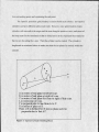

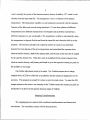

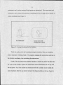


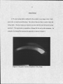


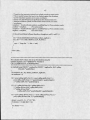

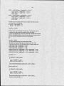


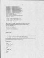


![[U4.63.01] Opérateur CALC_CHAR_SEISME](http://vs1.manualzilla.com/store/data/006375751_1-063455accbcbbe45927ff9adc15db97f-150x150.png)
![[U4.92.06] Procédure TEST_COMPOR](http://vs1.manualzilla.com/store/data/006372084_1-e6d02d726d72d0b2361fd399fef07ca0-150x150.png)