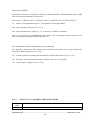
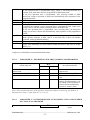
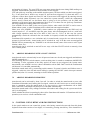
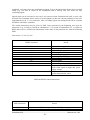
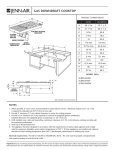
1
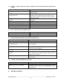
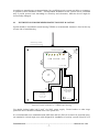
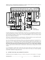
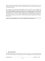
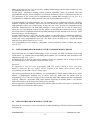
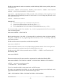
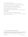
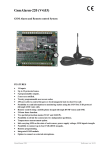
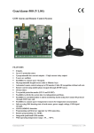
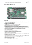
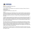
CONTROL AND MONITORING DEVICE
GsmAlarm-420
Remote control and monitoring via GSM network
FEATURES
•
•
•
•
•
•
•
•
•
•
•
Integrated GSM module.
4 inputs for door, motion, fire sensor connection.
3 programmable outputs for remote control.
Option to switch the protection mode on/off by short free call.
5 users are informed on the protected unit.
250 users able to control the gate or electromagnetic lock by short free call.
Info-carrying SMS on the state of each sensor, number of triggers, system mains voltage,
GSM signal strength.
Option to connect siren.
Option to connect external mic.
Remote programming.
Cheap maintenance.
Table of Contents
_______________________________________________________________________________
GsmAlarm-420
Software ver. 1.04
1
1. General Information ........................................................................................................................ 1
1.1. Safety Insrtuction ..................................................................................................................... 1
1.2. Package Content....................................................................................................................... 2
1.3. General Description ................................................................................................................. 3
2. Connectors and LEDs ..................................................................................................................... 4
2.1. Inputs Z1-Z5 ............................................................................................................................ 4
2.2. Microphone Connection Contacts ............................................................................................ 5
2.3. Outputs C1 and C2 ................................................................................................................... 5
2.4. Output BELL ........................................................................................................................... 5
2.5. Output AUX............................................................................................................................. 5
2.6. Contact B+ ............................................................................................................................... 5
2.7. Contacts POWER..................................................................................................................... 5
2.9. Contacts RESET ...................................................................................................................... 5
3. LED Indicators................................................................................................................................ 6
3.1. SIGNAL: Indicator of Signal Strength and GSM Module Operation Mode ............................. 6
3.2. Z1-Z4: Input Status Indicator ................................................................................................... 6
3.3. MODE: System Operation Mode Indicator .............................................................................. 6
3.4. ALARM: Alarm Mode Indicator ............................................................................................. 6
4. Installation ...................................................................................................................................... 7
4.1. Instruction for Premises Protection Installation........................................................................ 7
4.2. Instruction for Car alarm Installation ....................................................................................... 9
4.3. System Operation Set Up ....................................................................................................... 10
5. Programming ................................................................................................................................ 11
5.1. User Number Programming with Standard Mobile Phone ..................................................... 11
5.2. User Number Programming with SMS .................................................................................. 12
5.3. System Parameter Programming with SMS ........................................................................... 14
5.3.1. Protected Zones Z1-Z5 Parameter Programming ............................................................ 14
5.3.1.1. Parameter M ............................................................................................................ 15
5.3.1.2. Parameter A ............................................................................................................ 15
5.3.2. Programming of Output C1, C2, BELL and Common System Parameters E, F, T, U ... 16
5.3.2.1. Output C1, C2 and BELL Operation Mode .............................................................. 17
5.3.2.2. Parameter E : Informing User about Arming and Disarming .................................. 17
5.3.2.3. Parameter F : System Response to Incoming Calls and Number
of Calls in Alarm Mode ............................................................................................ 18
5.3.2.4. Parameter U : Reserve Battery Voltage ................................................................... 18
5.4. SMS Password Change .......................................................................................................... 18
6. Resetting System Parameters to Factory Defaults ........................................................................ 19
6.1. Premises Protection Mode Factory Defaults .......................................................................... 19
6.2. Vehicle Protection Mode Factory Defaults ............................................................................ 19
7. System Control ............................................................................................................................ 20
7.1. Arming/Disarming with ON/OFF Switch .............................................................................. 20
7.2. Arming/Disarming Remotely ................................................................................................. 20
7.3. Control Using DTMF and SMS Instructions .......................................................................... 20
8. Warranty ...................................................................................................................................... 23
9. Specifications ............................................................................................................................... 24
_______________________________________________________________________________
GsmAlarm-420
Software ver. 1.04
2
GENERAL INFORMATION
1.1 SAFETY INSTRUCTION
Important! Read and strictly follow all safety and operational instructions written in this user
manual, before using GsmAlarm-420 in order to guarantee safety and prevent possible injuries from
possible thermal and electric device failures for you and surrounding people.
Retain all safety and operational instructions for future reference during the whole operation lifetime
of device.
Device has two power supplies: main and reserve.
For premises protection:
Main: power transformer: I: 230V 50/60 Hz; II: (16–24)V ~ 1,2 A 50/60Hz;
Reserve: 12 V 1,2 Ah battery.
For car protection:
Main:12 V car battery;
Reserve: 6 V 1,2 Ah battery.
Device GsmAlarm 420 certifies required safety level of LST EN 60950-1:2003
standard.
All power supplies described above and connected to device must satisfy the
safety requirements of LST EN 60950 –1 standard!
Additional circuit breaker should be installed in AC electric power circuit to
protect from over-current and short circuits.
Only a qualified specialist possessing strong knowledge about general safety
requirements and technology of device can perform system installation works and
technical support.
In case of any device performance disorder only qualified specialist can repair it.
There are no parts you can change at place in the device.
ATTENTION!
EXPLOSION POSSIBLE USING WRONG KIND BATTERIES - NOT
RECOMMENDED BY MANUFACTURER.
DO NOT SWITCH POLES OF BATTERY BY ACCIDENT.
DO NOT SHORT CIRCUIT BATTERY POLES.
MAINTENANCE PERSONNEL WARNING!
TWO POLES OF AC ELECTRIC POWER SUPPLY.
POWER TRANSFORMER CUT-OUT IN NEUTRAL CABLE!
_______________________________________________________________________________
GsmAlarm-420
Software ver. 1.04
-1-
Disconnect device from AC power and reserve battery before performing any
installation or maintenance work.
It is forbidden to perform any device installation or maintenance work during
lightning!
Remote control and monitoring device GsmAlarm-420 has built-in radio transmitter operating on
GSM900 and GSM1800 networks.
Do not use the device where it can cause interferences and danger.
Do not arrange the device close to medical equipment and appliances.
Do not use the device in explosive environment.
Device is not resistant to moisture, chemical materials or mechanical damage.
This symbol on the product or on its packaging means that your electrical and electronic
equipment should be disposed at the end of life separately from your household wastes.
There are separate collection systems for recycling in EU. For more information, please
contact the local authority or the dealer where you purchased the product.
1.2 PACKAGE CONTENT
Device GsmAlarm-420....................................................................................... 1 pcs.
GSM antenna with magnetic fix and 2 m lead cable……………….................. 1 pcs.
Microphone with 1,5 m lead cable……….......................................................... 1 pcs.
Load resistors 2,2k ±5%...................................................................................... 5 pcs.
Clamping cable for accumulator connection……............................................... 1 pcs.
User‘s manual........................................................................................................1 pcs.
1.3 GENERAL DESCRIPTION
_______________________________________________________________________________
GsmAlarm-420
Software ver. 1.04
-2-
Four zone control and monitoring device GsmAlarm-420 can be used for protection of cars, boats,
houses, apartments, garages, and cottages. In the case of trespass of the protected zone GsmAlarm420, depending on the programmed system operation algorithm, switches the siren on, calls and
sends SMS messages to five users. User answers the call using his phone keypad (DTMF tones), can
listen, what is going on in the unit, SMS may be received, informing about the controlled zone state,
number of each zone activation.
GsmAlarm-420 has 2 (3, if siren is not used) programmable outputs, intended for remote control of
different devices. User can turn on/off heating, ventilation or lighting systems etc, by using his
mobile phone just by typing a relevant code or sending SMS to the control device.
Device works perfect for remote control of automated gates, fences and electromagnetic door locks.
In order to open the gate, user calls GsmAlarm-420 number. Then GsmAlarm-420 checks the caller’s
number in the list of programmed user numbers and in the case of positive find, switches on the gate
control device and cancels the call automatically. 250 users are able to control the gate.
The system answers only to the numbers programmed. If the system receives a call, coming not from
the user's phone, the call is immediately interrupted and the user is sent SMS, specifying the caller's
phone number. SMS messages are also sent to users in case of power loss and restoration.
You can check alarm operation by short call to GsmAlarm-420 number. If GsmAlarm-420 is
operative, the calling user gets a short confirmation call.
All GsmAlarm-420 parameters are programmed remotely, by sending SMS with relevant contents
with password.
2.
CONNECTORS AND LEDs
_______________________________________________________________________________
GsmAlarm-420
Software ver. 1.04
-3-
ANTENNA CO NNECTO R
L ED
SIGNAL
Z1
Z2
Z3
Indicators
Z4
MO DE
ALARM
GS M ALARM - 420
SIM CARD
GND Z1 Z2
Z3
Z4
Z5 M- M+ C1 C2
BELL
B+
PO WER
AUX
GND
-"
Sensor Inputs
Microphone Programmable
Input
O utputs
DC Supply O utput
(12V or 6V)
Red
"
Blue
RESET
Contact
Power Supply
Input AC/DC,
16-24V
+
Backup
Battery
Input
GsmAlarm-420 connection contacts and LED indicators
2.1
INPUTS Z1-Z5
2.2k
PROCESSOR +3V
GND
Z
Inputs Z1-Z5 are used to connect sensors of protected zones. The
inputs can operate in a “loaded input” mode or in a “zero-one”
mode (see ch. 5.3.1.2).
The “loaded input” mode is
recommended to be used for protection of premises. In this case
all the inputs have to be loaded with 2.2k resistors. The system
becomes triggered both when the monitored input circuit is
broken as well as when it is short-circuited.
In the second case the system is triggered after breaking or shortcircuiting of the monitored input circuit (depending on the
programmed "active" level).
Equivalent diagram of input
Input Z5 is used to arm/disarm the system. System can be armed by applying active level to Z5. After
the delay time passes, the system starts checking the monitored inputs; in the case of alarm it
activates the siren, calls and sends SMSs. After Z5 level is changed, the system is disarmed and
responds to no zone changes (except when the monitored zone is operative 24 hours per day).
2.2 MICROPHONE CONNECTION CONTACTS M- M+
_______________________________________________________________________________
GsmAlarm-420
Software ver. 1.04
-4-
Contacts M- and M+ are used to connect external microphone. Connect black/ white wire to contact
M+, black to M-. Try to install mic as far as possible from GSM antenna. If wire of the mic is long
(over 2 m), it is recommended to use shielded twisted pair cable. Connect shield to GND contact.
Mic is switched on by DTMF instruction 66* in the conversation mode (see ch. 7.3).
2.3 OUTPUTS C1 & C2
33
C
Programmable outputs C1 and C2 are used to connect remotely controlled devices.
Relays with 12V operation voltage and current not exceeding 150 mA max, are
recommended for device control.
Output operation modes are described in ch. 5.3.2.1
GND
C1-C4 equivalent diagram
2.4 OUTPUT BELL
BELL
The BELL output is used to connect audio siren or extra-commutated device (see
ch. 4.1 and 4.2).
GND
Commutated current may reach 0.6 A max.
Equivalent diagram of BELL OUTPUT
2.5
OUTPUT AUX
AUX output is used to supply power external devices (fire, motion sensors) and is short-circuitprotected. This output has voltage +13.7 V or +6.8V (depending on the system parameter U, see ch.
5.3.2 and 6.2). Load current is 1 A max.
2.6 CONTACT B+
“+” terminal of reserve battery is connected to contact B+. Max capacity of the battery is 1.2 Ah.
12 V battery is used in the premises protection mode.
It is recommended to use 6 V battery for car protection. In this case switch GsmAlarm-420 to 6 V
mode (see par. 5.3.2 and 6.2).
2.7 CONTACTS POWER
Input POWER is used to connect secondary winding of power supply transformer with voltage
between 16V and 24V (or 12V DC in car protection mode).
2.8 CONTACTS RESET
RESET contacts are used to restore factory default parameters (see. ch. 6).
3.
LED INDICATORS
_______________________________________________________________________________
GsmAlarm-420
Software ver. 1.04
-5-
3.1 SIGNAL: INDICATOR OF SIGNAL STRENGTH AND GSM MODULE OPERATION
MODE
Indicator state
Out.
Continuously On.
Blinking more frequently than once a
second.
Blinks 5 times, short break after.
Blinks 4 times, short break after.
Blinks 3 times, short break after.
Blinks 2 times, short break after.
Blinks once, short break after.
Explanation
GSM module is not in use. No power supply or
system failure.
There is no GSM operator network registration.
Possible causes: SIM card PIN code request is not
deactivated, antenna not connected or poor network
connection quality.
GSM module is in use: outgoing call or SMS is
being sent.
Very good signal.
Good signal.
Satisfactory connection.
Weak connection.
Poor connection.
3.2 Z1-Z4: INPUT STATUS INDICATOR
Indicator state
Out.
Continuously On.
Explanation
Input is not triggered
Input is triggered
3.3 MODE: SYSTEM OPERATION MODE INDICATOR
Indicator state
Out.
Continuously On.
On with short breaks.
Blinking with low frequency (once in
2-3 sec.).
Blinking more frequently than once a
second.
Blinking very rapidly for 2-3 sec.
Explanation
No power supply or system failure.
System is operative, disarmed, no zone sensors have
been triggered.
System is operative, disarmed, but one or more zone
sensors have been triggered.
System is operating in armed mode.
System is in alarm state, siren is active, call or SMS is
sent. If SMS is sent, indicator blinks a little bit slower
(about twice a second).
SMS instruction or DTMF command receipt
confirmation.
3.4 ALARM: ALARM MODE INDICATOR
Indicator state
Blinks at a permament rate.
Blinks twice every 2-3 seconds.
4.
Explanation
System is in alarm state, call is made or SMS sent.
ALRNR1 number has not been programmed. In order
GsmAlarm could make calls, this number need to be
programmed!
INSTALLATION
_______________________________________________________________________________
GsmAlarm-420
Software ver. 1.04
-6-
According to manufacturer recommendations, hire qualified security system specialist (or company)
to perform system installation works. Self-dependent installation of the system can be performed
only if person possess basic knowledge in electricity and electronics, otherwise device might be
irrecoverably damaged.
4.1
INSTRUCTION FOR PREMISES PROTECTION INSTALLATION
System should be assembled in metal housing 7TRP20 as recommended. Antenna is fixed on the top
of outer side of metal housing.
Metal Housing (7/T RP20)
Housing
Fixt ure
Holes
4 x 5 mm
ANT ENNA CONNECT OR
SIGNAL
MODE
Z1
Z2
Z3
ALARM
Z4
GSM ALARM - 420
B+ GND POWER
Cable
Hole
AC 230V
BLUE
RED
+
-
RESERVE
BAT T ERY
AC 18V
P OWER SUPPLY
T RANSFORMER
(T RP 20/01)
SAUGIKLIS
AC 12V 1.2Ah
(CT 1.2-12)
T 0.16A
LSTEN 60950
Layout of system elements in 7/TRP20 type housing
Use double isolated cable 3x0,75 mm2 for 230V power supply. Circuit breaker or other surge
protection device should be installed in the 230V power line.
It is recommended to use standard motion (SRP-300) and fire (EA318-4) sensors in protected zones,
use standard 6-8 wired single core cable designed for installation of security systems. Siren DC12V
_______________________________________________________________________________
GsmAlarm-420
Software ver. 1.04
-7-
500mA (S-108) is recommended for sound alarm, use double isolated cable 2x0,75 mm2 to connect it
to the system. Reserve battery must be PB-acid (CT1,2-12).
+
Movement
12V
Fire +
DC12V
500mA max.
Red
Relay K2
+
AC 230V
-
DC12V 150mA max
-
Backup Battery
12V 1.2Ah
+
2.2k
Sensors 12V
+
External Indicator LED
Switch ON-OFF
Windows Contacts
Bel l
Power Supply
Transformer
2.2k
2.2k
2.2k
2.2k
2.2k
-
Microphone
Door Contacts
B+
BELL
PO WER
GND
AUX
AC 16-24 V
~1.2 A
Z5 M- M+ C1 C2
Blue
Z4
Black/White
Z3
Black
GND Z1 Z2
Relay K1
DC12V 150mA max
Remote
Controlle d Relays
Wiring diagram for premise protection
In armed mode inputs Z1-Z5 must be loaded with 2.2k resistors. It is recommended to install resistors
in the most distant point of the line, close to sensor. This will guarantee alarm activation in case of
short circuiting or breaking of sensor circuit. If external LED MODE is not in use, remote control
relay can be connected to contact C1.
LED must be installed withindoors in a prominent place. LED state indicates system operation mode
status, if all protected zones are closed before switching on armed mode.
User can arm/ disarm system with short call from user mobile phone (parameter F should be F51 or
F41, see ch. 5.3.2.3). Please note, if trying to call the system in alarm state, deactivation is not
possible, therefore it is recommended to use switch ON-OFF designed for activation/ deactivation of
armed mode. The switch can be connected to any zone instead of sensor contacts. Zone, designated
for sensor connection must operate in ON/OFF mode (A33, see ch. 5.3.1.2). Armed mode is activated
if there is open circuit in switch contacts. Armed mode is deactivated by closing circuit in switch
contacts.
It is recommended to install remote control relays into sockets which can be easily fixed to metal
housing. Operating current of relay coil can not exceed 150mA max. Relays are selected depending
on desirable commutative voltage and current.
4.2 INSTRUCTION FOR CAR ALARM INSTALLATION
GsmAlarm-420 can be installed in all types of vehicles with petrol or diesel engines, 12V negative
_______________________________________________________________________________
GsmAlarm-420
Software ver. 1.04
-8-
earth batteries (negative pole connected to vehicle frame). System must be installed in the passenger
compartment of vehicle according to the given instructions of installation.
Z5
M-
C1
Microphone
Exte rnal Indicator LED
,,GND"
C2
Relay 1
Relay 2
B+
AUX
Blk/Whit
ON/OFF
Shock
Boot
Bonnet
Door
Sensors
M+
+
PO WER
GND
+ Backup Battery
6V 1.2Ah max.
1A
Z4
DC 6V 0.6A max.
Z3
Bell Or Relay
Z2
Blk
Z1
-
2.2k
+
,,GND"
Fuse
BELL
GND
+
Car Batte ry
12V
DC 6V 150mA max.
DC 6V 150mA max
Re mote Controlled Re lays
Wiring diagram for vehicle protection
GsmAlarm-420 must be installed inside the vehicle passenger compartment in difficult access area.
Mount the device in place free from penetration of moisture and other corrosion - causing materials,
as far away as possible from heating elements in the passenger compartment and sources of
electromagnetic interference (vehicle computer, conditioner, block of relays). Avoid mounting
system unit directly onto metal parts of vehicle to prevent accumulation of condensate in the system
unit. Mount “GsmAlarm-420” in a way wire connectors are going from the bottom side of the unit.
Avoid placing wires adjacent to moving or hot parts of vehicle. Reserve 6V battery must be accurately
fixed close to “GsmAlarm-420” device. Use plastic fixing belts for fastening. Mount the battery in place
free from penetration of moisture and other corrosion - causing materials, as far away as possible
from heating elements in the passenger compartment. Operating voltage of battery must be 6 V,
system must operate in 6 V mode. Instructions for system reprogramming to vehicle mode described
in chapter 6.2.
Main power to GsmAlarm-420 is supplied (clamp „POWER“) from car battery through 1A standard
5x20 mm fuse, mounted in isolated block PTF/80A. Fuse must be mounted as close as possible to car
battery. Use heat (to +150 °C) and cold (to -60 °C) resistant isolated 0,56 mm² diameter red wire (SPEC
55) to connect „+“ to system power supply. Other system power supply clamp must be connected to car
frame “earth” in nearest most convenient point.
Connect inputs Z1-Z4 to relevant car contactors; input Z5 is used for system arming/disarming. All
outputs in the car mode are working in a zero-one mode; therefore no 2.2k resistor loads are needed.
6V battery supplies power to relay and siren (contact AUX).
4.3 SYSTEM OPERATION SET UP
SIM card is needed for GsmAlarm-420 operation, you may acquire it from any GSM service
provider.
_______________________________________________________________________________
GsmAlarm-420
Software ver. 1.04
-9-
Before inserting SIM card into GsmAlarm-420 SIM card holder set PIN code request off. It can be
performed simply inserting SIM card into any standard mobile phone and following certain phone
user manual instructions.
After system circuit is connected according diagrams showed in chapter 4.1 or 4.2, place SIM card
into GsmAlarm-420 SIM card holder, turn system power on, then wait till indicator SIGNAL will
start to blink periodically and indicator MODE will be constantly alight. In case SIGNAL is
constantly alight, check if SIM card‘s PIN code request is off and GSM antenna is connected. GSM
signal quality can be evaluated according the blinking frequency of SIGNAL indicator. Connection is
very good if it blinks 4 or 5 times with 2 seconds breaks after. SIGNAL indicator blinking fewer
times, indicates weaker connection. Position of GSM antenna might be changed in order to improve
signal quality.
Perform system programming when armed mode is disabled (ON/OFF contacts are closed). Protected
zones must be closed (indicators Z1 – Z4 are off, MODE and LED constantly alight).
5.
PROGRAMMING
GsmAlarm-420 parameters can be divided into two groups. First group – user phone numbers which
are stored in SIM card memory. User phone numbers can be programmed by using standard mobile
_______________________________________________________________________________
GsmAlarm-420
Software ver. 1.04
- 10 -
phone of any type (see ch. 5.2.1) or remotely, sending SMS message with the phone numbers of users
to GsmAlarm-420 (see ch. 5.2.2).
Second group – parameters, defining system operation algorithms, names of protected zones and
programmable outputs. These parameters are stored in the memory block of GsmAlarm-420 device.
The parameters of the system can be programmed by sending SMS message (see ch. 5.3). It is
recommended to change the SMS password at the end of programming (see ch. 5.4)
If GsmAlarm-420 is used for protection, five user numbers can be programmed: ALRNR1, ALRNR2,
ALRNR3, ALRNR4 and ALRNR5. These users can arm/ disarm the system, calls will be directed and
SMS messages will be sent to these users. If only one user exists, he must be programmed under
ALRNR1. GsmAlarm-420 will send SMS messages to this specific user in case of main power
supply loss or if an unknown number calls the system. If armed mode is turned on or off by turning
the switch ON/OFF GsmAlarm-420 dials and SMS messages are also directed to the first user. Other
four user numbers are not obligatory.
In case GsmAlarm-420 is used only for gate control it is not necessary to programme ALRNR1ALRNR5. Up to 250 user numbers, with the possibility to control the outputs C1, C2, and BELL with
a short call, can be programmed in this case. Any name can be ascribed to user. Output operation
mode has to be M04 or M05 (see ch. 5.3.2.1).
After programming of user numbers - programme system parameters, names of inputs and outputs
(see ch. 5.3).
5.1 USER NUMBER PROGRAMMING WITH STANDARD MOBILE PHONE
Insert SIM card into a standard mobile phone. Enter user name into SIM card number book using
capital letters e.g. ALRNR1 and corresponding phone number. We recommend enter the number with
international code. (E.g. +370....)
If GsmAlarm-420 is used for gate control, number of extra user numbers can be as large as fits into
the SIM card (up to 250). Any name can be ascribed to user.
Important:
It‘s important to note that while programming SIM card memory should be active (not phone
memory!). Otherwise the user number will be recorded in the mobile phone memory used for
programming and the SIM card will remain empty.
After having programmed all user numbers, it is recommended to check whether SMS service centre
number is programmed. Simplest way to check: send any SMS from the phone used for
programming. If it is sent successfully we can be sure that SMS centre number has been programmed
correctly. Otherwise, programme SMS centre number following the mobile phone’s user manual.
SMS centre number can be learnt from GSM service provider.
After completion of programming and checking whether SIM card PIN code request is switched off,
take the SIM card off from the mobile phone.
5.2 USER NUMBER PROGRAMMING WITH SMS
Switch on the system power source and wait for periodical blinking of SIGNAL indicator and MODE
constantly On.
_______________________________________________________________________________
GsmAlarm-420
Software ver. 1.04
- 11 -
In order to programme the main user numbers, send the following SMS from any mobile phone into
GsmAlarm-420:
AAAAAAAA ALRNR1:+3706123456789 ALRNR2:+3706123456789 ALRNR3:+3706123456789
ALRNR4:+37061234546789 ALRNR5:+3706123456789
AAAAAAAA: eight digit alphanumeric SMS password, which is obligatory in the beginning of each
SMS. Manufacturer-programmed password is AAAAAAAA. User can change the password on his
own desire (see ch.5.4).
ALRNR1 ... ALRNR5: user numbers.
IMPORTANT:
a) No characters/spaces can be used before the password;
b) No spaces are allowed before and after the colon;
c) Spaces must follow the password and each phone number;
d) It is recommended to enter user numbers with international code (e.g. +123…).
It is not necessarily to send all user numbers. E.g., in order to programme only the first user number,
send the following SMS:
AAAAAAAA ALRNR1:+3706123456789
Receipt and decrypting of the SMS by GsmAlarm-420 is confirmed by blink of indicator MODE.
The phone, which has sent the programming SMS, immediately receives a confirming SMS with
programmed numbers.
In order to delete unnecessary number, send the following SMS:
AAAAAAAA ALRNR2:N
Number ALRNR2 is deleted, user receives SMS with programmed numbers. In order to replace one
number with another, no separate instruction for deletion needs to be sent.
In order to receive SMS with programmed numbers ALRNR1 ... ALRNR5, send GsmAlarm-420
the following SMS:
AAAAAAAA NRINFO
Extra user numbers (only for gate control) are programmed by sending the following SMS:
AAAAAAAA ADDNR:+3701234567891 ADDNR:+3701234567892 ADDNR:+3701234567893
ADDNR: – new number entering instruction.
+3701234567891 – new user number.
Up to 8 user numbers might be programmed with one SMS message.
If number was programmed successfully, the user, who sent the message, receives SMS with newly
programmed number. In this case the confirmation message will be:
USR1:+3701234567891 USR2:+3701234567892 USR3:+3701234567893
_______________________________________________________________________________
GsmAlarm-420
Software ver. 1.04
- 12 -
USR1 – name, assigned to the new number.
In order to delete the extra user number, send to GsmAlarm-420 the following message:
AAAAAAAA DELNR:+3701234567891 DELNR:+3701234567892 DELNR:+3701234567893
Specified numbers will be deleted and user receives the confirming SMS:
DELET:+3701234567891 DELET:+3701234567892 DELET:+3701234567893
Up to 8 user numbers might be deleted with one SMS message.
In order to receive SMS message indicating all programmed numbers, following message must be
sent to GsmAlarm-420:
AAAAAAAA NRLIST
User receives one or more SMS messages with all programmed numbers listed.
Note! Up to 8 user numbers can be sent in one SMS message. If 250 numbers are programmed
GsmAlarm-420 will send 32 SMS messages!
5.3
SYSTEM PARAMETER PROGRAMMING WITH SMS
All GsmAlarm-420 input and output operation modes, delay times and names can be programmed
with the help of SMS. First of all, it is recommended to receive SMS with programmed parameters
and then to send the same SMS with corrected parameters back to GsmAlarm-420.
_______________________________________________________________________________
GsmAlarm-420
Software ver. 1.04
- 13 -
5.3.1
PROTECTED ZONES Z1-Z5 PARAMETER PROGRAMMING
In order to receive SMS with input Z1 – Z5 parameters, send GsmAlarm-420 the following SMS:
AAAAAAAA ZPARAM
SMS can be sent from any GSM phone, not necessarily the user’s. GsmAlarm-420 confirms
receiving the message with frequent blinking of MODE indicator and sends SMS message including
input parameters Z1- Z5. Received message will look as follows:
AAAAAAAA Z1:M70T20A20 Door, Z2:M70T00A20 Windows, Z3:M70T00A20 Movement,
Z4:M71T00A20 Fire, Z5:M02T00A20 ON-OFF,
AAAAAAAA: password.
Z1:
protected zone input number.
M70:
parameter defines system response to the violation of protected zone and which users are
informed if certain zone sensors are triggered (see ch. 5.3.1.1).
T20:
delay time after triggering (in seconds), if system is in armed mode. After relevant input is
triggered, the system switches siren on and sends SMS only after expiration of the given delay time.
Possible values: 0...99 seconds.
A20:
input operation mode, parameter A (see ch. 5.3.1.2).
Door, Windows, Movement, Fire, ON-OFF: input names, which are seen in the SMS after alarm
triggering. User can change the name of zone under his own discretion. Maximum number of name
characters: 11.
5.3.1.1
PARAMETER M
Alarm state after input triggering
MXY
Input operation mode
X
Y
All functions, described below, are
0
0
Input with programmable delay
deactivated.
time. *
_______________________________________________________________________________
GsmAlarm-420
Software ver. 1.04
- 14 -
Siren is operating.
Calling.
Siren is operating and calling.
Sending SMS message.
Siren is operating and sending SMS
message.
Calling and sending SMS message.
Siren is operating, calling and
sending SMS message.
1
2
3
4
5
1
2
3
-
6
7
-
24 hour input. **
Fire sensor connection input ***
ON/OFF zone. ****
* Input with programmable delay time. After relevant zone is being triggered, the system will switch
alarm on only if armed mode is active, after expiration of the given delay time T.
** 24 hour input. After relevant zone is being triggered, the system switches alarm on with no respect
to armed mode (ON/OFF), siren operates constantly, delay time is ignored.
*** Fire zone mode. 24 hour input, siren is operating with interruptions.
**** Zone ON/OFF. Mode designated to turn armed mode on/off .
5.3.1.2
PARAMETER A
Input triggering conditions
Zero-one mode, active level: low
(GND).
Zero-one mode, active level: high
(+12V or open contact).
Loaded input mode, 2.2k load
required.
AXY
Y
0
All (ALRNR1-ALRNR5).
1
1
Only user ALRNR1.
2
2
Only user ALRNR2.
3
4
5
6
7
Only user ALRNR3.
Only user ALRNR4.
Only user ALRNR5.
Users ALRNR1 and ALRNR2.
Users ALRNR1, ALRNR2 and
ALRNR3.
Users ALRNR1, ALRNR2,
ALRNR3 and ALRNR4.
8
5.3.2
Users, getting information about
zone violation
X
0
PROGRAMMING OF OUTPUT C1, C2, BELL AND COMMON SYSTEM
PARAMETERS E, F, T, U
In order to receive SMS message including output C1, C2 and BELL and common system
parameters, send GsmAlarm-420 the following message:
_______________________________________________________________________________
GsmAlarm-420
Software ver. 1.04
- 15 -
AAAAAAAA CPARAM
Receiving the message is confirmed by blinking of indicator MODE of GsmAlarm-420 device, SMS
with current system parameters is being sent:
AAAAAAAA C1:M02T05 OutC1, C2:M05T05 OutC2, C3:M06T02 Siren, PR:E24F52T20U12,
C1: number of programmable output. C3 corresponds to siren output BELL.
M02: output operation mode (see ch. 5.3.2.1).
T05: output operation time. Outputs C1, C2: in seconds, C3 (BELL): in minutes.
OutC1, OutC2 and Siren: programmable output names. User can change the name under his own
discretion. Maximum number of name characters: 11.
PR: command for common system parameters programming.
E24: method to inform user about armed mode activation/ deactivation. User can be informed by
short call or SMS message (see ch. 5.3.2.2).
F52: system response to incoming calls and number of calls in alarm state (see ch. 5.3.2.3).
T20: delay time after armed mode activation. Possible values: 00 – 99 seconds.
U12: reserve battery voltage. (see ch. 5.3.2.4.)
5.3.2.1
Output
mode
M00
OUTPUT C1, C2 AND BELL OPERATION MODE
Explanation of operation
Not in use.
_______________________________________________________________________________
GsmAlarm-420
Software ver. 1.04
- 16 -
M01
M02
M03
M04
M05
M06
M07
Output controlled by DTMF or SMS instructions.
If zero operation time is programmed (T00), output is activated/deactivated and
remains in the same state after receiving DTMF or SMS instruction.
If not zero operation time is programmed, after receiving DTMF or SMS
instruction, output is activated, it deactivates automatically after expiration of the
programmed time.
LED mode. Output is in operation together with MODE indicator.
Output is activated, when system is armed. Open contact, when system is disarmed.
Control by short call without number recognition function. Output is activated with
a call from any number. If zero operation time is programmed (T00), output state
changes after a call and remains unchanged till the next short call.
If not zero operation time is programmed, after receiving short call instruction
output is activated, it deactivates automatically after expiration of the programmed
period.
Control by short call with number recognition function (gate control mode). This
mode operates analogue to M04, thus it is activated only if short call number
coincides with programmed numbers.
Siren mode. Valid only for output BELL (C3).
Siren mode with audible confirmation. After arming, one short audible sound is
heard. After disarming, two short audible sounds are heard. Valid only for output
BELL (C3).
Outputs are controllable in armed and disarmed modes.
5.3.2.2
PARAMETER E : INFORMING USER ABOUT ARMING AND DISARMING
System response to switching the
armed mode ON
All functions below are
deactivated.
User is informed by SMS.
User is informed with a short call.
EXY
X
Y
0
0
1
2
1
2
4
System response to switching
the armed mode OFF
All functions below are
deactivated.
User is informed by SMS.
User is informed with a short
call.
If during the period of one
minute after disarming by call
no change in the input state is
found, system automatically
returns to “armed” mode.
Note! If several functions have to be operative, sum of the numbers is used. E.g.: for all three Y
functions to be active, Y value must be 7 (1+2+4=7).
5.3.2.3
PARAMETER F : SYSTEM RESPONSE TO INCOMING CALLS AND NUMBER
OF CALLS IN ALARM MODE
System response to incoming call
FXY
Number of the calls in alarm
mode
_______________________________________________________________________________
GsmAlarm-420
Software ver. 1.04
- 17 -
X
0
1
Y
0
1
If calling from user‘s number, after
3-4 calls the system will pick up,
armed mode will remain on.
2
2
After alarm triggering, users
will be called twice.
Armed mode is activated after user’s
short call.
4
4
If call received not from
ALRNR1-ALRNR5, thus the
calling number is in SIM card
(gate control mode), system
answers the call after 3-4
signals, and user can control
the system with DTMF
instructions. Call
automatically cancelled after
1 minute passes.
All functions below are deactivated.
If a call is received from unknown
caller, user ALRNR1 will receive a
SMS with caller‘s number.
After alarm triggering, users
will be called once.
Note! If several functions have to be operative, sum of the numbers is used.
E.g.: for all three X functions to be active, X value must be 7 (1+2+4=7).
5.3.2.4
PARAMETER U : RESERVE BATTETY VOLTAGE
In the case of use of GsmAlarm-420 for car protection, it is recommended to use not 12V, but 6V
reserve battery. This will assure reliable charge of reserve battery, independently of the car battery
voltage.
U12: system operates in 12V (premise protection) mode, reserve battery voltage 12V
U06: system operates in 6V (car protection) mode, reserve battery voltage is 6V.
5.4
SMS PASSWORD CHANGE
In order to change manufacturer-programmed SMS password, send GsmAlarm the following
message:
AAAAAAAA PASSW:ABCDefgh
AAAAAAAA – old SMS password.
PASSW – password changing instruction.
ABCDefgh – new SMS password. Password must be 8 characters long!
Note! No characters/spaces can be used before password, space must follow the password.
If programming instruction is executed successfully, user gets a confirming SMS message with the
new SMS password.
6.
RESETTING SYSTEM PARAMETERS TO FACTORY DEFAULTS
In order to return all system parameters back to default settings, connect contacts RESET with the
help of flat screwdriver and wait till LEDs Z1-Z4, MODE and ALARM are on (5-6 seconds). During
_______________________________________________________________________________
GsmAlarm-420
Software ver. 1.04
- 18 -
such connection system has to be powered. System parameters are set to values denoted in chapter
6.1.
Only the parameters stored in the internal memory module system can be reprogrammed using this
method. User umbers stored in SIM card will not be erased.
6.1 PREMISES PROTECTION MODE FACTORY DEFAULTS
Input
Z1
Z2
Z3
Z4
Z5
Output
C1
C2
C3 (BELL)
SMS Password
AAAAAAAA
Input parameters
Parameter M
Delay time T
Parameter A
M70
T20 (sec.)
A20
M70
T00 (sec.)
A20
M70
T00 (sec.)
A20
M72
T00 (sec.)
A20
M03
T00 (sec.)
A20
Output parameters
Name
Parameter M
Operation time T
OutC1
M02
T05 (sec.)
OutC2
M05
T05 (sec.)
Siren
M06
T02 (min.)
Common system parameters
Parameter E
Parameter F
Delay time T
Parameter U
E24
F52
T20 (sec.)
U12
Name
Durys
Langai
Judesio
Gaisro
ON/OFF
6.2 CAR PROTECTION MODE FACTORY DEFAULTS
In order to program car mode parameters:
a) return to default settings as already described (connect RESET contacts);
b) send GsmAlarm-420 message AAAAAAAA CPARAM and receive SMS with programmed
parameters;
c) change parameter U12 into U06 and send the same SMS to GsmAlarm-420.
Input parameters
Parameter M
Delay time T
Parameter A
M70
T00 (sec.)
A00
M70
T00 (sec.)
A00
M70
T00 (sec.)
A00
M70
T00 (sec.)
A00
M03
T00 (sec.)
A00
Output parameters
Output
Name
Parameter M
Operation time T
C1
OutC1
M02
T05 (sec.)
C2
OutC2
M05
T05 (sec.)
C3 (BELL)
Siren
M06
T02 (min.)
Common system parameters
SMS Slaptažodis
Parameter E
Parameter F
Delay time T
Parameter U
AAAAAAAA
E24
F52
T06 (sec.)
U06
Input
Z1
Z2
Z3
Z4
Z5
7.
Name
Door
Bonnet
Boot
Shock
ON/OFF
SYSTEM CONTROL
Five users can fully control GsmAlarm-420: ALRNR1 - ALRNR5. In the case of violation of any area,
these users are called in a row. If neither responds, all users are sent SMS with triggered area name
_______________________________________________________________________________
GsmAlarm-420
Software ver. 1.04
- 19 -
and number of triggers. The word YES near area name means that the area during SMS sending was
triggered. Number in the parenthesis shows number of area triggers.
User who picks up, according to the audible sound sequence, can learn which area has been triggered,
E.g., if one short tone is heard every second, Z1 area has been triggered, if 1 short and after a 1 s
sequence of three short signals are heard, Z1 and Z3 areas nave been triggered. By entering relevant
code on mobile phone keyboard, user can control the system remotely: switch the commutated
devices on/off, switch mic on and listen what is going on in the premises, ask for SMS with
parameters of protected areas and commutated devices etc. If at least one user picks up, GsmAlarm420 stops calling and sending SMS to the rest users.
User ALRNR1 receives SMS, in the case of power failure, when switch ON/OFF is used to arm or
disarm alarm system, or when GsmAlarm-420 is called from unrecognised number.
Other users (not ALRNR1 ... ALRNR5), whose numbers are programmed in the SIM card, can
control outputs C1, C2 and BELL (open the gates, doors with electromagnetic lock etc.) with brief
calls. Output operation mode has to be M04 or M05 (see ch. 5.3.2.1) In this case the system
automatically cancels the call and in the case number is accepted, switches the controlled device on
or off.
GsmAlarm-420 responds to area violations only in armed mode (except the case when the input
operates in 24-hour mode). Armed mode can be switched on only if all the areas are untriggerred
(MODE LED is permanently on). If MODE is on with short breaks, some of the areas is active (open
window, doors, etc.).
Armed mode can be switched on and off in two ways: with the ON/OFF switch or remotely, from
user‘s mobile phone.
7.1
ARMING/ DISARMING WITH ON/OFF SWITCH
Armed mode can be activated only in case all protected zones are closed (not triggered) and indicator
MODE constantly on.
After breaking ON/OFF switch contacts, switch-on delay time is started to countdown (MODE LED
is blinking). If after expiration of the delay period, all zones are not triggered, the system enters
armed mode, user ALRNR1 receives a short confirmation call or SMS. Don’t cancel the confirmation
call because it is cancelled automatically.
Switch the armed mode off, by connecting switch contacts. If system is inactive and 24-hour zone is
triggered, switch the siren off and cancel calling by putting the ON/OFF switch into open contacts
position and, after 2-3 seconds, returning to closed contacts position.
7.2
ARMING/ DISARMING REMOTELY
Armed mode can be activated by short, free call. In order to switch the armed mode on, user calls
GsmAlarm-420 number and, hearing the first signal, cancels the call. In this case no switch-on delay
time is countdown. After the armed mode is on, user receives a short confirmation call or SMS.
Don’t cancel the confirmation call because it is cancelled automatically.
Switch the armed mode off by calling GsmAlarm-420 number and waiting for the system cancels the
call (3-4 call signals).
Check whether the alarm is operating by short call to GsmAlarm-420 number. If GsmAlarm-420 is in
operation, user receives a short confirmation call.
7.3 CONTROL USING DTMF AND SMS INSTRUCTIONS
In the speech mode user can control the system, after having entered relevant code from his phone
keyboard. Instruction consists of two digits, it is entered by pressing asterisk key. If the instruction is
_______________________________________________________________________________
GsmAlarm-420
Software ver. 1.04
- 20 -
completed, user hears three tone confirmation signals. If given instruction has already been executed
earlier (e.g. you want to switch on the commutator, that is already ON), user hears one tone
confirming signal.
Speech mode can be activated in two ways: user answers when GsmAlarm-420 calls, or user calls
and waits for GsmAlarm-420 to answer (3-4 call signals). In this case relevant parameter F has to be
programmed (see ch. 5.3.2.3), otherwise, after 3-4 calling signals, the arming mode will be switched
off and the call will be cancelled.
The control instructions may be given by SMS. Insert password in the beginning, then type the
instruction. E.g., in order to switch on commutator C1, to switch off commutator C2, to switch on
BELL and to receive a SMS with information on the status of the protected site, send the following
SMS:
AAAAAAAA 11* 20* 33* 99*
DTMF command
Result
00*
11*
10*
22*
20*
33*
30*
55*
66*
60*
88*
System disarming
Activating output C1
Disactivating output C1
Activating output C2
Disactivating output C2
Activating output BELL
Disactivating output BELL
System arming
Activating external microphone
Disactivating external microphone
Request to send SMS with information
about GSM signal strength and power
supply voltage.
Request to send SMS about state of the
system and protected zones.
99*
SMS and DTMF control instructions
SMS instruction
Result
ZPARAM
Request to send SMS message with input Z1-Z5 parameters.
CPARAM
Request to send SMS message with output C1, C2 and BELL parameters.
_______________________________________________________________________________
GsmAlarm-420
Software ver. 1.04
- 21 -
NRINFO
Request to send SMS message with user numbers of security system
ALRNR1 – ALRNR5.
SMS password change instruction.
PASSW:
ALRNR1:
ALRNR2:
ALRNR3:
ALRNR4:
ALRNR5:
ADDNR:
DELNR:
NRLIST
System users number programming instructions.
Gate control mode users number programming instructions.
Gate control mode users number erasing instructions.
Request to send SMS message (messages) with all numbers stored in SIM
card.
SMS instructions, for system programming and diagnostics
8.
WARRANTY
MANUFACTURER AND DISTRIBUTOR is not responsible for possible theft from GsmAlarm-420
protected premises or vehicle. GSM service operators are not associated to company “UAB
Elektroninės Technologijos”, therefore, company takes no responsibility for GSM network services,
coverage and functioning.
_______________________________________________________________________________
GsmAlarm-420
Software ver. 1.04
- 22 -
GsmAlarm-420 system PROVIDED with 24 month warranty. Warranty period starts with purchase
date. If there are no purchasing documents, period counted starting from system manufacturing date
(dated on security system identification label). Warranty is not valid if system: is reconstructed;
wrongly assembled; used not on purpose; mechanical, chemical, electric damage and in other cases
that are not related with GsmAlarm-420 manufacturing defects are seen.
If security system is not operating properly or breaks down, for guarantee or post-guarantee service,
please contact company that performed assembling and installation of the system. Practice shows
that main system operation failure reason is incorrectly performed system assembling.
Company “Elektroninės technologijos“ declares, that product “GsmAlarm-420” satisfies all essential
requirements of standard EN 60950–1:2003 following European Union directive 2006/95EC.
9.
SPECIFICATIONS
GSM MODULE
Operation frequency
900/1800/1900 MHz
_______________________________________________________________________________
GsmAlarm-420
Software ver. 1.04
- 23 -
MAIN POWER SUPPLY (connected to terminal “AC “)
Power supply voltage in premises protection mode
Frequency
AC Power supply voltage in car protection mode
Maximum current in premises protection mode
Maximum current in car protection mode
AC 16-24V
50/60Hz
DC 12V
~1.2A max
1.2A max
RESERVE BATTERY (connected to terminals “B+ “ and “GND“)
Voltage in premises protection mode
Voltage in car protection mode
Reserve battery type
Reserve battery capacity
DC 12V
DC 6V
PB - acid
1.2 Ah max
OUTPUT“AUX “ (FOR EXTERNAL DEVICES)
Output voltage in premises protection mode
Output voltage in car protection mode
Maximum current
Short circuit protection triggering current
DC 12V
DC 6V
1 A max
2 A max
SIREN OUTPUT “BELL” (C3)
Maximum current
Output active (siren is on)
Output non-active (siren is off)
0.6 A max
Connected to GND
Open contact
PROGRAMMABLE OUTPUTS C1, C2
Maximum current
Output active
Output non-active
150 mA max
Connected to GND
Open contact
INPUTS Z1 – Z5
Load resistance (“loaded input“ mode only)
2,2 kΩ
Ω , ±10 %
POWER CONSUMPTION (without external sensors and keypad)
Non-activated state
Call, sending SMS or speech mode
40 mA max
300 mA max
OPERATING TEMPERATURE
DIMENSIONS
-20°C…+55°C
135x85x35 mm
© ELEKTRONINĖS TECHNOLOGIJOS
http://www.eltech.lt
_______________________________________________________________________________
GsmAlarm-420
Software ver. 1.04
- 24 -