1
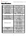
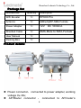
Shenzhen Ledmate Technology Co., Ltd.
2.4GHz 4W Wireless Signal Booster
Quick Installation Guide
Model Name : SW2430-003
1
Shenzhen Ledmate Technology Co., Ltd.
Features
�
4W
Max.
output
power,
enlarge
wireless
router/wireless LAN signal coverage range quickly
�
10dB-17dB adjustable gain, wide range input power,
high compatibility, support variety of formal wireless
AP/Router/LAN .
�
2.5dB min. Low noise figure, improve the receiving
capacity largely
�
Stable performance, low calorific value, 24hours
ongoing power-on support
�
Duplex amplified between receiving and transmitting,
synchronization switch in high speed,
No loss
communication guaranteed.
�
Easy and fast installation, no more software.
�
High linearity power amplifier, low signal distortion
2
Shenzhen Ledmate Technology Co., Ltd.
Specification:
Frequency
Duplex mode
2400-2483.5MHz
TDD
Signal standard
Input power
IEEE 802.11b/g/n
3dBm~26dBm
36dBm±1(4/5W)
Max output
Uplink gain
Down link gain
15±1dB
10dB~17dB adjustable
(minimum step:1dB)
≦2.5dB
<1uS
9V-36V
Noise figure
Time delay
Working voltage
9V,1500mA
12V,1000mA
15V,800mA
Working current
18V,600mA
24V,500mA
Temperature
36V,400mA
-25°C to + 60°C
Size
190*138*61 mm
Connector for booster
SMA female
Connector for antenna
RP-SMA male
3
Shenzhen Ledmate Technology Co., Ltd.
Package list
Accessories
Quantity
Description
WiFi Booster
1×
RF600 Pro
Antenna
1×
6dBiwhipRP-SMA Female
Power Adapter
1×
12V
Shielded Cable
1×
SMA-Male to SMA-Female
User Manual
1×
Packing Box
1×
DC 1000mA
Product detai
ls:
details:
� Power connector:connected to power adapter, working
voltage 9v-36v;
� AP/Router connector : connected to AP/router’s
4
Shenzhen Ledmate Technology Co., Ltd.
connector for antenna;
� Antenna connector:connected to antenna;
� Indicator : weak light when no data transmission , the
more data transmission, the more frequent flickers.
Installation Guide:
Please follow the steps 1~4 to install the device. When
disconnect, please unplug the power adapter first.
Attention:
�
Keep at least 1m distance between Wi-Fi Booster
antenna and any other 2.4G wireless products,
5
Shenzhen Ledmate Technology Co., Ltd.
Otherwise may result in equipment malfunction or
damage.
�
Do not use it where the place surrounded by a
large number of metals.which will make the
electromagnetic signal blocked.
�
If the user install antenna in the high location, you
need to take protection measures for lightning.
�
In any case, do not turn on the Wi-Fi without
antenna or remove it when working, otherwise
may damage the Wi-Fi Booster.
Attachment 1:
The adjustment method of the Downlink Gain
There are 4 switches in the case, switch 1-3 are used to
control the down link gain Switch 4 is for mode selection,default
configure is ON for Mode of internal auto detection;
If need switch to Mode of external control, please consult us,
this mode not recommendable for common customers .
The black points mark the position of switches
6
Shenzhen Ledmate Technology Co., Ltd.
Status
Downlink Gain
Status
Downlink Gain
11 dB
14dB
12 dB
15 dB
13 dB
16 dB
14 dB
17 dB
Launch the gain adjustment notice:
This Products can adjust the gain range from 10dB to 17dBto suitable
for different type and power of
wireless router,AP,LAN to ensure a better
performance.
The Downlink gain is too high may cause the booster not work
correctly.The wireless link can not be successfully connected,or even lead
to the damage of the booster.
The default Downlink gain is 13dB,it is not the higher the better .You
must ensure that the final transmit power must not be larger than
36dBm(4W).
The maximum output power of the booster is 36dBm(4w),default gain
is 13dB , the max output power is 23dBm , that is to say
7
Shenzhen Ledmate Technology Co., Ltd.
23dBm+13dB=36dBm ( 4w ) .So you need to reduce the Downlink gain
when it’s combined with a high-power AP/router and increase the Downlink
gain when it’s connect with a low-power AP/router.
The reference Downlink gain setting can be according to the following
table:
The transmitting power
The reference
The final transmission power
of AP/Router
Downlink gain
of the booster
>26dBm (Dangerous)
10dB
26dBm
10dB
36dBm
25dBm
10dB - 11dB
≤25+11=36dBm
24dBm
10dB - 12dB
≤24+12=36dBm
23dBm
10dB - 13dB
≤23+13=36dBm
22dBm
10dB - 14dB
≤22+14=36dBm
21dBm
10dB - 15dB
≤21+15=36dBm
20dBm
10dB - 16dB
≤20+16=36dBm
19dBm
10dB - 17dB
≤19+17=36dBm
≤18dBm
10dB - 17dB
≤18+17=35dBm
8
36dBm (Signal Distortion)