1
PiccoLink
RF600
User’s Manual
®
1
CONTENT
SYSTEM................................................................................................................................................................2
PRINCIPLES OF OPERATION .................................................................................................................................2
COMMUNICATION BETWEEN THE BASE STATION AND THE HOST COMPUTER ...........................................................2
OPERATION OF THE HAND TERMINAL .....................................................................................................................2
USING THE HAND TERMINAL..............................................................................................................................3
ACTIVATING..........................................................................................................................................................3
SYMBOLS OF DISPLAY ...........................................................................................................................................3
SOUNDS..............................................................................................................................................................3
KEYBOARD ..........................................................................................................................................................4
F-KEYS ...............................................................................................................................................................5
INITIAL DISPLAY ....................................................................................................................................................5
INPUT FIELDS.......................................................................................................................................................5
LOCKED FIELDS ...................................................................................................................................................5
FILLING FIELDS USING THE LASER SCANNER .........................................................................................................5
W RITING TEXT IN A FIELD ......................................................................................................................................6
W RITING LETTERS ...............................................................................................................................................6
REMOVING LETTERS.............................................................................................................................................6
MOVING BETWEEN FIELDS ....................................................................................................................................6
MENU.....................................................................................................................................................................6
SETTINGS ............................................................................................................................................................6
ADJUSTMENTS .....................................................................................................................................................7
INFO ....................................................................................................................................................................7
LASERSCANNER .................................................................................................................................................7
DESK TOP CHARGER (DTC05) .........................................................................................................................8
GENERAL INFORMATION .......................................................................................................................................8
EQUIPMENT NEEDED............................................................................................................................................8
CONNECTORS .....................................................................................................................................................8
TECHNICAL DATA .................................................................................................................................................8
CHARGING THE BATTERIES ...................................................................................................................................9
Copyright © 2002 by Nordic ID. All rights reserved.
2
System
The PiccoLink RF600 Wireless Data Collection System consists of three principal components:
• PiccoLink RF600 Hand Terminal(s)
• PiccoLink RF600 Base Station(s)
• The application software runs on the Host Computer
Principles of Operation
The Hand Terminals communicate with the Host Computer via the Base Station(s). The system
can include several Hand Terminals and Base Stations. A Base Station can be interfaced
directly to the Host Computer using an RS232C interface, or to different networks using an
external adapter. The Hand Terminals can send/receive data to/from the Host Computer using
the Communication protocol described this document. Data transfer between the system
components is always check summed and acknowledged, this prevents any loss of data.
Communication between the Base Station and the Host Computer
The Base Station has an RS232C port with fixed settings 19200 bauds, no parity, 8 data bits,
and 1 stop bit. It uses RTS/CTS hardware handshaking in the direction HOST-> Base station.
The Base Station keeps a listening watch on the radio channel and the RS232C interface, this is
in order to check when the Hand Terminals or the Host Computer have data to send. When the
base Station receives data from the Hand Terminal, it verifies the integrity of the data frame
using CRC checksumming; only correct messages are then passed to the RS232C port. The
CRC is not removed from the message so that it can be used to checking the hardware link
between the Base Station and the Host Computer.
When the Base Station receives a data from the Host Computer the CRC checksum for the
data frame is recalculated and only if the message is correct will it be sent for transmission on
the radio channel.
Operation of the Hand terminal
The RF600 Hand Terminal is designed to use application specific forms i.e. fields in the virtual
display. This helps to make the user interface of the Hand Terminal flexible and easy-to-use. The
commands use to generate, modify, read and write the forms are described later in this
document.
When no forms are used, the initial screen of the Hand Terminal shows as a prompt a heading
which can be defined by the user and an input field. This field can be filled with data from the
keyboard or from a laser scanner. Any text sent by the Host Computer will clear the screen and
show the text that was sent. Any user input (from the keyboard or a laser scanner) will clear the
text and the initial screen will be displayed again.
The user starts a transaction by using the Hand Terminal keyboard to make an entry or by
reading a barcode. The Hand Terminal then sends this data to the Host Computer (via the Base
Station) and waits for a message from the HOST. If it does not receive a correct (check
summed) message within the specified time limit, it will resend the original data as many times
as it has been programmed.
Note: When no entry is made on the Hand Terminal by the user, it remains in a standby state
and will not be able to receive data from the Host Computer. There are some exceptions to this
which will be described later.
Copyright © 2002 by Nordic ID. All rights reserved.
3
Using the Hand Terminal
Activating
The Hand Terminal has no On/Off switch. The Hand Terminal is always ready to function by
pressing any key. When resetting (SHIFT+DEL) or installing batteries, The Hand Terminal will
beep twice. The Hand Terminal will resume its standby state 30 seconds after the last function.
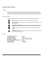
Symbols of display
Special symbols will be shown on the right side of the display depending on the function:
SHIFTLOCK. This function will be ON or OFF by pressing the shift key,.
TRANSACTION. This sign shows up, when the Hand Terminal is communicating
with the HOST.
TRANSACTION FAILURE. This sign shows up, when transaction between the
Hand Terminal and the HOST has failed. This will also be indicated by five beeps.
LASER. This sign shows up, when the laser reader is activated. (yellow laser
button)
EXTERNAL READER. This sign shows up, when the external reader is activated.
(SHIFTLOCK + laser button )
Sounds
Resetting Hand terminal
Transaction failure
Bad battery condition
Reception of message
Successful reading of laser scanner
Opening keylock
Wrong password
Copyright © 2002 by Nordic ID. All rights reserved.
2 beeps.
5 beeps
3 beeps with different levels
At least 1 beep, can be more.
1 beep
1 long beep
3 fast beeps
4
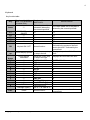
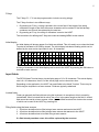
Keyboard
Key function table:
Key
Function with shift key
(shift + key pressed at
the same time ).
Laser
***
F1
F2
F3
F4
F5
RECEIVER mode
ON/OFF
***
***
***
***
OK
Keylock ON / OFF
Arrow
up
Arrow
down
Shift
7
8
9
4
5
6
1
2
3
.
0
DEL
Scrolls display upward
Scrolls display
downward
***
***
***
***
***
***
***
***
***
***
***
MENU
Backlight (option)
Reset
Function with
SHIFTLOCK
Normal function
External reader will be
activated if allowed by
the current input field.
The Laser reader will be activated if
allowed by the current input field.
F6
F1
F7
F8
F9
F10
F2
F3
F4
F5
The cursor will be moved to the next
field and/or the content of the field
sent to the HOST if allowed by the
current field
Displays the previous field of the
form.
Normal function
Moves the cursor step
by step to the left.
Moves the cursor step
by step to the right.
SHIFTLOCK OFF
ABC abc
DEF def
GHI ghi
JKL jkl
MNO mno
PQR pqr
STU stu
VWX vwx
YZÅÄÖ yzåäö
↵ :;!?"#&@|
<>[]Ü{}()ü
Spc + * / % = $ £ ± ½
Normal function
Copyright © 2002 by Nordic ID. All rights reserved.
Displays the next field of the form.
SHIFTLOCK ON
7
8
9
4
5
6
1
2
3
.
0
Removes a character from the
current field.
5
F-Keys
The F-Keys F1 - F10 can be programmed to include recurring strings.
The F-Keys function in two different ways:
1. By pressing an F-Key, a string is printed in the current field. If the length of the string
exceeds the length of the field, the excess characters will be omitted. If the field already
contains a text, this will be replaced by the new text.
2. By pressing an F-key, the string of characters is sent to the HOST.
The instructions for defining the F-Keys are under the heading MENU in this manual.
Initial display
An initial display will always appear if no fields are defined. This will usually occur when the Hand
Terminal is activated or its RAM is cleared. The initial display includes a heading which can be
defined by the user and an input field of max. 18 characters.
0 < H E A D I N G >
1
2
_ _ _ _ _ _ _ _ _ _ _ _ _ _ _ _ _ _
3
A string of characters in the initial display can be sent to the HOST by pressing the OK button or
read with a laser scanner.
Input fields
The RF500 Hand Terminal has a virtual display page of 12 x 20 characters. The actual display
size is 8 x 20 characters, thus 2/3 of the virtual page can be viewed at a time
Depending on the application, the HOST can send fields to the Hand Terminal. Those may be
filled using the keyboard or a laser scanner. Fields are typically underlined.
Locked fields
Fields can generally be filled with text using the keyboard. An exception to this is caused by
locked fields. When a locked field is active, the cursor is the same length as the field. A locked
field cannot be read by a laser scanner, either. A locked field functions like a button the content
of which can be sent to the HOST by pressing OK.
Filling fields using the laser scanner
1. A field can be defined to be filled using a laser scanner and sent to the HOST.
2. A field can be defined to be filled using a laser scanner but not sent to the HOST.
3. A field can be defined not to be filled using a laser scanner.
If a field already contains a text, this will be replaced by the new text.
Copyright © 2002 by Nordic ID. All rights reserved.
6
Writing text in a field
An active field is indicated by the cursor. An active field can be filled with text using the keyboard
and/or using a laser scanner.
You can move the cursor in the field step by step using the arrow keys if SHIFLOCK is ON.
Writing letters
Letters can be written in a field when the SHIFTLOCK is ON by pressing the number keys
containing letters. When a key is pressed once the first indicated letter will appear. When
pressed twice the second letter will be shown, and so on.
CAPITAL- or small letters can be changed by pressing a key for at least 1.2 sec.
Removing letters
Letters can be removed from a field with the DEL key.
An entire field can be cleared by pressing the DEL key for at least 0.5 sec.
Moving between fields
You can move between the fields using the arrowkeys.
By pressing the OK key, you can move to the next field.
MENU
The settings of the Hand Terminal can be changed through the Menu. The Menu will be activated
only if the initial display is on by pressing the keys SHIFT + 0.
You can move in the Menu using the arrow keys. The desired item is selected by pressing the
OK key. You can move backwards in the Menu by pressing << .
After choosing an item in the Menu, it must be confirmed by pressing the OK key. A changed
setting will be signalled by a beep.
Settings
The most important settings can be changed using a password ( 0-9999 ).
The Initial setting is 0.
.
Heading
Extra-ID
Password
F-keys
The Initial display heading. Max 20 characters.
The Hand Terminal sends this ID to the HOST (0-255).
Change of Password ( 0 – 9999 ).
Editing of Function keys F1 - F10. You can define a 15- character- long text under
an F-key. F-Keys can be defined two different ways: To be printed in the field or to
be sent to the HOST. If you add ↵ at the end of a text, it will be sent to the HOST
by pressing the F-key.
Example
F1: Hello ↵ _ _ _ _ _ _ _ _ _ _ Send ”Hello” to the HOST .
F2: Hey _ _ _ _ _ _ _ _ _ _ _ _ Print ”Hey” in the field.
The ↵ character can easily be obtained by pressing SHIFLOCK + . if the capitals
are on.
Copyright © 2002 by Nordic ID. All rights reserved.
7
RF-settings
Channels. Channel 1-7.
Resending times. How many times a message is sent to the HOST if no answer
is receive. If the Hand Terminal cannot get a response from the Base Station, and
all the resending times have been used, the transaction failure sign F will be
prompt on the display.
Reception timelimit. The time limit during which the Base Station must respond
to the Hand Terminal before the message is resent.
Adjustments
Key sounds
Volume
Battery
On / Off
Beep level. Three different levels.
0, if using NI-CD or NI-MH rechargeable batteries. 1, if using normal
batteries.
Info
Information about battery condition and number of software version.
Laserscanner
Do not stare into beam. Danger to the eyes. Class 2 laser product.
Copyright © 2002 by Nordic ID. All rights reserved.
8
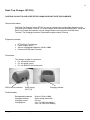
Desk Top Charger (DTC05)
CAUTION ! DO NOT PLACE A DEFECTIVE HAND HELD UNIT INTO THE CHARGER.
General information
The Desk Top Charger (model DTC05) is used for charging the rechargeable batteries of the
PiccoLink RF600 Hand Terminal. It is a fast charger which reduces the charging time. Using the
Desk Top Charger the batteries may be charged without removing them from the Hand
Terminal. The charging procedure is directed through the Hand Terminal.
Equipment needed
•
•
•
•
DTC05 Desk Top Charger
Power Supply (9525)
AA-size rechargeable batteries. NiCd or NiMH
PiccoLink RF600 Hand Terminal
Connectors
The charger includes 3 connectors:
• For the Hand Terminal
• For the power supply
• For the RS232C serial connector
RS232 serial connector
Power supply
(DC 7,5V)
Charging indicator
Technical data
Rechargeable batteries
Charging methods
Charging current
Charging time
Size AA. NiCd or NiMH
Quick charge and trickle
650 mA
Ca 1,5 h (850 mAh battery)
Ca 2,5 h (1400 mAh battery)
Copyright © 2002 by Nordic ID. All rights reserved.
9
Charging the batteries
Caution! Do not attempt to charge regular or alkaline batteries as this may cause an explosion.
Use only rechargeable batteries recommended by the manufacturer.
Charging batteries using the DTC05 Desk Top Charger:
•
•
•
•
•
•
•
Batteries must be in the Hang Terminal to allow charging.
Check that the Hand Terminal batteries are rechargeable.
Check that the settings for the Hand Terminal have been configured as follows:
MENU > ADJUSTMENTS > BATTERY > 0. (See User´s Manual: MENU).
Connect the adapter (9525) to the power supply connector of the charger (see picture).
Place the Hand Terminal in the charger.
The charging indicator led will remain ON during quick charging.
The led will to blink when the battery is fully charged. Charger current led will then be
reduced to a trickle charge current
The Desk Top Charger may only be used with the Power Supply provided by the manufacturer.
The Hand Terminal cannot be used during battery charging.
It is normal for the base of the charger to become warm during charging.
Audio signals and the led indicator on the charger
Charging indicator:
Quick charge
Trickle charge
The led remains on
The red led blinks
Audio signals:
Three successive beeps
Two successive beeps (long-short)
Charging not allowed (the Hand Held unit does not
include rechargeable batteries).
The battery is being charged
TO AVOID DAMAGE OR ACCIDENTS, THE DESK TOP CHARGER MUST NOT BE USED FOR ANY
OTHER PURPOSE THAN THAT STATED IN THIS MANUAL.
Copyright © 2002 by Nordic ID. All rights reserved.