1
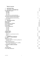
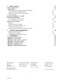
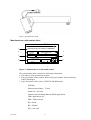
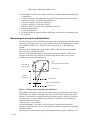
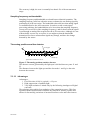
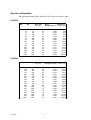
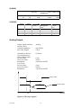
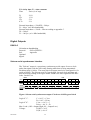
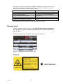
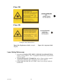
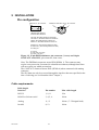
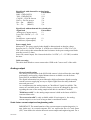
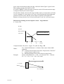
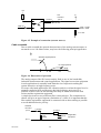
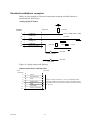
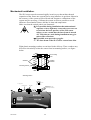
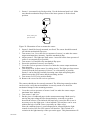
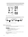
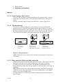
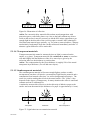
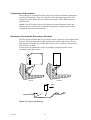
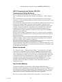
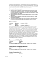
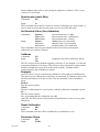
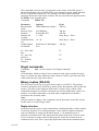
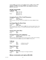
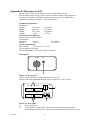
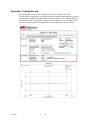
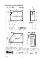
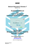
User’s Manual
SLS 5000
SLS 6000
SLS 2401
SLS 2008
Table of contents
1
INTRODUCTION
3
2 TECHNICAL DESCRIPTION
Identification of parts
SLS5000
SLS 6000
SLS 2401
SLS 2008
Manufacturers serial number label
Measurement principle and definitions
Sampling frequency and bandwidth.
The analog position sensitive detector
Linearization
4
4
4
4
5
5
6
7
8
8
9
3 TECHNICAL DATA
Block diagram
Dimensions
Environmental conditions
Power requirements
Performance
Sensor configuration
SLS5000
SLS6000
SLS2401
SLS2008
Analog Output
Digital Outputs
RS232-C
Selcom serial synchronous interface
RS422
Invalid output
9
9
10
10
10
10
11
11
11
12
12
12
13
13
13
14
14
4 SAFETY REQUIREMENT
Symbols
Safety precautions
Summary of user precautions regarding laser
Emission delay
Safety of Laser products.
Maximum Permissible Exposures (MPEs)
Laser product classification.
Calculation of MPE and NOHD
MPE
NOHD
Warning labels
Laser Safety References
03-09-05
1
15
15
15
16
16
17
17
17
18
18
18
19
20
5 INSTALLATION
Cable requirements
Analog output
Scale factor current output and engineering units
Load conditions for analog output.
Alternative connections for valid output
Cable crosstalk.
Electrical installations, examples
Mechanical installation.
For a single SLS sensor system
For a dual SLS sensor system
Hints for measurements
Material
Unstable thickness reading
Surface texture. Static texture error
Temperature of the material
Geometry of the material. Secondary reflections
6
SERVICE AND MAINTENANCE
Keeping the front glass clean
Visual check for damage
LED-indicators (Yellow and Green)
21
21
22
22
25
25
26
27
29
30
30
32
33
35
35
37
37
38
38
38
39
7 APPENDIXES
Appendix A, Revision page
Appendix B, Accessories
Appendix C, SLS-asynch-1, protocol
Appendix D, SLS power unit 24
Appendix E, Connection table
Appendix F, Quality Record
Appendix G, Dimensional drawings
LMI Technologies AB
Ögärdesvägen 19 A
Box 250,
S-43325 Partille
SWEDEN
Tel: +46 (0)31 336 25 10
Main +46 (0)31 336 25 00
Fax: +46 (0)31 44 61 79
Internet: http://www.lmint.com
03-09-05
LMI Technologies (USA), Inc.
21455 Melrose Ave. Suite 22
SOUTHFIELD MI 48075
USA
Tel: +1 248 355 5900
Fax: +1 248 355 3283
40
40
40
40
51
53
54
57
LMI Technologies BV
Valkenburgweg 223
6419 AT Heerlen
The Netherlands
Tel: +31 45 850 7000
Fax: ++31 45 574 2500
LMI Technologies Inc.
205-7088 Ventura Street
Delta, BC, V4G-1H5
Canada
Tel: +1 604-940 0141
Fax: +1 604-940 0793
Printed in The Netherlands
2
1 INTRODUCTION
This manual is a description of the Selcom Laser Sensor (SLS) family. The
sensors have laser classification 2, 3R or 3B. Read chapter Laser Safety
precautions before connecting the sensor.
This sensor is intended for use in applications where distance, thickness or level is
to be measured. The ambient temperature surrounding the sensor should be 0°C to
50°C but the temperature of the measured object may vary from deep frozen to
+1600°C. The sensor is equipped with a temperature guard that shuts the laser off
should the surrounding temperature exceed the limits.
No changes or modifications may be made to the sensor or its cable unless you
have a written permission from LMI Technologies. If the sensor is opened or
modified without permission, warranty is voided.
Caution- Use of controls or adjustments or performance of
procedures other than those specified herein may result in
hazardous radiation exposure.
For your own safety, follow the instructions in this manual.
If you get problems when using the SLS sensor, contact your local LMI
Technologies office or your local distributor.
The delivery of a SLS 5000 contains:
•
•
•
SLS 5000 sensor
Isolation washers 8 pcs
Users manual 1 pcs
The delivery of a SLS 6000 contains:
•
•
•
SLS 6000 sensor
Isolation washers 4 pcs
Users manual 1 pcs
The delivery of a SLS 2401 contains:
•
•
•
SLS 2401 sensor head and SLS Controller
Isolation washers 4 pcs
Users manual 1 pcs
The delivery of a SLS 2008 contains:
•
•
•
03-09-05
SLS 2008 sensor head and SLS Controller
Isolation washers
Users manual 1 pcs
3
2 TECHNICAL DESCRIPTION
Identification of parts
SLS5000
Emission indicator device
1, Illuminated when power is ON
2, Green when target is within the
measurment range
3, Yellow when no target is present
within the measurment range
Manufacturers serial
number label
Laser shutter
SELCOM
SLS5000
Laser emitting
lable
Laser aperture
Receiver aperture
Front glass
Mounting holes
Side view
Front view
Figure 1: Identification of parts SLS 5000
SLS 6000
Laser emitting
label
Air purge inlet
Mounting Holes
M8 (4X), top mount
DANGER
Laser
Class 3B
Selcom
LASER MEASUREMENTS
SLS 6000
Emission indicator:
1.Illuminated when power is on
2. GREEN when target is within
the measurement range.
3. YELLOW when no target is present
within the measurement range.
Laser aperture, incl laser shutter
Receiver Aperture
Figure 2:SLS 6000
03-09-05
4
Manufactures serial
number label
SLS 2401
Emission indicator on 2401 head is RED when laser is ON. Function of Emission
Indicator on SLS controller see previous page
Figure 3. SLS 2401. SLS controller top and 2401 head bottom.
SLS 2008
Emission indicator on SLS2008 sensor head is RED when laser is ON.
Figure 4. SLS controller
03-09-05
5
Figure 5. SLS2008 sensor head
Manufacturers serial number label
Selcom
1
2
BOX 250 S-433 25 PARTILLE SWEDEN
810555
SLS2070/200-WO
PART NO
4
345
SN
6
3
TYPE
5
0-20 mA
OUTPUT
MANUFACTURED:
NOVEMBER
MONTH
8
1996
YEAR
7
Figure 3: Manufacturers serial number label
The serial number label contains the following information:
1. The address of the production location.
2. The part number of the product. Refer to this part number when contacting
LMI Technologies.
3. Type description of the sensor. SLS5070/200-BM means:
SLS5000
Measurement Range = 70 mm
Stand Off = 200 mm
Optimized for Building Material (BM) applications
Other applications are:
MM = Molten metal
RO = Road
RU = Rubber
SW = Saw mill
03-09-05
6
Other letter combinations may occur.
4 Serial number of the sensor. Refer to this serial number when contacting LMI
Technologies.
5 Available outputs, one analog and one digital. The outputs are selected when
ordering the sensor. Possible combinations are:
0-20 mA / Selcom or 4-20 mA / Selcom
0-20 mA / RS422 or 4-20 mA / RS422
RS232 is always available, ref to appendix for details.
6 Month of manufacture.
7 Year of manufacturer
8 CE-mark. Indicates that the product fulfills the emc-directive according to EN
89/336/EEC
Measurement principle and definitions
The SLS sensors consist of a light source and a detector integrated with optics and
electronics. The light source is a semi conductor laser diode operating in a pulsed
mode with 50% duty cycle. The pulse rate or frequency is 16 000 times per
second.
This laser diode illuminates a spot on the surface of the object to be measured,
(log, car body, gypsum board etc.).
The spot is not only detectable to the human eye but also clearly visible to the
detector of the SLS. The detector is situated at the back of the receiver part,
similar to the retina of the human eye.
PSD
(Position Sensitive photo Detector)
Semiconductor
laser and optics
Receiver optics
Stand Off
Distance, SO
Close End, CE
Measurement Range, MR
Far End, FE
Figure 4: Measurement principle and definitions
Depending of the distance between the SLS sensor and the light spot, the Stand
Off distance, the image of the light spot will be focused on a certain spot on the
detector. The detector is a high resolution, position sensitive detector. It converts
the light spot to electrical signals from which the electronics can calculate the
actual distance to the object.
”Moving objects, no problem”
The measurement is very rapid. The SLS sensor repeats the measurement
sequence 16000 times per second. This makes it possible to measure moving and
vibrating objects.
By using several SLS sensors you can measure thickness, profiles, diameter, etc.
03-09-05
7
The accuracy is high; the error is normally less than 0.2% of the measurement
range.
Sampling frequency and bandwidth.
Sampling frequency and bandwidth are related but not identical quantities. The
sampling frequency tells how often the sensor evaluates the raw analog signal by
performing an A/D conversion. The bandwidth value tells how that analog signal
is conditioned before the A/D conversion. In order to avoid certain signal
processing problems, the bandwidth has to be lower than the sampling frequency
(it may not exceed 50% of the sampling frequency), and for that reason the signal
is put through an analog filter stage before the A/D conversion. Although it is not
a theoretically correct way to express it, one might say that the bandwidth
determines how fast a measurement signal may change, and have the change
detected by the sensor.
The analog position sensitive detector
Incoming light
I1
I2
1
2
0
X
Light spot
Typical size of the detector is 1*10 mm
Figure 5: The analog position sensitive detector
The detector current, generated by the light spot is divided into two parts: I1 and
I2.
The distances between the light spot and the electrodes 1 and 2 give the ratio
between the currents.
2.1.1.1 Advantages
Advantages:
1 Fast. Rise time 10-90 % (typical) = 0.2 µsec.
2 High suppression of ambient light.
3 Very high resolution. Limited only by the following Analogue-to-Digital
converter.
The technique also enables fast regulation of the output laser power. This fast
regulation makes measurement of almost any material or surface possible and
allows for fast and big variations of measured surfaces color and reflectiveness.
03-09-05
8
Linearization
SELCOM
Detector output
SLS5000
Non-linearized
function
Desired
function
A small portion of
the scattered light
Scattered
light reflection
The function between the raw output from the detector and the actual distance
between the SLS sensor and the measured object is non-linear. This non-linearity
is mainly due to the geometry of this type of measurements and to the analog
portion of the data processing. Therefore each sensor is factory calibrated to
compensate for any non-linearity or other built-in error. Using a moving target
and a reference scale a translation table is constructed and stored in non-volatile
memory inside the sensor.
Figure 6: Illustration of linearization
3 Technical data
Block diagram
Principal diagram:
Laser
driver
Control
logic
x1+x2
x1
Laser
diode
Preamplifier
A/D-conv.
DSP
x1-x2
x2
Internal data bus
PSD
Host processor
Power
regulator
+ 24 VDC
Figure 7: Principal diagram
03-09-05
9
Interface
Dimensions
SLS5000
Length:
Height:
Width:
Weight:
SLS6000
Length:
Height:
Width:
Weight:
135 mm
105 mm
51 mm
1.1 kg
(5.3 inches)
(4.1 inches)
(2.0 inches)
(2.2 lbs)
376 mm
169 mm
70 mm
4.4 kg
(14.8 inches)
(6.6 inches)
(2.7 inches)
(9.9 lbs)
Environmental conditions
Temperature:
Operating: 0-50 °C (32-120 °F)
Storage: -30-70 °C (-20-160 °F)
Protection class :IP65
(NEMA 4)
(Excluding connector)
Power requirements
Input voltage :+24 VDC (18-32 VDC)
Input current: 250 mA at 24 V (350-200 mA for 18 -32 V)
Start-up current: typical 1,1 A for 8 ms
Performance
Resolution
0.025 % of Measurement Range
Inaccuracy
0.2 % of Measurement Range (Includes non-linearity and error)
Sampling rate
16 kHz
Bandwidth
Up to 2 kHz depending on configuration settings
03-09-05
10
Sensor configuration
Measurement Range (MR), Stand Off (SO), Beam divergence angle
SLS5000
MR (mm) SO (mm) Spot size at
SO (mm)
6
20
10
20
35
35
70
100
70
150
200
325
400
750
1000
50
50
100
100
100
200
200
200
300
300
300
400
450
600
1250
Beam
Resolution
(rad)
1 LSB= (um)
divergence
0,1
0,1
0,1
0,1
0,1
0,3
0,3
0,3
0,3
0,3
0,3
0,5
0,6
0,8
1,0
0,060
0,060
0,030
0,030
0,030
0,025
0,025
0,025
0,017
0,017
0,017
0,013
0,011
0,008
0,004
1,50
5,00
2,50
5,00
8,75
8,75
17,50
25,00
17,50
37,50
50,00
81,25
100,00
187,50
250,00
SLS6000
MR (mm) SO (mm) Spot size at
SO (mm)
50
362
100
175
250
362
510
180
225
375
525
375
575
725
300
550
850
1000
03-09-05
400
480
500
500
500
500
600
738
750
750
750
1000
1000
1000
1250
1250
1250
1250
Beam
Resolution
divergence (rad) 1 LSB= (um)
0,5
0,6
0,6
0,6
0,6
0,6
0,7
0,7
0,7
0,7
0,8
1,0
1,0
1,0
1,2
1,2
1,2
1,2
0,013
0,010
0,010
0,010
0,010
0,010
0,008
0,007
0,007
0,007
0,007
0,005
0,005
0,005
0,004
0,004
0,004
0,004
11
12,50
90,50
25,00
43,75
62,50
90,50
127,50
45,00
56,25
93,75
131,25
93,75
143,75
181,25
75,00
137,50
212,50
250,00
SLS2401
MR (mm) SO (mm) Spot size at
SO (mm)
20
50
50
80
Beam
Resolution
divergence (rad) 1 LSB= (um)
0,06
0,09
0,060
0,038
5,00
12,50
SLS2008
MR (mm) SO (mm) Spot size at Beam
Resolution
SO (mm)
1 LSB=
divergence
(rad)
(um)
325
1350
2,0
0,004
81,25
325
1600
2,0
0,003
81,25
325
1800
2,0
0,003
81,25
325
2010
2,0
0,002
81,25
Analog Output
Output signal interface:
current source
external impedance:
max cable length:
selectable at delivery
(see manufacturers
serial number label):
Far end value:
Close end value:
Resolution:
or 4-20 mA
Far end value:
Close end value:
Resolution:
Analog
max 500 Ω
100 m
0-20 mA
0 mA
20 mA
4.88 microA/LSB
4 mA
20 mA
3.90 microA/LSB
Step function
Tc
Td
time [ms]
Figure 8: The step response
03-09-05
Analog output
12
Td = delay time, Tc = time constant
Time
Error (% of step)
Tc
2Tc
3Tc
4 Tc
36 %
13 %
5%
2%
External impedance = 500 ΩTd = 200 µs.
Tc = 80 µs. (at 2 kHz bandwidth)
External impedance = 500 Ω + filter according to appendix C.
Td = 300 µs.
Tc = 100 µs. (at 1.6 kHz bandwidth)
Digital Outputs
RS232-C
No hardware handshaking
Protocol:
SLS-ASYNCH-1
Ref:
Appendix
Optional
digital:
Selcom serial synchronous interface
The ”Selcom” output is a proprietary synchronous serial output. It uses a clock
and a data signal; with the clock only running while data is being transmitted.
Each data item is 16 bits . The same physical output can also be configured in for
serial as RS422. The Selcom serial is a gated clock /inverted clock and data and
data inverted according to the figure below. MSB is the most significant bit and C
is the “Invalid” bit.
Data
MSB
11 10
9
8
7
6
5
4
3
2
1
LSB
0
C
C
Data
Clock
Clock
Figure: Selcom serial synchronous output. Clock rate 16 kHz, gated clock
Logical ”1”:
C > 0.6 V + C-inv.
D > 0.6 V + D-inv.
Logical ”0”:
C-inv. > 0.6 V + C
D-inv. > 0.6 V + D
Max. Load : (OH = Output High, OL = Output Low)
Voltage:
U(OH) > 2.0 V
U(OL) < 0.8 V
03-09-05
13
C
Current:
I(OH) > 40 mA
I(OL) < -40 mA
or
RS422
Full duplex
Protocol:
Ref:
SLS-ASYNCH-1
Appendix E
Invalid output
100 ohm
Inv.out +
Inv.out -
Figure 9: Optocoupled
Max ratings: VCE 35 V
IC 50 mA
Rise time
60 µs
(typical):
Fall time
53 µs
(typical):
03-09-05
14
4 SAFETY REQUIREMENT
Symbols
The following symbol appears in the manual:
The symbol identifies conditions or practices that are hazardous
Safety precautions
The light source of the SLS is a semiconductor laser emitting visible or invisible
light. The SLS has a 2, 3R or 3B classification according to IEC 60825-1 Safety
of Laser products and complies also with FDA performance standards for
laser products except for deviations pursuant to Laser Notice No. 50, dated
July 26, 2001.
The classification for each sensor is stated on the laser warning labels on the
sensor. Make sure that you take the proper precautions for the laser class of the
sensor you are using. If you are uncertain of the laser class or if you have
questions regarding precautions or laser safety standards, please contact your
nearest LMI office. The following safety precautions must be observed when
working with the equipment:
The emitted light can damage the eye if directly exposed, or if the
laser light is reflected by a mirror or any mirror like surface
directly into the eye.
Follow all warnings and instructions in the manual. Personnel working with or
near the SLS must be informed about safety distance, hazardous area and other
installation specific hazards.
Caution- Use of controls or adjustments or performance of
procedures other than those specified herein may result in
hazardous radiation exposure.
Ensure that the voltage from the power supply matches the specifications for the
equipment.
If otherwise is not explicitly stated, always disconnect the power supply unit
during installation, service and maintenance of the SLS. The power supply unit
delivered from LMI Technologies is provided with a key control. Remove this
key to prevent that the laser is turned on unintentionally.
If possible seal off the hazardous area defined in the Safety distance/ NOHD
section to prevent unauthorized personnel from getting exposed to laser light.
It is always recommended to follow as many of the precautions as possible
irrespective of laser class.
03-09-05
15
Summary of user precautions regarding laser
For products with a laser safety class 2, 3R or 3B (See text of IEC 60825-1 for
complete precautions, subclause indicated in table):
Requirements
subclause
Class
3B 3R 2
Laser safety
Officer, 10.1
Remote
interlock, 10.2
Key control
10.3
X
For 3R --required only if non visible radiation
X
Beam
attenuator
(Laser shutter)
10.4
Emission
indicator device
X
Connect to room or door circuits. Pin no 14 (LASER ON) of
the SLS connector can be used for this purpose.
Remove key when not in use.
Key control is provided when power supply is delivered by
LMI Technologies. To conform to safety requirements a key
control must be installed. Use pin no 15 (+24 VDC) of the
SLS connector to /connect/disconnect the power of the SLS.
When in use prevents inadvertent exposure.
Provided by LMI Technologies and permanently mounted
on the front of the sensor. See chapter 2, figure 1.
Warning signs,
10.5
Beam path,
10.6
Specular
reflection, 10.7
Eye protection,
10.8
Protective
clothing, 10.9
Training, 10.10
X
X
X
(X)
Indicates that the laser is energized. Required for 3R only if
nonvisible laser.
See chapter 2, figure 1.
Provided by LMI Technologies and permanently mounted
on the side of the sensor. One of the LEDs is always lit.
• The yellow LED is lit when the sensor signals Invalid,
e.g. no object inside the measurement range, too little
light scattered back to the detector, to much light
scattered back to the detector.
• The green LED is lit when the measurement is Valid
Follow precautions on warning signs.
X
X
Terminate beam at the end of its useful length.
X
X
Prevent unintentional reflections
X
Required if engineering and administrative procedures not
practicable and MPE exceeded.
Not required
X
X
X
Required for all operator and maintenance personnel.
Emission delay
LMI Technology’s sensors can be equipped with two different types of emission
delay. One (called Laser ON delay) will always cause a short delay every time
the laser control signal is turned on, before the laser actually starts emitting laser
light. The other type (called Power ON delay) will only cause a delay when the
sensor is first powered up. All subsequent cycling of the laser control signal will
control the laser without any delays. See quality record.
03-09-05
16
Safety of Laser products.
Maximum Permissible Exposures (MPEs)
IEC 60825-1, Safety of laser products, relies on the concept of the MPEs. The
MPEs are derived primarily from animal and human data, but take into account of
human variability and laser parameters Clause 3.55 of IEC 60825-1 defines the
maximum permissible exposures as “The level of laser radiation to which, under
normal circumstances, persons may be exposed without suffering adverse effects.
The MPE levels represent the maximum level to which the eye or skin can be
exposed without consequential injury immediately after, or after a long time, and
are related to the wavelength of the radiation, the pulse duration or exposure time.
The tissue at risk and, for visible and near infrared radiation, the size of the retinal
image. For calculation of MPE see “Calculation of MPE and NOHD in this
manual.
Laser product classification.
The classification of a laser product is based on the radiation emitted during the
normal operation and any reasonable foreseeable fault condition for that product.
4.1.1.1 Class 2 laser products:
Class 2 laser products would not cause permanent damage to the eye under
reasonable foreseeable conditions of operation, provided that any exposure can be
terminated by the blink reflex (assumed to take 0,25 s). Because classification
assumes the blink reflex, the wavelength must be in the visible range (400 nm to
700 nm). The Maximum Permissible Exposure (MPE) for visible radiation for
0,25 s is 25 W per square meter, which is equivalent to 1 mW entering an aperture
of 7 mm diameter (the assumed size of the pupil).
4.1.1.2 Class 3R laser products
Class 3R laser products emits radiation where direct intrabeam viewing is
potentially hazardous but the risk is lower than for Class 3B lasers, and fewer
manufacturing requirements and control measures for users apply than for Class
3B lasers.
4.1.1.3 Class 3B laser products
Class 3B laser products are unsafe for eye exposure. Usually only ocular
protection would be required. Diffuse reflections are safe if viewed for less than
10 s.
4.1.1.4 Nominal Ocular Hazard Distance (NOHD) or safety distance.
The NOHD is related to the Maximum Permissible Exposure (MPE). The NOHD
is the nominal distance at which the exposure equals the MPE. The concept of
NOHD is used when laser products such as range finders or display lasers are to
be used in the open air.
03-09-05
17
S ta n d O ff
SO
Irra d ia n c e o r R a d ia n t E x p o s u re e q u a ls M P E
B e a m d iv e r g e n c e
S L S L aser
A p e rtu r e
NOHD
E x p o s u re d o e s
N ot exceed M PE
E x p o s u re e x c e e d s M P E
The NOHD is depending on Stand Off and working power and can be found in
the Quality record that comes with each sensor delivered. See appendix GQuality Record for the actual NOHDof your sensor and actual parameters for
your SLS in order to calculate MPE and NOHD.
Figure 10: The concept of nominal ocular hazard distance
Calculation of MPE and NOHD
MPE
See section 13 in the IEC80825-1. Parameters necessary to be able to calculate the
MPE are exposure time base, max pulse power, wavelength, pulse repetition
frequency and pulse duration. These parameters can be found as follows.
Parameter
Exposure time base
Max pulse power, wavelength and pulse
duration
Pulse repetition frequency
Time base for MPE is 10 s for invisible
(see example A.4-2 in the IEC 60825-1 ed.
1.2) and for Visible 0,25 s (example A.41).
Explanatory label affixed to the product
Same as the term “Sampling frequency”
found in the Q-record.
16000 Hz for all SLS
4.1.1.5 MPE values for SLS.
The MPE values as well as the results of the calculation of each of three
requirements of 13.3 in IEC 80625 are stated in the table.
Wavelength
13.3 a
J/m2
13.3.b
J/m2
13.3.c
J/m2
Most
restrictive
J/m2
655 nm (visible)
780 nm (NIR)
7,52E-03
1,09E-02
1,59E-03
9,14E-04
9,46E-04
5,44E-04
9,46E-04
5,44E-04
Most
restrictive
corresponds
to MPE
W/m2
30,3
17,4
NOHD
See Annex A, section A.5 in the IEC standard and TR 60825-10. Parameters
03-09-05
18
necessary to be able to calculate the NOHD are MPE, max average power, beam
divergence, diameter of emergent laser beam (a) and Non Gaussian correction
factor. These parameters can be found as follows.
Parameter
Max average power
Beam divergence angle
Non Gaussian correction factor
MPE
Q-record
See section “ Sensor configuration”
LMI use 2.5.
See table above
Diameter of emergent laser beam (a)
5 mm
The NOHD value for each sensor can be found in the Q-record.
Warning labels
Products complies with IEC 60825-1 and with FDA performance standards for
laser products except for deviations pursuant to Laser Notice No. 50, dated
July 26, 2001.
The following labels are attached to the sensor:-All languages:
Figure 11: Manufacturers serial number label
Class 2
03-09-05
19
Class 3R
Class 3B
Example -Near Infrared laser
Figure 10a: Explanatory label, (example
English)
Figure 10 b: Aperture label
Laser Safety References
1 International Standard IEC 60825-1 (2001-08) Consolidated Edition,
Safety of laser products - Part 1: Equipment classification, requirements
and user's guide
2 Technical Report IEC TR 60825-10, safety of laser products- part10.
Application guidelines and explanatory notes to IEC 60825-1
3 Laser Notice No. 50, FDA and CDRH http://www.fda.gov/cdrh/radhealth.html
03-09-05
20
5 INSTALLATION
Pin configuration
DSUB-15 pin, pin connector
1
.....
.....
.....
CONTACT series R2.5-16 pin, pin connector
12
11
1
15
16
1 Receive data, RS232-C
9 Transmit data, RS232-C
3 CLOCK, SELCOM interface or RS422 Rx+
4 CLOCK-inv, SELCOM interface or RS422 Rx5 DATA, SELCOM interface or RS422 Tx+
6 DATA-inv, SELCOM interface or RS422 Tx8 Invalid out-, (when analog interface is used)
12 Invalid out+, (when analog interface is used)
13 Analog out
11 Ground
14 Laser ON, (+24 VDC)
15 Power, (+24 VDC)
Figure 12: 15 pin DSUB miniature, pin connector (3 rows) and 16 pin
CONTACT series R2.5, pin connector, front views.
Note: The DSUBmin connector meets IP50 (NEMA 1). The connector may
require extra protection if mounted in a humid environment, although dust alone
will not require any added precautions.
The CONTACT connector meets IP65 (NEMA 4) when connected with mating
connector.
The SLS data can only be accessed through the interface that was specified at the
time of ordering (see serial number label ”Output”).
Cable requirements
Cable length
Interface
Pin number
Max cable length
RS 232
1, 9, 11
15m
RS 422 or Selcom serial
3, 4, 5, 6
100 m
Analog
11, 13
100 m (<7.5 Ω/signal lead)
Invalid
8, 12
100 m
03-09-05
21
Signal leads with demand for twisted pairs
Interface
Pin number
RxD - GND (RS232)
1, 11
TxD - GND (RS232)
9, 11
CLOCK - CLOCK-inverse
3, 4
DATA - DATA-inverse
5, 6
Rx+ - Rx(RS422)
3, 4
Tx+ - Tx(RS422)
5, 6
Signal leads without demand for twisted pairs
Signal lead
Pin number
Analog out (Current source)
13
Laser ON +24VDC (+5 - +32
14
VDC)
Invalid out+ (optocoupled)
12
Invalid out- (optocoupled)
8
Power supply leads
Main power. The power supply leads should be dimensioned so that the voltage
between pin 15 (+24VDC) and pin 11 (GND) never falls below 18 VDC. For a 24
VDC power source this means that the total resistance in the power and ground leads
must not exceed 15 ohms.
Laser ON (control input). Pin 14 must be held at +24 VDC (+5 - +32 VDC) to enable
the laser.
Cable screening
The cable shall include a screen connected to GND at the ”sensor end” of the cable.
Analog output
General considerations
The analog current output of the SLS5/6000 sensors is derived from the same high
performance and accuracy digital distance data as available over the Selcom
Serial, RS232 and RS422 interfaces.
The digital information has passed through a high performance digital to analog
current converter supplying an easy to acquire signal form for many industrial
users and processes.
As a complement to the analog output, an ”Invalid out” signal is available. The
sensors are available in two versions (factory set, not to be changed by the user!)
regarding the state of the analog output when data is considered ”invalid”:
”Hold latest valid” i.e. the analog output current is held at the latest valid D/A
converted data value.
”Zero out on invalid” is only available with 4-20 mA output i.e. the analog
current output is set to 0 mA as long as data is considered invalid.
Scale factor current output and engineering units
IMPORTANT: The transformation of the current output to engineering units (i.e.
mm, inches etc.) in a control computer, PLC etc. requires the use of a ”scale factor
(SFI )” that defines the relation between current output and engineering unit. For a
03-09-05
22
given sensor measurement range the only valid scale factor figure is given in the
table Analog current scale factor for SLS
It is NOT CORRECT and will lead to erroneous results if the measurement range
is simply divided by the current range!!
If an absolute distance between the target and the sensor (or some other ref. Point)
is to be computed, it is necessary to be aware of the fact that the fixed calibration
point between the sensor and the current output is defined at the Stand-Off
distance as being 10 mA for a 0-20 mA sensor and 12 mA for a 4-20 mA sensor.
Referencing of analog current output to sensor - target distance
4 - 20 mA case
D (mm)
Far End
Stand-off (SO)
SO is ”fixed point” for the
relation between MR and I
Close End
4
12
20
I (mA)
Compute distance D (sensor - target): D = (12 - I) * SFI + SO
Where:
Example:
SO = Stand-Off distance i.e. distance from sensor front to MR
midpoint
SFI = Analog current output scale factor. Expressed as ”mm/mA”.
I = Analog current output in mA.
D = Measured distance from sensor front to target in mm.
Sensor is SLS5200/300 => SFI = 12,8 mm/mA SO = 300 mm
D = (12 - 5,5) * 12,8 + 300 = 383,2 mm
D
D
I = 5,5 mA
SO (=300mm)
03-09-05
23
0 - 20 mA case
D (mm)
Far End
Stand-off
(SO)
Close End
0
10
20
I (mA)
Compute distance D (sensor - target): D = (10 - I) * SFI + SO
Example:
Sensor is SLS5325/400 => SFI = 16,64 mm/mA, SO = 400 mm
D = (10 - 13,5) * 16,64 + 400 = 341,76 mm
D
I = 13,5 mA
SO (=400mm)
Analog current scale factors (SFI) for SLS sensors:
MR (mm)
6
10
16
20
35
50
70
100
150
175
200
225
250
300
325
375
525
550
575
03-09-05
0-20 mA SFI
(mm/mA)
0,3072
0,512
0,8192
1,024
1,792
2,56
3,584
5,12
7,68
8,96
10,24
11,52
12,8
15,36
16,64
19,2
26,88
28,16
29,44
24
4-20 mA SFI
(mm/mA)
0,3840
0.64
1,024
1,28
2,24
3,2
4,48
6,4
9,6
11,2
12,8
14,4
16,0
19,2
20,8
24,0
33,6
35,2
36,8
725
850
1000
37,12
43,52
51,2
46,4
54,4
64,0
Load conditions for analog output.
The current output load resistance should not exceed 500 ohms. A return path to
ground should be provided via pin 11 (GND). The total resistance in the analog
out lead and the ground lead must not exceed 15 ohms.
SLS5000 connector
0-20mA
+
pin 13
max 500 ohm
pin 11
0-10 VDC
-
max 100 meters
max 7.5 ohm /signal lead
Figure 13: Example of connection:
Note: We recommend the use of temperature stable resistors to reduce the effects
of voltage variations due to resistance changes.
Always turn the power off before connecting or disconnecting the analog output
load.
Alternative connections for valid output
The output transistor conducts as long as the measurement is valid.
+ 5V
V+
SLS2000
100 ohm
green
I = max 50 mA
Valid out
yellow
Figure 14: Example of connection (current sink):
03-09-05
25
4.7 k ohm
LOW = Valid
HIGH = Invalid
+ 5V
V+
SLS
connector
100 ohm
pin 12
I = max 50 mA
Valid out
LOW = Invalid
HIGH = Valid
pin 8
4.7 k ohm
Figure 15: Example of connection (current source):
Cable crosstalk.
Due to cable crosstalk the spectral characteristics of the analog current output, as
measured over a 100 Ohm resistor, may have the following principal appearance:
SLS5000 signal spectrum
HF-noise spectrum
1
10
100
kHz
Figure 16: Illustration of spectrum
The analog output of the SLS sensor mainly finds its use in low bandwidth,
industrial measurement and control applications. The signal conversion equipment
in such applications is normally band limited to low frequencies making the
system insensitive or high frequency noise.
For some wide band applications like vibration analysis or when the signal is to be
manually studied with an oscilloscope, the high frequency noise may be a
problem. In these cases an anti-aliasing filter may be added between the load
resistor and the registration equipment.
A simple but in most cases sufficient filter is shown below. The components as
chosen will give an upper frequency limitation of 1.6 kHz. It is important that the
filter and the registration equipment is connected with as short cabling as possible
to avoid additional noise pick-up.
SLS5000
connector
pin 13
I (output)
10 k ohm
Load
resistor
10 nF
pin 11
03-09-05
26
Registration
equipment
Electrical installations, examples
Below are four examples of electrical connections using the available interfaces
provided by the SLS sensor:
Analog output, 0-20 mA
SLS5000
connector
User end
8
Invalid out -
12
Invalid out +
11
GND
13
Analog out
14
Laser ON
15
Power (+24 VDC)
4.7 k ohm
LOW = Invalid, HIGH = Valid
+ 24 VDC
10 k ohm
500 ohm
10 nF
0-10 V
+ 24 VDC
Remote control
+ 24 VDC
Key switch
Figure 18: Analog output with filtering
Selcom synchronous serial interface
SLS
connector
03-09-05
User end
3
Clock
4
Clock-inverse
5
Data
6
Data-inverse
11
GND
14
Laser ON
15
Power (+24 VDC)
Connect to SSP connector J1 or J2, ref to SSP manual.
Connect to OIM-II board connector P2, ref to OIM manual.
If an OIM-I board is used the Key switch must be provided,
ref. fig. 4.4.1.
27
Selcom synchronous serial interfaceRS422 interface
SLS
c o n n e c to r
U ser end
3
R x+
T x+
4
R x-
T x-
5
T x+
6
T x-
R x+
R x-
11
GND
14
Laser O N
15
P o w e r (+ 2 4 V D C )
GND
+ 24 VDC
R e m o te c o n tro l
K e y s w itc h
+ 24 VDC
Figure 19: Selcom synchronous serial interfaceRS422 interface
RS232 interface
SLS
connector
User end
1
Receive data
Transmit data
9
Transmit data
Receive data
11
GND
GND
14
Laser ON
15
Power (+24 VDC)
+ 24 VDC
Remote control
Key switch
03-09-05
28
+ 24 VDC
Mechanical installation.
The SLS sensor must be mounted rigidly in such a way that neither thermal
expansion of the fixture nor external forces may influence its position. Otherwise
the accuracy of the system will be affected and frequent re calibrations of the
system may be necessary. Calibrate the system as often as possible to avoid
influence of mechanical fixture drift due to time and temperature.
Make sure that the optical path is not obstructed.
•1 It is possible during installation that unintentional
exposure to laser light may occur take extra care not
to look into the laser aperture of the SLS sensor
unless you are certain that the laser beam is turned
off. Tools that are used during installation may give
mirror like reflections.
•2 If possible wear protective goggles.
•3 The laser beam of the SLS sensor cannot burn skin.
Eight plastic mounting washers are enclosed in the delivery. These washers may
be used to electrically isolate the sensor from its mounting surface, see figure
below.
M6 mounting
bolts
Isolation
washers
Washers
Mounting surface
Mounting Surface
7,0 mm
Air purge inlet
Mounting plate
DANGER
Laser
Class 3B
03-09-05
Bolt (M8)
Drill diam.
10.5 - 11.0 mm
Isolation washer (4x)
Washer (4x)
Mounting Holes M8(4x)
Selcom
LASER MEASUREMENTS
SLS 6000
29
For a single SLS sensor system
The distance between the SLS sensor and the reference plane must not be
changed.
1
1
2
3
Target
4
Reference
roller
Reference
roller
Figure 20: Measurement against the reference plane
1. Laser beam
2. If the incoming laser beam is not perpendicular to the measured surface,
compensation for the angle may be necessary.
3. Good contact between the reference surface and the measured material is
important.
4. Eccentricity of a reference roll may cause variation in the thickness value.
Keeping track of the roll while performing multiple calibrations may solve
this problem.
SLS5000
SLS5000
SLS5000
SLS5000
For a dual SLS sensor system
The distance between the two SLS sensors must not be changed, between
calibration and measurement.
The accuracy of a dual SLS sensor system for thickness measurement is highly
dependent on laser beam adjustment of the two sensors. It is necessary to have the
two laser beams concentric through the entire measurement range. In the left
figure below, the thickness will decrease when the measured object is tilted as in
the figure and increase (more than correct) when tilted the other way. In the right
figure the thickness of the measured object will increase for any tilt angle.
CORRECT
WRONG
Figure 21: Installation example, dual sensor thickness measurement
•
•
•
•
•
03-09-05
Useful equipment:
IR-viewer.
Piece of cardboard paper (about 0.5 x 100 x 100 mm, preferably blue).
Piece of non-transparent material (about 5 x 100 x 100 mm, with even
thickness).
Horizontal spirit level.
30
1. Sensor 1 is mounted in its fixed position. Use the horizontal sprit level. Make
sure that the mechanical flap in front of the laser aperture is in the closed
position.
Sensor 2
Start by making this
plane horizontal
Sensor 1
Figure 22: Illustration of how to mount the sensor
2
3
4
5
6
7
8
9
10
Sensor 2 should be loosely mounted, not fixed. The sensor should be turned
off with the mechanical flap open.
Turn sensor 1 on. Cover the receiver aperture of sensor 1 to make the sensor
output maximum laser intensity. Open the mechanical flap.
Adjust sensor 2. The light spot from sensor 1 must fall on the laser aperture of
sensor 2 as concentricity as possible.
Turn sensor 1 off and leave the mechanical flap open.
Secure the position of sensor 2 (not finally).
Cover the receiver aperture of sensor 2 to make the sensor output maximum
laser intensity.
Turn sensor 2 on. Adjust sensor 2 by tilting it only. The light spot from sensor
2 must fall on the laser aperture of sensor 1 as concentricity as possible.
Sensor 2 can be tilted by carefully loosening some bolts and placing thin
shims between the SLS sensor and the mounting surface.
Turn sensor 2 off. Fix its position finally.
Remove the covers for the receiver apertures.
The sensors should now be correctly mounted. The following control procedure
can be used to verify that an installation is correctly made or to check for
mechanical changes in the mounting structure:
1. Cover the receiver apertures of sensor 1 and 2 to make the sensor output
maximum laser intensity.
2. Turn sensor 1 and 2 on.
3. Put the piece of cardboard paper in the measurement range. Make sure by
moving the paper along the laser beams that they coincide everywhere
between the sensors. If an infrared (820 nm) laser is used, the IR-viewer is
necessary to see the light spots. A near infrared (780 nm) laser can be seen
without the help of an IR-viewer (especially on a blue color).
Since the cardboard paper is semi transparent for infrared light, the light
control circuits of the two SLS sensors will interfere. This is noted as a
variation in the light intensity of the spot on the paper. This phenomenon will
03-09-05
31
not occur when using special designed sensors for semi transparent materials.
4. Remove the cover over the receiver opening. Put the piece of non-transparent
material in the measurement range. Try to keep it as perpendicular to the laser
beams as possible. If the sensors are correctly aligned you will note an
increase of the thickness when you tilt the plate. A decrease of the thickness
value is an indication that the sensors are misaligned.
Sensor 2
Sensor 1
Sensor 2
Sensor 1
Increase of
thickness
Increase of
thickness
Figure 23: Illustration of item 4 above.
Avoid set-ups where the two sensors can see each other when they are supposed
to measure. A set-up as described in the left figure will produce a variation in the
output value at approximately 1 Hz. See semitransparent materials.
SLS5000
SLS5000
SLS5000
WRONG
SLS5000
CORRECT
Figure 24: Dual sensor thickness measurement
Hints for measurements
The SLS sensor is designed to give a true and dependable measurement for a vast
range of materials, surfaces and speed of target/surface.
Sensor features:
1 High speed of light power control.
2 Dynamic range of light power output extremely wide
3 Bandwidth of position data from up to 2 kHz.
4 Sampling rate 16 000 times per second.
5 Small laser spot.
Some materials or surfaces requires some considerations and advises to get the
best possible performance.
The target characteristics can be structured into:
1. Material.
03-09-05
32
2. Surface texture.
3. Temperature of the material.
4. The geometry of the material.
Material
5.1.1.1 General group. Mat surfaces.
There is a bulk of different materials that falls into the general group, i.e. easily
measured on for the SLS sensor. Generally these materials have a mat type of
surface.
Examples from this group are paper, hot rolled steel, concrete, gypsum etc.
5.1.1.2 Fibrous material
The obvious example in this group is any kind of wood: logs, sawn boards,
parquet blocks, etc. When the laser light meets this type of surface it is spread
somewhat along the fibers. The center of gravity of the spot can then move out of
the expected position and the result will be an error in the output data. This will
occur if the optical triangle is oriented parallel to the direction of the fibers.
Top view
"The light spot
is spread along
the fibres"
SLS5000
SLS5000
Side view
along the board
"Optical triangle
perpendicular to the fibres"
Side view
across the board
"Optical triangle
parallell to the fibres"
Figure 25: Fibrous material
Advise: Mount the sensor with the optical triangle perpendicular to the direction
of the fibers.
5.1.1.3 Shiny materials. Black and shiny materials.
Stainless steel, molten metal and other mirror like surfaces. They scatter very little
light back to the detector due to the fact that most of the light is reflected
according to optical law of reflections. The amount of light scattered in the
direction of the receiving lens can vary rapidly over time and with a wide range of
magnitude.
Black materials scatter only a small part of the incident light. Black materials in
combination with a shiny appearance, like fresh extruded rubber or wet asphalt,
require a very powerful light control.
It is important to use an SLS sensor specially designed for measurement on this
type of surface.
03-09-05
33
Black material
General group
Shiny material
Figure 26: Illustration of reflection
Advise For extremely shiny materials like molten metal (magnesium with
protection gas or coated zinc plates very close to the bath) without any skin or
oxide on the surface it may be necessary to tilt the SLS sensor somewhat to get
enough light in the direction of the receiving optics consult LMI Technologies.
Note that some material ages optically, e.g. car paint or uncured rubber. Compare
an absolutely fresh sample from the extruder measured immediately and after 15
minutes a great difference will be noticeable.
5.1.1.4 Transparent materials
Transparent materials cannot be measured since no light is scattered on the
surface (e.g. glass). Transparent materials like coolant oil or water on a surface
will add roughly half the thickness of the oil or water layer (given by the
refraction index) to the thickness or position data.
Advise: The compensation for the layer thickness is roughly 50% of the actual
transparent layer thickness. (For oil and water layers).
5.1.1.5 Semitransparent materials
The semitransparent material will scatter enough light to produce a stable
measurement, but there will also be a penetration of light into the material and a
contribution from internal reflections (as well as background reflections). The
result is a position reading that is below the actual surface. The ”offset” value
depends on the degree of transparency. In many situations the offset is small and
constant and can be calibrated for.
A method to measure this offset is to stick a thin strip of adhesive paper to the
surface and scan the material (the thickness of a paper is approximately 0.1 mm).
Transparent
Reflective
Figure 27: Light behaviour on transmission material
03-09-05
34
Semi transparent
Unstable thickness reading
1
In the case of a dual sensor system, the sensors will receive not only
reflected light but also the transmitted light from ”the opposite” SLS
sensor. Since they are working at nearly the same frequency, they will
interfere with each other. The output from the system will contain a low
frequency component (~1 Hz) even if the set up is in steady state. This is
an important phenomenon that has to be considered in all dual
applications. Note that special designed SLS sensors can be ordered to
avoid this phenomenon.
Advise
2
Single sensor thickness measurement using a mechanical reference.
Offset compensation for penetration can be useful if the material is
homogeneous.
3
Dual sensor thickness measurement on semitransparent materials.
Use SLS sensors designed for semitransparent materials.
Surface texture. Static texture error
A basic statement to take care of is that the light spot produced on the target
covers a certain area and the SLS sensor will respond to the center of gravity of
the image of that spot on the detector. If the spot covers an area that gives an
irregular amount of scattered light in the direction of the receiving optics, the SLS
sensor reads a position of the surface below or above the true surface.
Receiving
lense
Laser
beam
Laser
beam
Black surface
White surface
Rolled steel
Figure 28: Reflection depending on target material
The change in the position output depends on the orientation of the sensor. The
magnitude and the duration in length depend on the size of the laser spot. As a
general rule the spot must be as small as possible. An example of output from the
SLS sensor is shown in the figure below.
Note that if the SLS sensor is rotated 90 degrees to the orientation indicated, no
error spikes occurs.
03-09-05
35
SLS5000
Scan
Black strip/spot
Position
output
Figure 29: Example of output from the SLS sensor
Surfaces with a regular pattern from machining (e.g. rolling marks or from
grinding) will cause a uniform scattered reflection. This will result as a static error
that varies depending on where on the machining marks the center of gravity of
the light spot is located. Scanning across the marks and averaging the measured
data can eliminate this error.
FIGURE 2
FIGURE 1A
FIGURE 1B
Figure 30:
Fig. 1 A
Fig. 1 B
Fig. 2
The regular surface is often produced in a rolling mill and looks like
a rib mark structure along the strip.
In other words regular thickness variations across the strip.
The SLS sensor should be mounted parallel to the ”ribs” and with a
scanning direction across the direction of travel.
Advise
1 If possible orient the optical triangle parallel to surface irregularities.
03-09-05
2
If possible try to calibrate by letting the laser spot scan over a distance
(e.g. 10 mm) of the surface, to eliminate static texture error.
3
Calculate an average over distance when measuring.
36
Temperature of the material
Due to the given specification of the SLS sensor it has a maximum temperature
coefficient of 200 ppm. That is for the SLS sensor housing temperature. The
temperature of the object does not affect the accuracy at all within the given
specifications.
Advise. The SLS sensor system will measure the actual thickness of the hot
material. Be sure to take into account the temperature expansion effect when
comparing with other measurements.
Geometry of the material. Secondary reflections
The SLS sensor position data is given by the center of gravity of laser light on the
detector. The laser light must origin from the laser spot on the surface. If laser
light scattered from the spot reaches the detector via a secondary reflection that
may affect the reading.
In most cases the phenomena can be avoided by orienting the SLS sensor
according to the figure below.
WRONG
CORRECT
Scan
Profiling
Figure 31: Sensor orienteering
03-09-05
37
6 SERVICE AND MAINTENANCE
It is possible during service and maintenance that unintentional
exposure to laser light may occur takes extra care not to look into
the laser aperture of the SLS sensor unless you are certain that
the laser beam is turned off. Tools that are used during
installation may give mirror like reflections. If possible wear
protective goggles.
The laser beam of the SLS sensor cannot burn skin.
No changes or modifications may be made to the sensor or its cable unless you
have a written permission from LMI Technologies. If the sensor is opened or
modified without permission, warranty is voided.
For service, contact the LMI Technologies office closest to your location or your
local distributor.
It is recommended that the following be performed on a regular basis depending
on environmental conditions.
Keeping the front glass clean
1.Turn the power OFF.
• If LMI Technologies provides the power supply: remove the key.
• Other wise: make sure that the power cannot be unintentionally turned on.
2. Wipe the front glass clean using a soft, lint free cloth, if necessary moisten with
mild cleaning fluid (e.g. cleaning alcohol).
3. Check the front glass for adherent particles or damage. If damaged, contact
your LMI Technologies representative.
4. Turn the power ON.
Visual check for damage
1 Turn the power OFF
If the power supply is provided by LMI Technologies: remove
the key.
Other wise: make sure that the power cannot be unintentionally
turned on.
1 Check the sensor for mechanical damage.
2 Check the cable for damage.
3 Check that mounting screws/bolts are tightened.
4 Check that any extra accessories are working.
5 Check filters and hoses for air purge.
6 Check calibration block.
7 Turn the power ON.
03-09-05
38
LED-indicators (Yellow and Green)
1 Both LED-OFF
Main power to the SLS is OFF, Check the +24 VDC supply.
2 Both LED-ON
• Power up and initialization sequence (approximately 10
sec.)
• The sensor set-up menu is active (SLS5000 and SLS6000
only, see Appendix E Parameter Setup.)
3 Green LED-ON
Laser is ON
Object in measurement range (or in a false measurement
range, check distance
between sensor and object!)
Laser spot invisible to the naked human eye
4. Yellow LED-ON
• Laser is OFF or
• Laser is ON but no object in the measurement range or
• Laser is ON with an object in the measurement range
Indication that the Laser is faulty, contact LMI Technologies!
5. Yellow and Green LED is blinking
Faulty sensor condition, contact LMI Technologies!
03-09-05
39
7 Appendixes
Appendix A, Revision page
Revision
Date
Page
Description
P9.2
00-05-09
Front page
Appendix
E
SLS2400 changed to SLS2401
Non-Volatile Memory information added.
P9.3
01-01-09
Section 7
Start up current corrected. Figure added
for Selcom synchronous.
P9.4
01-01-31
Appendix
B
Changed to meet the visible red laser
P9.5
03-09-05
Section 3
and
Appendix
sections
Laser safety updated section updated.
Appendix B, Accessories
LMI Technologies can supply the following accessories:
• Additional cables
• Heat protected cables
• Air purge adapter
• Power supply
• Heat shield (temperatures < 750 °C)
Appendix C, SLS-asynch-1, protocol
General information
Baud rate
9600 baud
38400 baud
8 LSBs
Character
length
Parity
Start LSBs
None
1 LSB
Stop LSBs
1 LSB
(RS-232)
(RS-422)
HW handshake None
SW handshake XON/XOFF
Max update
50 Hz
03-09-05
(RS-232, ASCII reply mode only)
(RS-232, ASCII reply mode)
40
rate
100 Hz
1000 Hz
(RS-232, binary reply mode)
(RS-422)
The SLS sensor always operates as a slave, i.e. it never initiates a data transfer
itself. All data transfers must be requested by an external device, referred to in the
rest of this document as the master. The master can communicate with the SLS
sensor either via RS-232 or RS-422. The RS-422 command set is a subset of the
full RS-232 command set. RS-232 commands are always ASCII, whereas RS-422
commands are binary. The output from the SLS may be either ASCII or binary
over RS-232 but is always binary over RS-422.
Definitions
Distance Value
Measurement
Validity
Laser Intensity
Sensor
Temperature
The reply differs with the measurement unit that is used. The
actual number of fractional digits (in the case of millimeters
or inches) depends on the sensors scale factor.
The reply gives the validity of the signal as a percentage of
the last 100 samples
The reply gives the laser intensity as a percentage of the
maximum. The maximum is calibrated when the sensor is
manufactured. A command for reading the actual laser power
in milliwatts exists in RS232, ASCII reply mode (see section
Laser Intensity).
The reply gives the temperature in degrees Celsius. It is
measured inside the sensor.
Conventions
The following conventions are used in this document:
nnnnn
Rrr.rrr
0xXX
0xXXXX
03-09-05
Groups of the letter n stand for integer numbers written with ASCII
characters. The number of n’s indicate the maximum permitted
number of characters. Fewer characters may be used.
Groups of the letter r stand for real numbers (i.e. numbers with an
integer part and a fractional part) written with ASCII characters. The
number of r’s to the left of the decimal point indicate the maximum
permitted number of characters for the integer part, and the number of
r’s to the right of the decimal point indicate the maximum number of
characters for the fractional part. Fewer characters may be used, and
the decimal point may be omitted if it is not needed.
The notation 0xXX indicates a binary byte value. The two following
characters are in hexadecimal notation. NOTE: This is not an ASCII
representation. For example, if a byte value is given as 0x41, only one
character (one byte) will be sent, in this case the character ‘A’, and not
the four characters ‘0’, ‘x’, ‘4’, ‘1’. Where successive bytes refer to
different types of data, they are distinguished by the notation 0xXX,
0xYY etc.
The notation 0xXXXX indicates a binary word value. It is transmitted
as two characters (bytes) with the most significant byte first. Where
successive words refer to different types of data, they are
41
distinguished by using the notation 0xXXXX, 0xYYYY etc.
ASCII Commands and Replies (RS-232)
Command and Reply Structure
RS-232 commands and replies are structured as follows:
Every command sent from the master must be preceded by a ”dollar” character
($).
Every command sent from the master must be terminated by a ”greater than”
character (>). This terminating character will be referred to as the prompter in the
rest of this document.
There will be no output from the SLS sensor until the prompter has been received.
Between the leading ”dollar” character and the prompter comes the actual
command. It consists of a command character (always an uppercase letter) and
possibly a numerical parameter, depending on the command. The commands
belonging to the batch class described in section Batch Commands may be
concatenated in a single command, so that there may be up to four command
characters at the same time.
The SLS sensor outputs a prompter as soon as it is ready to process commands
after power on. No commands may be issued by the master until it has received
this initial prompter.
Replies from the SLS sensor always start with the command character and end
with the prompter. In between there may be data, depending on the command.
There is no initial ”dollar” character in the reply.
The master may not output a new command until it has received a prompter back
from the SLS sensor in response to the previous command.
Illegal commands, commands whose parameters are outside the legal range, and
commands which contain more characters than the maximum (12 characters) will
be rejected by the SLS sensor.
Batch Commands
The ”Distance Value”, ”Measurement Validity”, ”Laser Intensity” and ”Probe
Temperature” commands all take a parameter nnnnn, which determines how
many values the SLS sensor should transmit. The data transmitted as a result of
such a command is referred to as a batch in the rest of this document. These four
commands may also be concatenated into a single command. In this case they
may appear in any order, but they must precede the nnnnn parameter. The
parameter applies equally to all the data types in the command (i.e. it is not
possible to ask for one number of distance values and another number of
temperature values).
Non-Volatile Memory
All software parameters are stored in a Flash memory inside the sensor.
Parameters can be changed by serial commands (RS-232 as well as RS-422), but
they cannot be stored in the Flash memory when changed in that way. The only
way to make new parameter values permanent is to use the sensor's interactive
setup menu (see section "Parameter Setup" later in this appendix).
The reason for this behavior is that it takes a long time – several seconds – to
03-09-05
42
write data to the Flash memory. During that time, the sensor is blind and deaf to
the outside world and cannot perform its normal measurement duties. Because the
reason for having parameter-changing serial commands is to be able to change the
sensor's behaviour on the fly, that kind of delay is unacceptable.
To sum up, the following rules apply:
1
Parameters that are changed by serial commands will keep their new values
for as long as the sensor is powered up. If the sensor is shut down and then
powered up again, the parameter will revert to the latest value that was saved
from the interactive setup menu.
2 When a parameter is changed by a serial command, the new value will apply
immediately.
3 Parameters that are changed by means of the interactive setup menu will be
remembered permanently.
4 Values that are changed in the setup menu will apply as soon as the user has
pressed one of the function keys that cause parameter values to be saved.
Distance Value:
Command:
Reply:
(msm unit = LSBs)
$Dnnnnn>
Dnnnn>
(msm unit = millimeters)
Drrr.rrr>
(msm unit = inches)
Drr.rrrrr>
This command causes the SLS sensor to transmit a number of distance values.
The number of values is determined by the parameter nnnnn. The maximum
value that can be used is 65535. A parameter value of 0 causes the SLS sensor to
transmit distance values continuously until it receives another batch command.
The reply to this command differs with the measurement unit that is used. The
actual number of fractional digits (in the case of millimeters or inches) depends on
the probe’s scale factor. The numbers shown here represent the maximum.
NOTE: If the measurement is invalid, the sensor will normally report a distance
value of 0 (0.0 if the measurement unit is mm or inches). But if a calibration has
been made, using the $C> serial command, the output associated with invalid
measurements will be nonzero (the actual value will depend on what the sensor
was reading at the time of calibration).
Measurement Validity (%)
Command:
$Vnnnnn>
Reply:
Vnnn>
The parameter nnnnn works the same as for the ”Distance Value” command.
Laser Intensity (percent of maximum)
Command:
$Innnnn>
Reply:
Innn>
The parameter nnnnn works the same as for the ”Distance Value” command.
Sensor Temperature (°C)
Command:
03-09-05
$Tnnnnn>
43
Reply:
T+nn / T-nn
The parameter nnnnn works the same as for the ”Distance Value” command.
Examples
Command:
Reply:
$DITV200>
DnnnnVnnnInnnT+nn>DnnnnVnnnInnnT+nn> (200
repetitions)
This command causes the SLS sensor to send 200 groups of values, where each
group contains one distance value, one validity value, one intensity value and one
temperature value. The example shows LSBs as measurement unit.
Note:
Although the command letters were given in the order D, I, T, V in this example,
the SLS sensor always replies with the values ordered D, V, I, T.
Command:
$D0>
Reply:
Dr.rr>Dr.rr> .... (Repeated continuously)
This command causes the SLS sensor to send distance values continuously, until a
new command is received. The example shows millimeters or inches as
measurement unit.
Single commands
All commands except the four described in section Batch Commands will only
cause a single reply from the SLS sensor. They cannot be concatenated but must
be given individually.
Laser Intensity (milliwatts)
Command:
Reply:
$W>
Wr.rr>
Laser On / Off
Command:
Reply:
$L1> (laser on)
$L0> (laser off)
L1>
L0>
Set Averaging Factor / Filter Cutoff Frequency
Command:
$Annnn>
Reply:
Annnn>
(nnnn same as in command)
The current SLS sensor software employs an averaging filter. In this case the
parameter nnnn determines how many samples should be included in every
average. Any number between 1 and 1024 may be given.
Set Output Rate For Batch Data
Command:
$Bnnn>
Reply:
Bnnn>
(nnn same as in command)
This command makes it possible to control the rate at which output is produced by
the SLS sensor in response to a batch command. The parameter nnn is a divisor
which is applied to the basic 100 Hz frequency used by the RS-232
communication routines. In ASCII reply mode the highest possible output rate is
50 Hz, so nnn may not be lower than 2. The limitation to three characters means
03-09-05
44
that the highest legal value is 999, giving an output rate of about 0.1 Hz, or one
value every 10 seconds.
Synchronize (reset filter)
Command:
$S>
Reply:
S>
This command causes the SLS sensor to restart its filtering cycle from scratch. It
may be used to ensure that several probes are in sync with each other.
Set Nominal Value (for calibration)
Command:
(measurement unit = LSBs)
$Nnnnn>
(measurement unit = millimeters)
$Nrrr.rrr>
(measurement unit = inches)
$Nrr.rrrrr>
Reply:
(nnnn same as in command)
Nnnnn>
(rrr.rrr same as in command)
Nrrr.rrr>
(rr.rrrrr same as in command)
Nrr.rrrrr>
This command is used to set a nominal value to be used at a subsequent
calibration (see section Calibrate).
Calibrate
Command:
Reply:
$C>
(calibration was OK) (calibration failed)
C1>
C0>
The SLS sensor can be calibrated against a reference if, for example, it is desired
to measure thickness of an object. The reference object should be in place and its
thickness should have been given to the probe with the ”Nominal Value”
command before the calibration is started.
Example:
An SLS sensor is set up to measure the thickness of steel plates (in millimeters).
The plates rest on a flat surface while they are measured. A calibration piece with
the known thickness of 50 mm is used. First, the Nominal Value command is
given:
$N50.0>
The SLS sensor replies:
N50.0>
Then the calibration piece is put in place, and the Calibration command is given:
$C>
The SLS sensor replies:
C1> (presuming that the calibration was OK)
After this, the SLS sensor will present the actual thickness in mm of every plate
that passes.
Reset Calibration
Command:
$R>
Reply:
R>
This command resets the offsets calculated by a calibration to zero.
Parameter Setup
Command:
Reply:
03-09-05
$P>
PWD>
45
This command is used to enter a setup menu, where some of the SLS sensor’s
internal parameters can be modified. This is an interactive menu, which demands
the use of an ANSI terminal (or a PC running an ANSI terminal emulation
program). Before the setup menu is shown, the user must enter the password after
the PWD> reply from the probe.
Command:
$SELCAT>
Parameter:
Measurement
Units:
Protocol Type:
Interface:
Samples Per
Average:
Valid threshold
(%)
Analog Output
On Invalid:
Options:
LSBs/Millimeters/Inches
Keyb:
Tab-key
ASCII/Binary
Selcom/RS-422
1 - 1024
Tab-key
Tab-key
Num. Keys + Enter
10 - 90
Num. Keys + Enter
Hold Latest Valid/Output
Zero
Tab-key
F1 = Save And
Exit
F2 = Save Do
Not Exit
F3 = Exit Do
Not Save
F1
F2
F3
Illegal commands
Command:
$Q> (as an example of an illegal command)
Reply:
All commands, which are illegal, have parameters with values outside the legal
range, or contain too many characters (more than 12) will be rejected by the SLS
sensor and cause the reply shown above.
Binary replies (RS-232)
The SLS sensor can be set up to give binary replies over RS-232. The primary
reason for using this mode would be to speed up the data transfers and to make the
master’s job easier in decoding the SLS sensor’s output. Only a subset of the
commands described in section Conventions can be used with binary replies. For
instance, it would be impossible or at least rather complicated to transmit a
fractional value in binary mode.
Note:
Only the replies are binary. The commands sent by the master to the SLS sensors
are the same as in ASCII reply mode.
Reply structure
In binary mode the reply to each command has a leading identifier, which consists
of one byte, but there is no trailing prompter. In the replies to batch commands
only one identifier is output for the whole batch, i.e. no identifying byte is
prefixed to each data item. This means that the master must keep a correct count
of received bytes in order to decode data properly and to know when the next
command can be sent. This is especially important in the batch commands where
03-09-05
46
large amounts of data, with different types of data intermixed, may occur.
Batch Commands
The batch commands can be used in binary mode. If two or more commands are
concatenated, the identifier bytes are ORed together in the reply to allow the
master to check that the SLS sensor understood the command correctly.
Distance Value
Command
$Dnnnnn>
Reply:
0xE1 0xXXXX 0xYYYY 0xYYYY ... (repeated nnnnn times)
This command can be used only if the measurement unit is LSBs. The first binary
word after the identifier 0xE1 is the parameter nnnnn in binary form.
NOTE: If the measurement is invalid, the sensor will normally report a distance
value of 0x0000. But if a calibration has been made, using the $C> serial
command, the output associated with invalid measurements will be nonzero (the
actual value will depend on what the sensor was reading at the time of
calibration).
Measurement Validity (%)
Command:
$Vnnnnn>
Reply:
0xE2 0xXXXX 0xYY 0xYY ... (repeated nnnnn times)
The first binary word after the identifier 0xE2 is the parameter nnnnn in binary
form.
Laser Intensity (percent of maximum)
Command:
$Innnnn>
Reply:
0xE4 0xXXXX 0xYY 0xYY ... (repeated nnnnn times)
The first binary word after the identifier 0xE4 is the parameter nnnnn in binary
form.
Sensor Temperature (°C)
Command:
$Tnnnnn>
Reply:
0xE8 0xXXXX 0xYY 0xYY ... (repeated nnnnn times)
The first binary word after the identifier 0xE8 is the parameter nnnnn in binary
form.
Examples
Command:
Reply:
$DI100>
0xE5 0x0064 0xXXXX 0xYY 0xXXXX 0xYY
(repeated 100 times)
This command requests 100 groups consisting of a distance and an intensity
value. The identifier 0xE5 is the inclusive OR of 0xE1 (Distance) and 0xE4
(Intensity) and allows the master to check that the command was properly
understood. 0x0064 is the data count, being the binary word equivalent to 100.
After these items there will come 100 groups consisting of one 2-byte distance
value (0xXXXX) and one 1-byte intensity value (0xYY).
Command:
$DVIT1>
Reply:
0xEF 0x0001 0xXXXX 0xYY 0xZZ 0xTT
This command requests one group of data containing all four possible items. The
03-09-05
47
identifier 0xEF is the inclusive OR of 0xE1 (Distance), 0xE2 (Validity), 0xE4
(Intensity) and 0xE8 (Temperature). 0x0001 is of course the data count (1),
0xXXXX is the distance value, 0xYY is the validity, 0xZZ the intensity and
0xTT the temperature.
Single Commands
Laser On / Off
Command:
Reply:
$L1> (laser on)
$L0> (laser off)
0x71 (laser on)
0x70 (laser off)
Averaging Factor / Filter Cutoff Frequency
Command:
$Annnn>
Reply:
0xA0 0xXXXX
The first binary word after the identifier 0xA0 is the parameter nnnn in binary
form.
Set Output Rate For Batch Data
Command:
$Bnnn>
Reply:
0xB0 0xXX
The first binary byte after the identifier 0xB0 is the parameter nnn in binary form.
The parameter may be as low as 1 in binary reply mode, giving an output rate of
100 Hz.
Synchronize (reset filter)
Command:
Reply:
$S>
0x90
Set Nominal Value (for calibration)
Command:
$Nnnnn> (measurement unit = LSBs)
Reply:
0x80 0xXXXX
This command can be used only if the measurement unit is LSBs. The first binary
word after the identifier 0x80 is the parameter nnnn in binary form.
Calibrate
Command:
Reply:
$C>
0xC1
0xC0
(calibration was OK)
(calibration failed)
Reset Calibration
Command:
Reply:
$R>
0xD0
Illegal commands
Command:
Reply:
$Q> (as an example of an illegal command)
0xFF
Binary commands and replies (RS-422)
03-09-05
48
Both commands and replies sent over RS-422 are binary. The command set is
basically a subset of the RS-232 ASCII command set, but there is also a special
command for requesting a batch of distance values with single laser intensity and
probe temperature values added at the end of the batch. This command has no
counterpart in the RS-232 command set and is included for backward
compatibility with a specific software version.
Command and Reply Structure
The RS-422 commands and replies are not structured in any special way. It is in
the nature of binary communication that any byte value may occur as data, and
therefore it is not possible to set aside certain values for exclusive use as
prompters, command indicators etc. Instead, it is of vital importance that both the
master and the SLS sensor keeps a correct byte count in order to interpret
commands and replies correctly.
The SLS sensor will not output anything over the RS-422 lines on power up.
Batch Commands
If more two or more commands are concatenated, the identifier bytes are ORed
together in the reply to allow the master to check that the SLS sensor understood
the command correctly.
Distance Value
Command:
Reply:
0xE1 0xXXXX
0xE1 0xXXXX 0xYYYY 0xYYYY ... (repeated 0xXXXX times)
This command will report measurement values in LSBs, and without any
calibration offset applied. The command works even if a measurement unit other
than LSBs has been entered in the setup. The first binary word after the command
identifier 0xE1 is the number of data items to be transmitted in the batch. The
maximum is 0xFFFF (65535 values) and the minimum is 0x0001 (1 value). If the
parameter is 0x0000, data will be transmitted continuously until the next batch
command is received.
NOTE: If the measurement is invalid, the sensor will report a distance value of
0x0000.
Measurement Validity (%)
Command:
0xE2 0xXXXX
Reply:
0xE2 0xXXXX 0xYY 0xYY ... (repeated 0xXXXX times)
The parameter 0xXXXX works the same as for the ”Distance Value” command.
Laser Intensity (percent of maximum)
Command:
0xE4 0xXXXX
Reply:
0xE4 0xXXXX 0xYY 0xYY ... (repeated 0xXXXX times)
The parameter 0xXXXX works the same as for the ”Distance Value” command.
Sensor Temperature (°C)
Command:
0xE8 0xXXXX
Reply:
0xE8 0xXXXX 0xYY 0xYY ... (repeated 0xXXXX times)
The parameter 0xXXXX works the same as for the ”Distance Value” command.
Special Batch
Command:
0xF0 0xXXXX
Reply:
0xF1 0xYYYY .. (repeated 0xXXXX times) 0xZZ 0xTT
This command requests a batch of 0xXXXX distance values followed by one laser
03-09-05
49
intensity and one temperature value. Note that the reply identifier in this case is
not identical to the command identifier. This is for backward compatibility
reasons. A parameter value of 0x0000 cannot be used with this command and
would in any case be useless (this would in effect be equivalent to the command
0xE1 0x0000).
Note : For compatibility, the count parameter is NOT included in the reply of this
command.
Examples
Command:
Reply:
0xE3 0x0100
0xE3 0x0100 0xXXXX 0xYY 0xXXXX 0xYY
(repeated 256 times)
This command requests 256 groups consisting of a distance and a validity value.
The identifier 0xE3 is the inclusive OR of 0xE1 (Distance) and 0xE2 (Validity)
and allows the master to check that the command was properly understood.
0x0100 is the data count, being the binary word equivalent to 256. After these
items there will come 256 groups consisting of one 2-byte distance value
(0xXXXX) and one 1-byte validity value (0xYY).
Command:
0xF0 0x2710
Reply:
0xF1 0xXXXX (repeated 10000 times) 0xYY 0xTT
This command requests a batch of 10000 (0x2710) distance values followed by
one laser intensity and one temperature value.
Single Commands
Laser On / Off
Command:
Reply:
0x71 (laser on)
0x70 (laser off)
0x71 (laser on)
0x70 (laser off)
Averaging Factor / Filter Cutoff Frequency
Command:
Reply:
0xA0 0xXXXX
0xA0 0xXXXX
Set Output Rate For Batch Data
Command:
0xB0 0xXXXX
Reply:
0xB0 0xXXXX
The first binary word after the command identifier 0xB0 is a divisor which is
applied to the 16 kHz sampling frequency. It may take on any value between
0x0010 (16) and 0xFFFF (65535), inclusive. This gives output rates from 1000 Hz
to 0.244 Hz (one value every 4 seconds).
Synchronize (reset filter)
Command:
Reply:
0x90
0x90
Illegal Commands
Command:
Reply:
03-09-05
0x33 (as an example of an illegal command)
0xFF
50
Appendix D, SLS power unit 24
The SLS Power unit 24 can supply one or two SLS sensor sensors.
The customer must provide a power cable of suitable length, fitting the power
receptacle. Demands on additional cables to the sensor(s) or to registration
equipment according to chapter- Cable requirements.
Technical specification:
Dimensions:
Length:
218.6 mm
(8.5 inches)
Height:
62.8 mm
(2.5 inches)
Width:
143.7 mm
(5.6 inches)
Weight:
1.4 kg
(3.1 lbs)
Environmental conditions:
Protection class: IP50 NEMA 1
Temperature:
Operating:
0-50 °C
(32-120°F)
Storage:
-30-70 °C
(-20-160°F)
Power requirements:
Input voltage:
110/230 VAC (± 10 %)
Line frequency: 50/60 Hz
Power consumption: 40 W (50 W peak at startup)
Front panel:
POWER
A
ON
B
Figure 32: Front panel
A Key switch. The key is removable when power is off
B Power ON LED. Illuminated when power is turned on. Color: Green.
C
SLS1
.....
.....
.....
SLS2
.....
.....
.....
H1
.....
.....
.....
H2
.....
.....
.....
LRC
B
A
D
Figure 33: Rear panel
A
Power receptacle
B
Laser Remote Control, LRC connector Screw terminal with a jumper
controlling the LASER ON signal to both SLS1 and SLS2.The lasers are on
03-09-05
51
C
if power is on AND the jumper or a remote switch is closed.
Two SLS sensors connectors, SLS1 and SLS2. Socket connectors for easy
connection of one or two SLS sensors with DSUBmin connectors.
Front view, DSUB-15 pin, socket connector
SLS Powerbox 24
connectors SLS1 and SLS2
1
.....
.....
.....
15
1 Receive data, RS232-C
9 Transmit data, RS232-C
3 CLOCK, SELCOM interface or RS422 Rx+
4 CLOCK-inv, SELCOM interface or RS422 Rx5 DATA, SELCOM interface or RS422 Tx+
6 DATA-inv, SELCOM interface or RS422 Tx8 Invalid out-, (when analog interface is used)
12 Invalid out + , (when analog interface is used)
13 Analog out
11 Ground
14 Laser ON, (+24 VDC)
15 Power, (+24 VDC)
Figure 34: SLS1 and SLS2 connector pin configuration
D
Two output connectors, H1 and H2.Pin connectors with capacity to output all
signals available from the SLS sensor.
Front view, DSUB-15 pin, pin connector SLS Powerbox 24
connectors H1 and H2
1
.....
.....
.....
15
1 Receive data, RS232-C
9 Transmit data, RS232-C
3 CLOCK, SELCOM interface or RS422 Rx+
4 CLOCK-inv, SELCOM interface or RS422 Rx5 DATA, SELCOM interface or RS422 Tx+
6 DATA-inv, SELCOM interface or RS422 Tx8 Invalid out-, (when analog interface is used)
12 Invalid out + , (when analog interface is used)
13 Analog out
11 Ground
Figure 35: H1 and H2 connector pin configuration
03-09-05
52
Appendix E, Connection table
Cable-Terminal ends
03-09-05
COLOUR
Terminal ends
SIGNAL TYPE
BROWN
1
RxD
YELLOW
9
TxD
GREY
3
CLK/RX+
PINK
4
INV. CLK/RX-
BLUE
5
DATA/TX+
RED
6
INV. DATA/TX-
WHITE/YELLOW
12
INV OUT +
WHITE/GREEN
13
ANALOG OUT
YELLOW/BROWN
14
LASER ON (+24 v)
BROWN/GREEN
8
INV. OUT -
RED/BLUE
N.C.
BLACK
N.C.
VIOLET
N.C.
GREY/PINK
15
+ 24 V POWER SUPPLY
WHITE + GREEN (2
CABLES)
11
GND
SHIELD
CONNECTOR
HOUSING
53
Appendix F, Quality Record
The Quality Record is delivered together with every sensor from LMI
Technologies. Its purpose is to present the most important data about the sensor in
a compact way. More information about different aspects of the Quality Record
information, such as laser safety, outputs, specifications etc. are available in the
relevant manual sections. This appendix is just intended as a quick reference.
03-09-05
54
Top part
The top part of the Quality Record page is devoted to text information. It is
subdivided into sections which group related parameters together. The following
list explains what each parameter means. More information is available in the
relevant manual sections.
Section ”Sensor Info”
Sensor type:
Part number:
Serial number:
Date:
Operator:
Signature:
The sensor’s official type designation.
LMI Technology’s part number.
The serial number of this particular sensor.
The date when the Quality Record was printed.
The name of the person who was responsible for
preparing this sensor for delivery.
The operator’s personal signature.
Section ”Parameters”
Measurement Range:
Mounting Standoff:
Scale Factor:
Outputs:
Sampling Frequency:
Bandwidth:
Special tests:
The nominal Measurement Range for the sensor
type. The actual Measurement Range for each
individual sensor may be different from the
nominal value by as much as shown by the
tolerance indication in parenthesis.
The nominal Mounting Stand-Off for the sensor
type. The actual Mounting Stand-Off for each
individual sensor may be different from the
nominal value by as much as shown by the
tolerance indication in parenthesis.
The nominal Scale Factor for the sensor type.
The actual Scale Factor for each individual sensor
may be different from the nominal value by as
much as shown by the tolerance indication in
parenthesis.
The output interfaces available in this sensor.
Explanations below for information about these
different interfaces.
The basic rate of raw data collection in this sensor
(see Explanations section below).
The bandwidth of this sensor.
Some sensor types for specific applications must
be put through special tests, which are not
compulsory for all sensors. The operator must
check one of these two boxes to indicate whether
such tests are required, and if so that they have
been carried out.
Section ”Laser Safety
03-09-05
55
Max average power:
Wavelength:
Nominal Ocular
Hazard Distance
(NOHD)
Emission delay:
The laser in LMI Technology’s sensors is a
pulsed type, i.e. it emits pulses of brief duration
and is shut off in between. This number indicates
the maximum laser power if the pulses are
averaged over time.
There is an indication in parenthesis, which tells
whether light at this particular wavelength is
visible
See section “Safety of Laser products” in the
operator’s manual.
Laser ON or Power ON delay
Bottom Part
The bottom part of the Quality Record shows a diagram, which is generated
during the linearization procedure. The target material is white paper, which is a
”neutral” material in terms of light reflection and dispersal.
The diagram shows the result from a check (on the same white paper target),
which is made after the translation table, has been installed in the sensor. The
ideal result is a perfectly flat graph on the zero line. In practice there are always a
few small deviations, because of noise from the sensor. The important thing is that
the general ”trend” of the line is horizontal, i.e. that the scale factor is correct.
The linearization as well as the linearity check is both made with the ”Selcom”
interface.
The target’s distance (in millimeters) from the sensor’s mounting surface is shown
in the diagram’s horizontal axis. On the vertical axis you can see the deviation
from linearity in sensor LSBs. The size of one LSB (least significant bit) in
millimeters is given by the sensor’s scale factor.
The scale factor that results from the check measurement is printed out explicitly
in the upper part of the diagram. In the line above that one, you can see the
Measurement Range that has been achieved, both in millimeters and as a
percentage of the nominal Measurement Range.
The upper right corner of the diagram contains the date and time when the check
was performed, the sensor type and serial number, and the name of the operator.
03-09-05
56
Appendix G, Dimensional drawings
03-09-05
57
α
α